

Petsafe PIG00-11115 Operating Manual
PIG 0 0 -11115
Operating Guide
YardMax® Rechargeable In-Ground Fence
5
4
3
A B
2
1
6
7
8
9
10
™
Please read this entire guide before beginning
Thank you for choosing PetSafe® Brand. You and your pet deserve a companionship that includes memorable moments and a shared
understanding. Our products provide you with the tools and technologies to successfully train your pet. If you have any questions about our
products or training your pet, please visit our website at www.petsafe.net or contact our Customer Care Center at 1-800-732-2677. To get
the most protection out of your warranty, please register your product within 30 days at www.petsafe.net. By registering and keeping your
receipt, you will enjoy the product’s full warranty and should you ever need to call the Customer Care Center, we will be able to help you
faster. Most importantly, we will never give or sell your valuable information to anyone. Complete warranty information is available online
at www.petsafe.net.
Hereinafter Radio Systems Corporation, Radio Systems PetSafe Europe Ltd., Radio Systems Australia Pty Ltd. and any other affiliate or brand of
Radio Systems Corporation may be referred to collectively as “We” or “Us.”
Important Safety Information
Explanation of attention words and symbols used in this guide:
This is the safety alert symbol. It is used to alert you to potential personal injury hazards. Obey all safety messages that follow this
symbol to avoid possible injury or death.
WARNING indicates a hazardous situation which, if not avoided, could result in death or serious injury.
CAUTION, used with the safety alert symbol, indicates a hazardous situation which, if not avoided, could result in minor
or moderate injury.
CAUTION, used without the safety alert symbol, indicates a hazardous situation which, if not avoided, could result in
harm to your pet.
NOTICE is used to address practices not related to personal injury.
• Not for use with aggressive pets. Do not use this product if your pet is prone to aggressive behavior. Aggressive pets
can cause severe injury or death to their owners and others. If you are not sure that this product is right for your pet,
please talk to your veterinarian or a certified trainer.
• Underground cables can carry high voltage. Have all underground cables marked before you dig to bury your wire.
In most areas this is a free service. Avoid these cables when you dig.
• Follow all safety instructions for your power tools. Be sure to always wear your safety goggles.
• Do not install, connect or remove your system during a lightning storm. If the storm is close enough for you to hear
thunder, it is close enough to create hazardous surges.
• Risk of electric shock. Use the fence transmitter and surge protector indoors in dry location only.
• Turn off the power to the outlet before you install or remove your surge protector.
• Risk of electrical shock or fire. Use the surge protector only with a duplex outlet with a center screw. Attach the unit
using the long screw supplied.
• Risk of injury. Wire on top of the ground may be a trip hazard; use care in how you place your wires.
• Do not install the surge protector if there is not at least 30 ft. (10 m) or more of wire between the electrical outlet and
electrical service panel.
1-800-732-26772
This PetSafe® In-Ground Fence™ system is not a solid barrier. This system is designed to act as a deterrent to remind pets
by static correction to remain in the boundary established. It is important that you reinforce training with your pet on a
regular basis. Proper fit of the receiver collar is important. A receiver collar worn for too long or made too tight on your
pet’s neck may cause skin damage, ranging from redness to pressure ulcers. This condition is commonly known as
bed sores.
• Avoid leaving the receiver collar on your pet for more than 12 hours per day.
• When possible reposition the collar on your pet’s neck every 1 to 2 hours.
• Check the fit to prevent excessive pressure; follow the instructions in this manual.
• When using a separate collar for a leash, do not put pressure on the receiver collar.
• Wash your pet’s neck area and the contact points of the receiver collar weekly with a damp cloth.
• Examine the contact area daily for signs of a rash or a sore.
• If a rash or sore is found, discontinue use of the receiver collar until the skin has healed.
• If the condition persists beyond 48 hours, see your veterinarian.
• For additional information on bed sores and pressure necrosis, please visit our website.
These steps will help keep your pet secure and comfortable. Millions of pets are comfortable while they wear stainless
steel contact points. Some pets are sensitive to contact pressure. You may find after some time that your pet is very tolerant
of the receiver collar. If so, you may relax some of these precautions. It is important to continue daily checks of the contact
area. If redness or sores are found, discontinue use until the skin has fully healed.
• You may need to trim the hair in the area of the contact points. Never shave your pet’s neck; this may lead to a rash
or infection.
• The receiver collar should not be on your pet when the system is tested. If it is, your pet may receive an
unintended correction.
• The boundary width of the system must be tested whenever an adjustment is made to the pet area to prevent
unintended corrections to your pet.
• Do not change the transmitter setting from Traditional mode (B) to YardMax® mode (A) without verifying that the
receiver collar will still contain your pet.
• If you use a collar and leash for training, be sure the extra collar does not put pressure on the contact points.
• Always remove your pet’s receiver collar before performing any fence transmitter testing.
• If possible, DO NOT use an AC circuit protected with a Ground Fault Circuit Interrupter (GFCI) or Residual Current
Device (RCD). In rare cases, nearby lightning strikes may cause the GFCI or RCD to trip. Without power your pet may
be vulnerable to escape. You will have to reset the GFCI or RCD to restore power to the system.
• If the receiver collar fails the ReadyTest® startup, the receiver collar is automatically turned off. Your pet will not
be contained.
• Plug the surge protector into a grounded (3-prong) outlet that is within 5 ft. of the fence transmitter. ALWAYS use a
grounded (3-prong) outlet to ensure maximum protection.
• Do not remove the ground prong from the surge protector plug. Do not use a 3-prong plug to 2-prong outlet
converter. Doing so will make the surge protector ineffective against surges or spikes.
• Use care when mowing or trimming your grass not to cut the loop wire.
• Verify that the boundary loop and transmitter wires connect to the proper surge protector terminals. Reversed
connections will result in an increased risk of surge related damage.
• For added protection, when unused for long periods of time or prior to thunderstorms, unplug from the wall outlet and
disconnect the loop boundary wires. This will prevent damage to the transmitter due to surges.
• Charge your receiver collar when the receiver indicator light blinks red. Do not charge your receiver collar every night.
Charging too often can reduce battery life.
• Avoid damage to the jacket of the loop wire during the install; damage may cause areas of weak signal and lead to
early failure of the loop (wire breaks).
• To prevent an unintended correction, after the boundary flags have been placed, be sure to set the static correction
on the receiver collar back to level 1, which is tone only.
www.petsafe.net 3

Table of Contents
Components ........................................................................................................................................................................................................................5
Other Items You May Need ........................................................................................................................................................................................... 5
Overview ............................................................................................................................................................................................................................. 6
How the System Works ....................................................................................................................................................................................................6
YardMax and Traditional Modes ..................................................................................................................................................................................6
Operating Guide
Step 1: Have Your Utilities Marked .........................................................................................................................................................................8
Step 2: Charge the Receiver Collar ........................................................................................................................................................................8
Step 3: Install the Surge Protector and Transmitter ............................................................................................................................................... 8
Step 4: Design Your Boundary Zone ................................................................................................................................................................... 10
Step 5: Position, Twist and Splice the Boundary Wire ......................................................................................................................................13
Step 6: Connect the Wires ..................................................................................................................................................................................... 14
Step 7: Prepare the Receiver Collar ..................................................................................................................................................................... 14
Step 8: Test the Fence Direction ............................................................................................................................................................................ 16
Step 9: Test the Receiver Collar ............................................................................................................................................................................ 17
Step 10: Bury the Boundary Wire ........................................................................................................................................................................ 19
Step 11: Place the Boundary Flags ....................................................................................................................................................................... 20
Step 12: Fit the Receiver Collar ..............................................................................................................................................................................21
Training Guide
Day 1—Tone-only Training for Boundary Awareness ...................................................................................................................................... 23
Days 2 Through 4—Boundary Awareness with Static Correction ................................................................................................................ 23
Days 5 Through 8—Distraction Phase .................................................................................................................................................................. 24
Days 9 Through 14—Unleashed Supervision .................................................................................................................................................... 25
Days 15 Through 30—Pet Monitoring ................................................................................................................................................................. 25
Taking Your Pet Out of the Pet Area ............................................................................................................................................................................ 25
Advanced Features .........................................................................................................................................................................................................26
System Test........................................................................................................................................................................................................................27
Wire Break Location Test .............................................................................................................................................................................................. 28
Receiver Collar Status Indicators ............................................................................................................................................................................... 29
Troubleshooting
Terms of Use and Limitation of Liability ..................................................................................................................................................................... 32
Compliance ...................................................................................................................................................................................................................... 32
Customer Care International ........................................................................................................................................................................................ 32
Battery Disposal .............................................................................................................................................................................................................. 32
Warranty
Layout Grids ..................................................................................................................................................................................................................... 34
...................................................................................................................................................................................................33
.......................................................................................................................................................................................8
......................................................................................................................................................................................... 22
...................................................................................................................................................................................... 30
1-800-732-26774

Components
PIG00-11115
YardMax
4
5
3
6
A B
2
7
1
8
9
10
Operating and
Training Guide
®
Rechargeable In-Ground Fence
Please read this entire guide before beginning
After verifying Receiver Collar
operation at the boundary, use the
labels to identify the BoundaryWire
connections to the Transmitter and
Operating Guide
™
the BoundaryWire connections
to the Surge Protector.This will be
convenient to have should any of the
wires become disconnected.
Connections
Use on
Surge
Protector
Connections
Use on
Transmitter
Red
Red
Black
Black
Loop Left
Loop Left
Loop Right
Loop Right
TX Left
TX Left
TXRight
TXRight
402-027
Receiver
Charger
(6 ft.)
Transmitter and
Surge Protector
Labels
Test Light
Tool
5
6
4
A B
1
7
8
9
10
3
2
Mounting
Anchors
Fence Transmitter
Power
Mounting
Adapter
Surge Protector
(USA & Canada only)
Other Items You May Need
• Additional wire and flags (Part # PIG00-13769)
• Additional wire nuts and gel-filled splice capsules
• Drill
• Tape measure
• Small Phillips screwdriver
• Staple gun
• Scissors
• Lighter
• Pliers
• Spade shovel or lawn edger
• Wire stripping pliers
• Waterproofing compound (e.g. silicone caulk)
• Non-metallic collar and leash
• PVC pipe or water hose
• Circular saw with masonry blade
Setup and training help: www.petsafe.net
Screws
Receiver Collar with
Short Contact Points
Boundary Flags—50
Long
Contact Points
Boundary Wire – 500 ft.
Gel-filled
Wire Nuts
Splice Capsules
Contact
Point Wrench
www.petsafe.net 5

Overview
The YardMax® system allows you to safely keep your pet within the boundary you set. Although the technology has come a long way, we have
safely used static correction for decades and helped millions of pets live happier, healthier and more active lives.
An important thing to note, even before we get started, is that you should always remove the receiver collar from your pet while inside or when
the system is not in use. Also, never leave it on your pet for more than 12 consecutive hours, and absolutely never attach a leash to it—use a
separate collar for that. Excessive pressure and continuous use without breaks could hurt your pet’s skin.
Installation time can vary based on the size of your yard and the layout you choose. Training your pet to understand the system typically takes
a couple of weeks. No worries though, we will go through everything you need to know here, and you can always reference our setup videos
or give us a call if you have a question.
Quick tip: By comparison to using a shovel, renting a small trenching or lawn edging tool from a local hardware store can save you a lot
of time.
How the System Works
The system works by sending a radio signal through a buried wire (boundary wire). Your pet wears a receiver collar that picks up the signal. It
warns your pet with a beep when he or she enters the warning zone. If your pet continues to venture out, the collar will issue a safe but startling
correction, similar to the static you feel if you drag your feet across a carpet and then touch a door handle. Of course, different pets respond
to different levels of correction. We have built in 5 levels of correction plus a tone-only setting to accommodate any pet. The only pets that
we do not recommend the system for are aggressive pets and pets below 6 months of age or under 5 lb. Make sure to work through the
boundary training before leaving your pet unattended.
Note: If you buy extra wire, the system is expandable up to 10 acres.
YardMax and Traditional Modes
The system has 2 modes: YardMax and Traditional (A/B). In YardMax mode (A), the warning zone begins at the boundary wire, so your pet
can really maximize yard space. In Traditional mode (B), the warning zone begins before the boundary wire. In either mode, the size of the
warning zone is determined by adjusting the boundary width dial on the transmitter from 1 to 10.
Traditional mode has the ability to create off-limits areas to surround things like gardens or pools, but YardMax mode does not. So, if you need
to create off-limits areas within the yard, you will want to use Traditional mode. In Traditional mode, the correction is finite and is set by the
boundary width dial. So if your pet bolts through the entire field, he or she will stop being corrected.
On the other hand, in YardMax mode the correction area is perceived to be infinite. It creates the impression of an endless boundary, so your
pet will be much more inclined to turn and head back. The YardMax mode is ideal for small yards; it allows your pet to use up to 30% more of
the pet area than with Traditional mode.
In either case, after 15 seconds of continuous correction the system will time out. This is to avoid punishing a pet that may be stuck outside his or
her boundaries.
1-800-732-26776
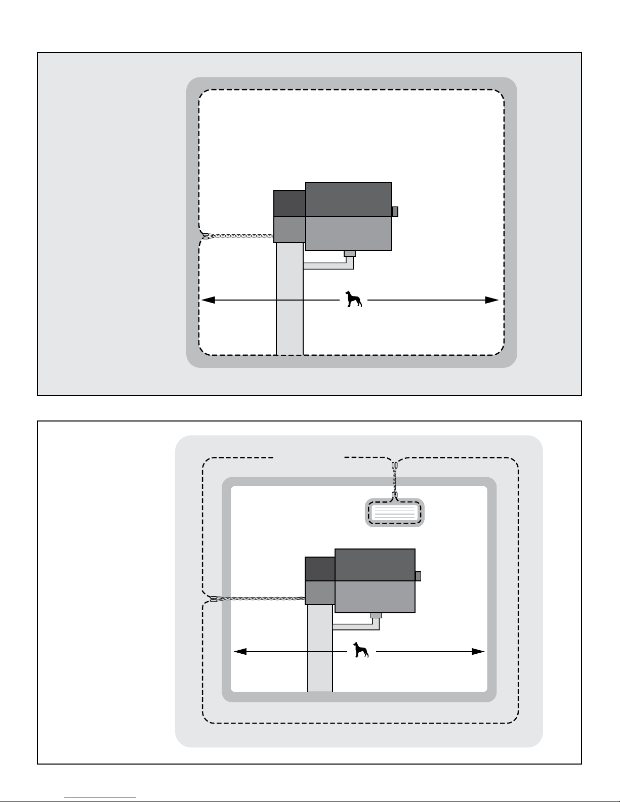
Static Correction Zone
(Infinite Containment Area)
YardMax® Mode (A)
Boundary Wire
Pet Area
30% More Yard
Than Traditional Mode
Non-Containment Area
Warning Zone
Traditional Mode (B)
Boundary Wire
Exclusion Area
Pet Area
Warning Zone
Static Correction Zone
Static Correction Zone
(Finite Containment Area)
www.petsafe.net 7
Operating Guide
Step 1: Have Your Utilities Marked
1. Call your utility company to have your utility lines marked. If you
have neighbors using an in-ground pet containment system, you
will want to ask them where the boundary is located. Trust us, you
really do not want to skip this step.
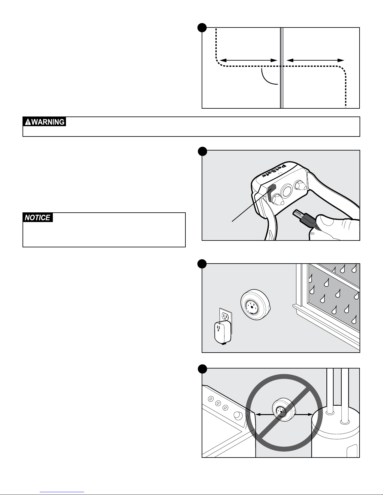
2. Make a plan for how you will work around any large metal
objects (like sheds) or wires. You can cross utility lines but only at
90° angles (1A).
Note: Large metal objects and wires can amplify and/or modulate
radio signals in unpredictable ways.
Underground cables can carry high voltage. Have all underground cables marked before you dig to bury your wire. In
most areas, this is a free service. Avoid these cables when you dig.
1A
Buried Cable
10’
90°
10’
Boundary Wire
Step 2: Charge the Receiver Collar
The receiver charger has two jacks that allow you to charge two
receiver collars at the same time. Open the rubber cap on the back
of the receiver collar (2A). Plug one end of the charger into the outlet
and the other into the receiver collar. The collar light is red while
charging and green when fully charged. The first charge will take
about 2 or 3 hours. Each charge can last up to 3 months depending
on the frequency of use.
Do not charge your receiver collar every night.
Frequent charging can have a negative effect
on the battery. We recommend that the receiver
collar be used until the indicator light blinks red.
Step 3: Install the Surge Protector
and Transmitter
Lightning strikes that occur even several miles away from your
installation can create power surges or spikes which may damage
an unprotected system. The surge protector is included to safeguard
your YardMax® system against surges or spikes that can reach it via
your AC power connection and/or boundary wire.
1. Find a place to install the surge protector and transmitter. There
are a few things to consider when choosing an outlet for your
surge protector and transmitter:
2A
3A
Receiver
Charge Jack
5
4
6
3
7
A
2
B
8
1
9
1
0
• We recommend using an outlet at least 30 ft. from the
breaker box.
• Both the surge protector and transmitter should be indoors, in a
dry, ventilated and protected area.
• You will need to run wire from the transmitter to the boundary
wire, so it must be near window or a wall that you can drill
through (3A). The wire should not be pinched or cross any
utility lines.
• The temperatures in that location should not fall below -10°F
or -23°C.
• Both the surge protector and transmitter should be at least 3 ft.
from large metal objects or appliances (3B). These items may
interfere with the signal consistency.
• In case your system sounds an alarm, place it where you will be
able to hear and access it.
3B
3 ft.
7
B
8
9
10
3 ft.
1-800-732-26778
2. Once you have chosen an outlet and before plugging anything
in, go to your breaker box and turn the power off to that outlet.
3. Then, back at the outlet, remove the center screw that holds the
outlet cover in place.
4. Plug the surge protector into the lower outlet.
5. Using the large screw provided, secure the surge protector to
the outlet.
6. At the breaker box, turn the power back on to the outlet.
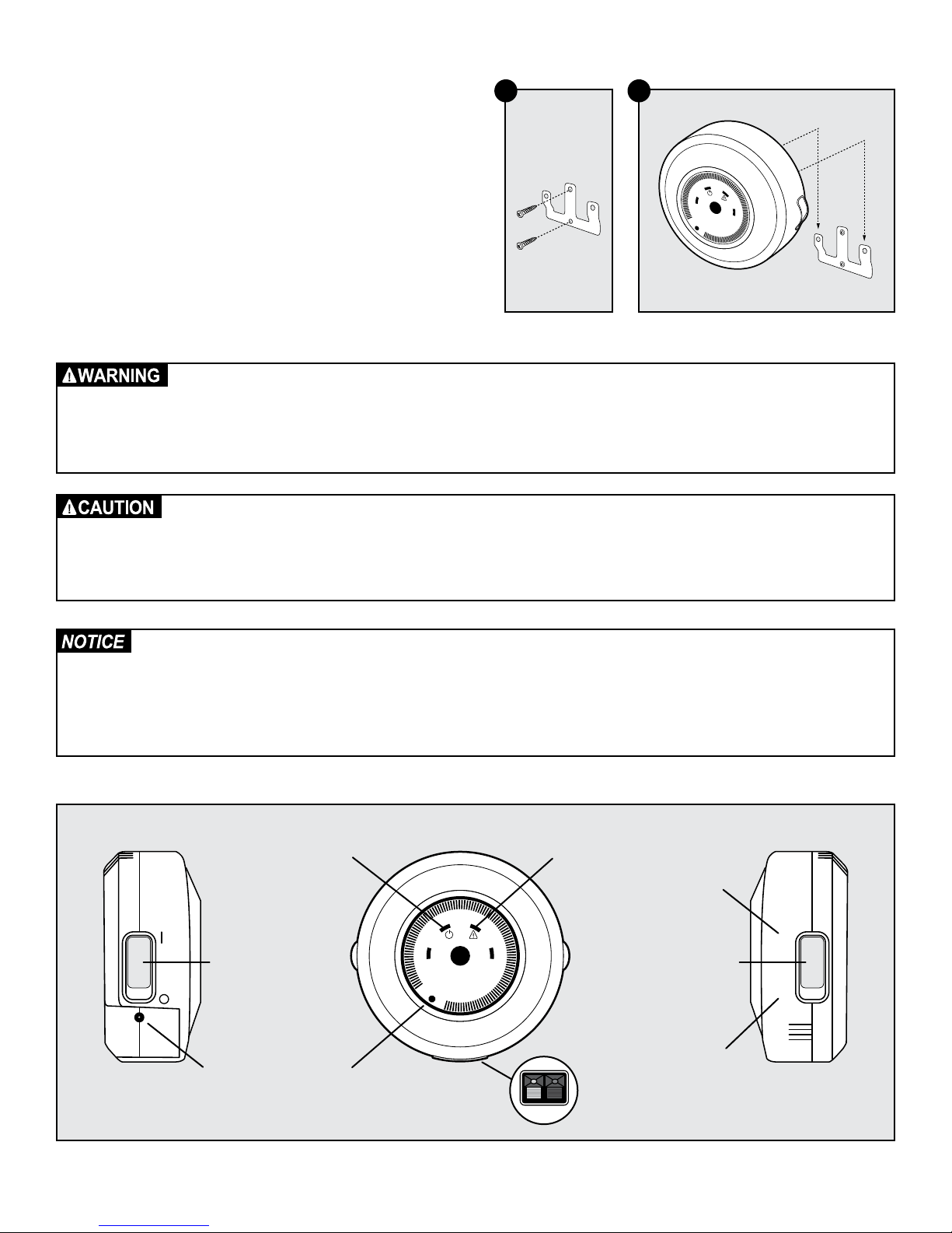
7. Next, you will mount the transmitter somewhere within 5 ft. of the
surge protector. Remove the mounting bracket from the back of
the fence transmitter.
8. Fasten the mounting bracket to the wall using the 2 screws and
anchors provided (3C).
9. Slide the transmitter over the mounting bracket (3D).
• Do not install, connect or remove your system during a lightning storm. If the storm is close enough for you to hear
thunder, it is close enough to create hazardous surges.
• Risk of electric shock. Use the fence transmitter and surge protector indoors in dry location only.
• Turn off power to the outlet before you install or remove your surge protector.
• Risk of electric shock or fire. Use surge protector only with a duplex outlet with center screw.
• Do not install the surge protector if there is not at least 30 ft. (10 m) or more of wire between the electrical outlet
and electrical service panel.
• If possible, DO NOT use an AC circuit protected with a GFCI (ground fault circuit interrupter). Both the surge
protector and the fence system will function. However, in rare cases, nearby lightning may cause the GFCI to trip.
Without power, your pet may escape. You will have to reset the GFCI to restore power to the system.
3C 3D
Mounting
Bracket
4
3
A B
2
1
5
6
7
8
9
10
• Plug the surge protector into a grounded (3-prong) outlet within 5 ft. of the fence transmitter. ALWAYS use a
grounded (3-prong) outlet to ensure protection.
• Do not remove the ground prong from the surge protector plug. Do not use a 3-prong plug to 2-prong outlet
converter. Doing so will make the surge protector ineffective against surges or spikes.
• For added protection, when unused for long periods of time or prior to thunderstorms, unplug from the wall outlet
and disconnect the loop boundary wires. This will prevent damage to the transmitter due to surges.
Power
Indicator Light
Wire Break
Warning Light
YardMax
Mode
®
(Mode A)
5
6
Power
Switch
4
3
A B
2
1
7
8
9
10
Mode
Selection
Switch
A
B
Traditional
Power
Jack
Boundary
Width Dial
Loop Wire
Terminals
Red Black
Mode
(Mode B)
www.petsafe.net 9
Step 4: Design Your Boundary Zone
Basic Planning Tips
• Always design your layout, position the boundary wire and test
the system as outlined in this guide before burying the boundary
wire. You do not want to find out after burying the wire that there
is a problem with your layout or a loose connection somewhere.
• The boundary wire must start at the fence transmitter and make a
continuous loop back to it (4A).
• Always use gradual turns at the corners with a minimum 3 ft.
radius to produce a more consistent boundary (4B).
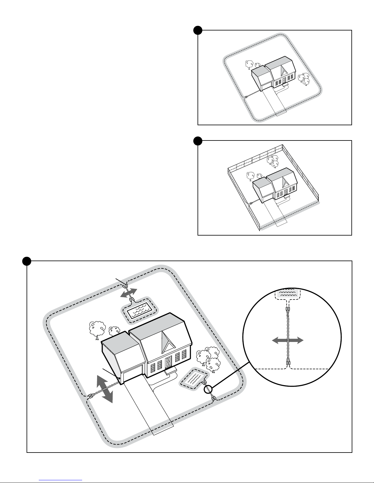
• Create areas in your yard that allow your pet to safely cross
over the boundary wire without static correction by twisting
the boundary wires together 10 to 12 times per foot (4G). This
transmission cancels the signal and allows your pet to safely cross
over that area. This will be explained in more detail in Step 5.
• Yard Max
neighboring YardMax systems.
• Cross any utility lines at a 90° angle.
• Work carefully; a nick in the wire insulation could render it
useless, or create a weak area in the signal field.
• Ensure there is at least 10 ft. between the boundary wire and any
danger zones like roadways.
®
mode layouts need to be at least 10 ft. from
4A
4B
Single or Double Loop Layout
The containment area can be created by using a single boundary
wire that is placed around the entire property (4C) or by doubling
the boundary wire along the same path (4D).
Single Loop Boundary (4C)
• To create a containment area for the entire property
• Used with YardMax mode (A) or Traditional mode (B)
• For exclusion areas around gardens, landscaping or pools
(Traditional mode only)
With a single loop layout, the boundary wire starts at the fence
transmitter, advances out to the yard, continues all the way around
the perimeter of the property and connects back to the fence
transmitter. This forms a boundary zone with a single wire.
Double Loop Boundary (4D)
• To section off only one boundary area or one section of your
yard (e.g., front yard only, or waterfront property)
• Used with Traditional mode (B) only
• The 2 parallel sections of the double boundary wire must be
separated by a minimum of approximately 5 ft. from each
other in order to avoid canceling out the signal as well as provide
an adequate boundary width (4D)
• A double loop layout requires twice as much wire as a single
loop layout because it doubles back along the same path
With a double loop layout, the boundary wire starts at the fence
transmitter, advances out to the yard and continues to form a
boundary zone in one section of your property (e.g., front yard
only). Then the wire makes a U-turn back along the same path and
connects back to the fence transmitter. This forms a boundary zone
with a double wire.
4C
Single Loop
Double Loop
4D
5’
1-800-732-267710
YardMax® Mode (A) Layouts
The YardMax Fence system can only be used with a single
loop layout.
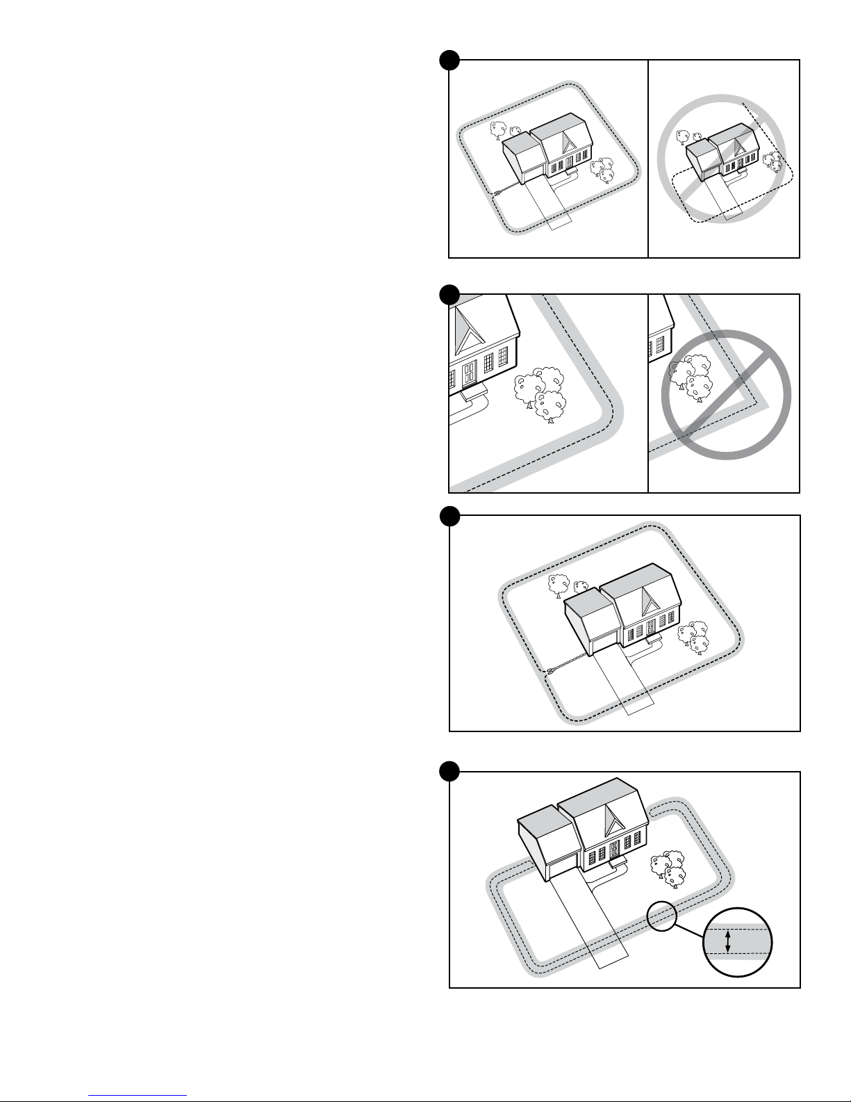
Sample 1(4E): Full Perimeter Loop
With a full perimeter loop, YardMax mode allows your pet to
maximize the pet area and roam the entire property freely and safely.
4E
Sample 1
C
B
Sample 2 (4F): Full Perimeter Loop Using Existing Fence
This layout allows you to include your existing fence as part of your
layout and keep your pet from jumping out or digging under your
existing fence. This layout also greatly reduces the installation time
since most of the wire will not need to be buried.
Using either sample 1 or 2, run the wire from the fence transmitter
to point A, then to point B and so on (B to C to D to E) all the way
around the entire property until back to point A again. The wires from
point A will then need to be twisted and connected back to the fence
transmitter inside your home.
Traditional Mode Layouts (Setting B)
Traditional mode can be used with either a single loop or a double
loop layout. Sample 1 (4E) and Sample 2 (4F) layouts may be also
be used in Traditional mode.
Sample 3 (4G): Perimeter Loop with Exclusion Areas
(Single Loop)
This layout allows you to keep your pet out of gardens, pools or
landscaping within your yard.
4G
D
A
E
Sample 2
4F
C
B
D
A
E
Sample 3
Splices
Place
Transmitter
Inside
Wire
10 Twists/ft.
Pets Can
Safely Cross
Twisted Wires
Pets Can
Safely Cross
Twisted Wires
www.petsafe.net 11
 Loading...