

Page 1
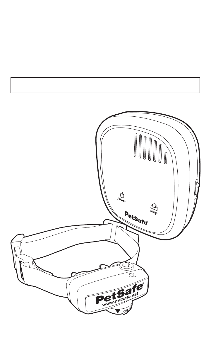
PetSafe® Deluxe
Little Dog
In-Ground Fence
™
Operating and Training Guide
Please read this entire guide before beginning.
Model Number
PIG00-10773
Page 2

Important Safety Information
Explanation of Attention Words and Symbols used in this guide
This is the safety alert symbol. It is used to alert you to potential personal injury
hazards. Obey all safety messages that follow this symbol to avoid possible
injury or death.
WARNING
CAUTION
CAUTION
NOTICE
WARNING
CAUTION
WARNING indicates a hazardous situation which, if not avoided,
could result in death or serious injury.
CAUTION, used with the safety alert symbol, indicates a
hazardous situation which, if not avoided, could result in minor or
moderate injury.
CAUTION, used without the safety alert symbol, indicates a
hazardous situation which, if not avoided, could result in harm to
your pet.
NOTICE is used to address safe use practices not related to
personal injury.
Not for use with aggressive dogs. Do not use this product if your •
dog is prone to aggressive behavior. Aggressive dogs can cause
severe injury or death to their owners and others. If you are not
sure that this product is right for your dog, please talk to your
veterinarian or a certifi ed trainer.
Underground cables can carry high voltage. Have all underground •
cables marked before you dig to bury your wire. In most areas this
is a free service. Avoid these cables when you dig.
Follow all safety instructions for your power tools. Be sure to always •
wear your safety goggles.
Do not install, connect, or remove your system during a lightning •
storm. If the storm is close enough for you to hear thunder, it is
close enough to create hazardous surges.
Risk of electric shock. Use the Fence Transmitter and Surge •
Protector indoors in dry location only.
Turn off power to outlet before you install or remove your•
Surge Protector.
Risk of electrical shock or fi re. Use Surge Protector only•
with a duplex outlet with center screw. Attach unit with long
screw supplied.
Risk of injury. Wire on top of the ground may be a trip hazard;•
Use care in how you place your wires.
Do not install the Surge Protector if there is not at least 30 feet•
(10 meters) or more of wire between the electrical outlet and
electrical service panel.
2 Customer Care Center 1-800-732-2677
Page 3

CAUTION
This PetSafe® In-Ground Fence™ is not a solid barrier. This system is
designed to act as a deterrent to remind pets by Static Correction to
remain in the boundary established. It is important that you reinforce
training with your pet on a regular basis.
Proper fi t of the collar is important. A collar worn for too long or made
too tight on the pet’s neck may cause skin damage. Ranging from
redness to pressure ulcers; this condition is commonly known as
bed sores.
- Avoid leaving the collar on the dog for more than 12 hours
per day.
- When possible reposition the collar on the pet’s neck every
1 to 2 hours.
- Check the fi t to prevent excessive pressure; follow the
instructions in this manual.
- Never connect a lead to the electronic collar; it will cause
excessive pressure on the contacts.
- When using a separate collar for a lead, don’t put pressure
on the electronic collar.
- Wash the dog’s neck area and the contacts of the collar
weekly with a damp cloth.
- Examine the contact area daily for signs of a rash or a sore.
- If a rash or sore is found, discontinue use of the collar until
the skin has healed.
- If the condition persists beyond 48 hours, see your
veterinarian.
- For additional information on bed sores and pressure
necrosis, please visit our website.
These steps will help keep your pet safe and comfortable. Millions of
pets are comfortable while they wear stainless steel contacts. Some
pets are sensitive to contact pressure. You may fi nd after some time
that your pet is very tolerant of the collar. If so, you may relax some
of these precautions. It is important to continue daily checks of the
contact area. If redness or sores are found, discontinue use until the
skin has fully healed.
You may need to trim the hair in the area of the Contact Points. Never
shave the dog’s neck; this may lead to a rash or infection.
The receiver collar should not be on your dog when the system •
is tested. Your pet may receive an unintended correction.
The Boundary Width of the system must be tested whenever •
an adjustment is made to the containment fi eld to prevent
unintended corrections to your pet.
If you use a collar and leash for training, be sure the extra collar •
does not put pressure on the contact points.
Always remove your dog’s receiver collar before performing any •
transmitter testing.
If possible, DO NOT use an AC circuit protected with a Ground •
Fault Circuit Interrupter (GFCI) or Residual Current Device (RCD).
In rare cases, nearby lightning strikes may cause the GFCI or RCD
to trip. Without power your dog may be vulnerable to escape. You
will have to reset the GFCI or RCD to restore power to the system.
www.petsafe.net 3
Page 4

NOTICE
Plug the Surge Protector into a grounded (3-prong) outlet that is •
within 5 feet of the Fence Transmitter. ALWAYS use a grounded
(3-prong) outlet to ensure maximum protection.
Do not remove the ground prong from the Surge Protector•
plug. Do not use a 3-prong plug to 2-prong outlet converter.
Doing so will make the Surge Protector ineffective against
surges or spikes.
Use care when mowing or trimming your grass not to cut the •
loop wire.
Verify that the boundary loop and transmitter wires connect to •
the proper Surge Protector terminals. Reversed connections will
result in an increased risk of surge related damage.
For added protection, when unused for long periods of time •
or prior to thunderstorms, unplug from the wall outlet and
disconnect the loop boundary wires. This will prevent damage to
the transmitter due to surges.
To prevent an unintended correction, after the Boundary •
Flags have been placed, be sure to set the static correction
on the receiver collar back to level 1 tone only.
4 Customer Care Center 1-800-732-2677
Page 5

Thank you for choosing PetSafe® brand. You and your pet deserve
a companionship that includes memorable moments and a shared
understanding together. Our products and training tools promote a lifestyle
of protection, teaching, and lo v e — essentials tha t infl uence memories for a
lifetime. If you ha v e an y questions about our products or training y our pet,
please visit our website at www.petsafe.net or contact our Customer Care
Center at 1-800-732-2677.
To get the most protection out of your warranty , please register your product
within 30 days at www.petsafe.net. By registering and keeping your receipt,
you will enjoy the product’ s full w arranty and should you ev er need to call the
Customer Care Center, we will be able to help y ou faster. Most importantly,
PetSafe® will never give or sell your valuable information to anyone. Complete
warranty information is available online at www.petsafe.net.
Table of Contents
Components ........................................................................................7
Other Items You May Need ...................................................................7
How the System Works .........................................................................8
Key Defi nitions ....................................................................................8
Operating Guide ................................................................................9
Locate the Fence Transmitter .............................................................9
Lay Out the System ...........................................................................9
Sample Layouts ...............................................................................10
Position the Boundary Wire .............................................................12
Connect the Wires to the Surge Protector and Fence Transmitter
(USA and Canada) .........................................................................14
Connect the Wires to the Fence Transmitter
(Australia & New Zealand) ..............................................................16
Transmitter Set-up ..........................................................................16
Prepare the Receiver Collar .............................................................17
Function and Response Table ..........................................................18
Set the Boundary Width and Test the Receiver Collar ........................19
Install the Boundary Wire ................................................................21
Place the Boundary Flags ................................................................22
Fit the Receiver Collar .....................................................................23
Training Guide ................................................................................25
Be Patient With Your Pet ..................................................................25
Day 1 - Boundary Awareness ...........................................................25
Days 2 thru 4 - Continue Boundary Awareness ................................26
Days 5 thru 8 - Distraction Phase ....................................................27
Days 9 thru 14 - Unleashed Supervision ..........................................28
Days 15 thru 30 - Pet Monitoring ....................................................28
Taking Your Pet Out of the Pet Area .................................................28
Accessories ........................................................................................29
www.petsafe.net 5
Page 6

Troubleshooting ...............................................................................30
Additional Information .......................................................................31
System T est ........................................................................................32
Transmitter Loop Test (USA and Canada) ..........................................33
Transmitter Loop Test (Australia and New Zealand) ............................33
Wire Break Location Test ....................................................................34
Terms of Use and Limitation of Liability .............................................34
Compliance .......................................................................................35
Customer Care International ..............................................................35
Perchlorate Battery .............................................................................35
Mounting T emplate ............................................................................36
Layout Grid .......................................................................................36
6 Customer Care Center 1-800-732-2677
Page 7
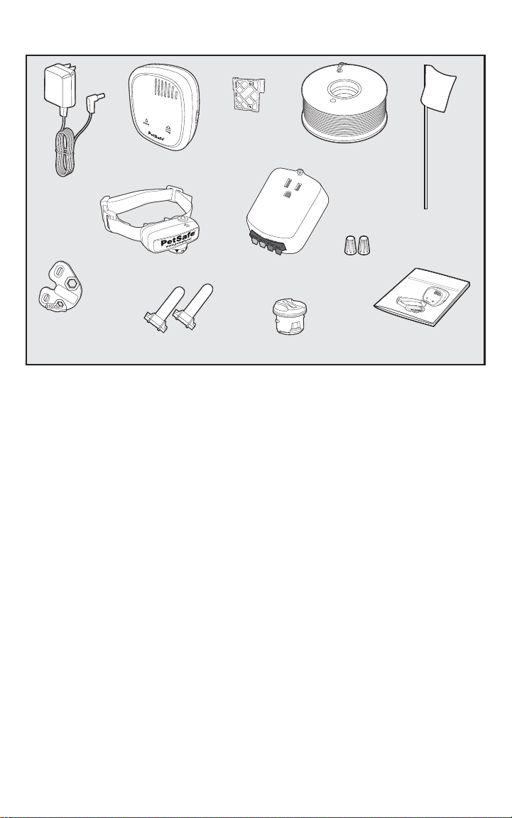
Components
Fence
Transmitter
Power
Adapter
Mounting
Bracket
Boundary Wire - 500 ft.
Boundary Flags - 50
Test Light
Tool
Receiver Collar
Gel-filled
Capsules
Surge Protector
(USA and Canada only)
Battery
®
(PetSafe
RFA-188)
Wire Nuts
Mo
d
e
PI
G
0
Operating and
Training Guide
Other Items You May Need
Additional wire and fl ags•
(Part #PRFA-500)
Tape measure•
Small Phillips screwdriver•
Drill & mounting hardware•
Shovel or lawn edger•
Pliers•
Wire stripping pliers•
Scissors•
Lighter•
Fence installation and training help, interactive fence planning software:
www.petsafe.net/fence
Additional wire nuts•
Ground rod and clamp•
Waterproofi ng compound (e.g. silicone caulk)•
PVC pipe or water hose•
Circular saw with masonry blade•
Staple gun•
Non-metallic collar and leash•
L
i
P
ttl
etSa
e
D
fe
og I
®
O
p
D
e
n
r
a
e
-Gr
tin
luxe
P
g
le
oun
a
a
se
nd Tr
r
e
a
d
d
t
h
is
a
F
e
i
n
n
e
t
i
i
r
nc
n
e
g
g
u
™
Gu
i
e
d
e
b
e
i
fo
d
r
e
e
b
e
g
l
i
N
n
n
u
i
m
n
g
0
b
.
e
1
r
0
7
7
3
www.petsafe.net 7
Page 8
How the System Works
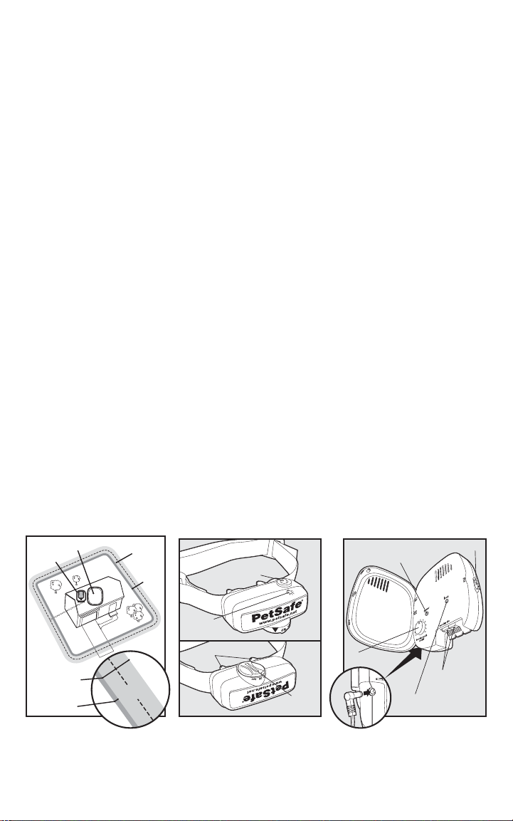
A radio signal travels from the Fence Transmitter through a buried wire, marking the boundaries you
wish to set for your dog. Your dog w ears a Receiver Collar that detects the signal a t the boundary .
As your dog approaches the boundary, the receiv er issues a warning tone. If he proceeds further, he
receives a safe but startling Static Correction. While harmless, the correction will persuade him to
stay in the containment area you’ve established. Boundary fl ags are a temporary visual aid for your
pet; remove them after training. This PetSafe® Deluxe Little Dog In-Ground Fence™ has been proven
safe, comfortable, and effective for pets ov er 6 pounds, neck sizes 6 to 16 inches.
Key Definitions
Fence T ransmitter: Transmits the radio signal through the Boundary Wire.
Pet Area: Area within the Warning Zone where your pet can roam freely.
Warning Zone: Outer edge of the Pet Area where your pet’ s Receiv er Collar begins to beep,
warning him not to go into the Static Correction Zone.
Static Correction Zone: Zone beyond the W arning Zone where your pet’s Receiver Collar will
emit a Static Correction, signaling him to return to the Pet Area.
Boundary Width: Combination of the Warning Zone and the Static Correction Zone.
Surge Protector: Installed with the Fence Transmitter to protect it from lightning strikes and
power surges. (USA and Canada only)
Receiver Collar: Receives the radio signal from the Boundary Wire.
Correction Level Button: Adjusts the level of Static Correction your pet receives in the Sta tic
Correction Zone.
Receiver Indicator Light: Indicates the level of correction at which the Receiver Collar is set.
This light also serves as a low battery indicator.
Contact Points: Delivers the safe Static Correction when your pet moves into the Sta tic
Correction Zone.
Power J ack: Where the Power Adapter plugs into the F ence Transmitter.
Boundary Control Switch: Switch located on the Fence Transmitter to adjust according to
the length of Boundary Wire used.
Boundary Wire T erminals: Where the Boundary Wires connect to the Fence T ransmitter in
order to complete a continuous loop.
Loop Indicator Light: Indicates that the Boundary Wire makes a complete loop, enabling the
signal to be transmitted.
Boundary Width Control: Adjusts the width of the Warning and Static Correction Zones.
Note: Adjusting the knob does not change the level of Static Correction on the Receiver Collar.
Surge
Protector
with Power
Adapter
Fence
Transmitter
Static Correction
Pet
Area
Zone
Receiver Collar Fence Transmitter
(Top)
Power Light
Warning
Zone
Correction
Level Button
Boundary Control Switch
Receiver
Indicator
Light
Contact Points
Static Correction
Zone
Warning
Zone
Boundary
Width
W ant professional installa tion help? Invisible Fence
(Bottom)
Battery
Module
®
Brand installers will come to your home
Boundary Width
Control
Power
Jack
Boundary Wire
Terminals
Loop Indicator Light
and install your new PetSafe® System for an additional cost. Contact your local dealer at
1-877-866-DOGS (3647) or visit our website at www.invisiblefence.com for more information.
8 Customer Care Center 1-800-732-2677
Page 9
Operating Guide
10
Twists/ft.
Step
1
Step
2
Locate the Fence Transmitter
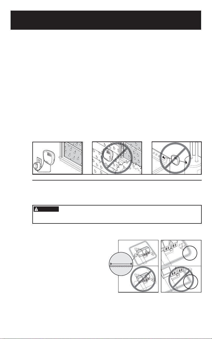
Place the Fence Transmitter:
In a dry, well v entilated, protected area (• 1A, 1B).
In an area where temperatures do not fall below freezing (e.g., garage, basement,•
shed, closet).
Secured to a stationary surface using the mounting hardware. A mounting template is •
included on the back of this guide
At least 3 feet from large metal objects or appliances as these items may interfere with •
the signal consistency (1C).
To mount the Fence Transmitter, screw the mounting bracket onto a stationary
surface such as a wall, and slide the Fence Transmitter onto the bracket. Once
you have mounted the Fence Transmitter, the Boundary Wire must exit the
building. This can be accomplished via a window or through a hole drilled through
the wall. Ensure the drill path is clear of any utilities. Make sure the Boundary
Wire is not cut off or pinched by a window, door, or garage door, as this can
damage it over time.
To prevent fi res and electrical hazards, install the Fence Transmitter in buildings
that are in accordance with state and local electrical codes.
1A
1B
1C
3ft.
Lay Out the System
Basic Planning Tips
WARNING
For information regarding how these underground wires can affect your
system’s opera tion, see Step 3 Position the Boundary Wire.
The Boundary Wire • MUST start at
the Fence T ransmitter and make a
continuous loop back (2A).
T wisting the Boundary Wire cancels •
the signal and allows your pet to cross
over that area without correction.
Plastic or metal piping will not cancel
the signal. Twist the Boundary Wire
10 to 12 times per foot to cancel the
signal (2A).
Underground cables can carry high voltage. Have all underground
cables marked before you dig to bury your wire. In most areas this
is a free service. Avoid these cables when you dig.
2A 2B
www.petsafe.net 9
Page 10
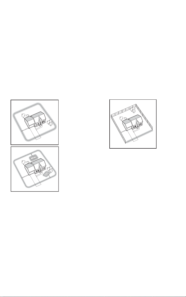
Design a layout that is suitable for your yard. Sample la y outs are provided in this section, •
and a grid for designing your layout is provided in the back of this guide.
Fence planning software is available online at www.petsafe.net/fence.•
Always use gradual turns at the corners with a minimum of 3 foot radius to produce•
a more consistent boundary (2B). Do not use sharp turns, as this will cause gaps in
your boundary.
To properly contain your pet, we recommend setting a Boundary Width for the •
Warning and Static Correction Zones to approximately 12-20 feet (6 to 10 feet on each
side of the wire).
Avoid making passageways too narrow for your pet to mo ve about freely (e.g., along the •
sides of a house).
The Receiver Collar can be activated inside the house if the Boundary Wire runs along •
the outside wall of the house. If this occurs, remo v e y our pet’s Receiver Collar before
bringing him inside, decrease the range using the Boundary Width Control knob or
consider an alternative layout.
Sample Layouts
2C
2D
Sample 1:
Perimeter Loop
(Single Loop) The
Perimeter Loop is
the most common
layout. This will
allow your pet to
freely and safely
roam your entire
property (2C). It
can also protect
gardens, pools and
landscaping (2D).
2E
B
A
C
D
E
Sample 2 (2E): Perimeter Loop
Using Existing Fence (Single
Loop) This layout allows you to
include your existing fence as part of
your layout and keep your pet from
jumping out or digging under your
existing fence. It reduces the amount
of wire which will need to be buried.
From the Fence Transmitter, run the
wire to A, A to B, B to C, C to D,
D to E, E to A, twist the wires from
A back to the Fence Transmitter.
See the “Install the Boundary Wire”
section for more information on
attaching the wire to a fence.
10 Customer Care Center 1-800-732-2677
Page 11
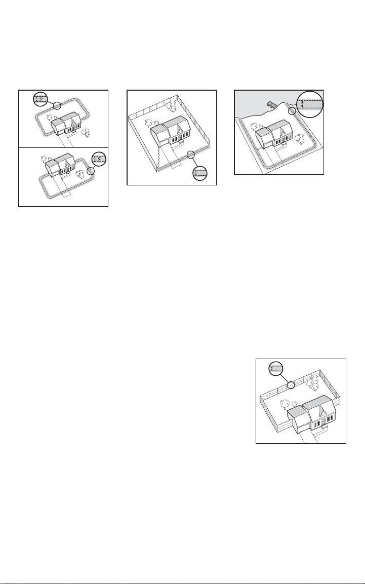
Double Loop
5'
5'
5'
A Double Loop must be used when you are not establishing the Boundary Zone on all sides of
your property.
When using a Double Loop, the Boundary Wire must be separated by a minimum of
5 FEET to avoid canceling the signal. Remember that a Double Loop will require twice as
much wire.
2F
C
B
A
B
C
Sample 3 (2F): Front or
Back Y ard Only
(Double Loop) From the
Fence T ransmitter, run
the wire to A, A to B, B
to C, C to D, D to E, E
to F, make a U-turn and
follow your path all the
way back to A, keeping
the wire separated at least
5 feet. Twist the wire from
A back to the Fence
Transmitter.
D
E
F
A
E
F
D
2G
B
A
Sample 4 (2G): Front
Boundary Only
(Double Loop) From the
Fence T ransmitter, run
the wire to A, A to B, B
back to A keeping the
wire separated at least 5
feet. Twist the wire from
A back to the Fence
Transmitter.
2H
E
B
A
C
D
Sample 5 (2H): Lake
Access (Double Loop)
From the Fence
Transmitter, run the wire
to A, A to B, make a
U-turn and go to C, C to
D, D to E, make a U-turn
and follow your path all the
way back to A keeping wire
separated at least 5 feet.
Twist the wire from A back
to the Fence Transmitter.
Sample 6 (2J): Wire Loop Attached to Existing Fence
(Double Loop) This layout allows you to include your existing
2J
D
fence as part of your layout and keep your pet from jumping out
or digging under your existing fence. It reduces the amount of
wire which will need to be buried. Run the wire from the Fence
Transmitter to A, A to B, B to C, C to D, D to E, E to F, make
C
E
F
a U-turn and follow your path all the way back to A, keeping the
wire separated at least 5 feet. Twist the wire from A back to the
Fence T ransmitter. See the “Install the Boundary Wire” section
A
B
for more information on attaching the wire to a fence.
www.petsafe.net 11
Page 12
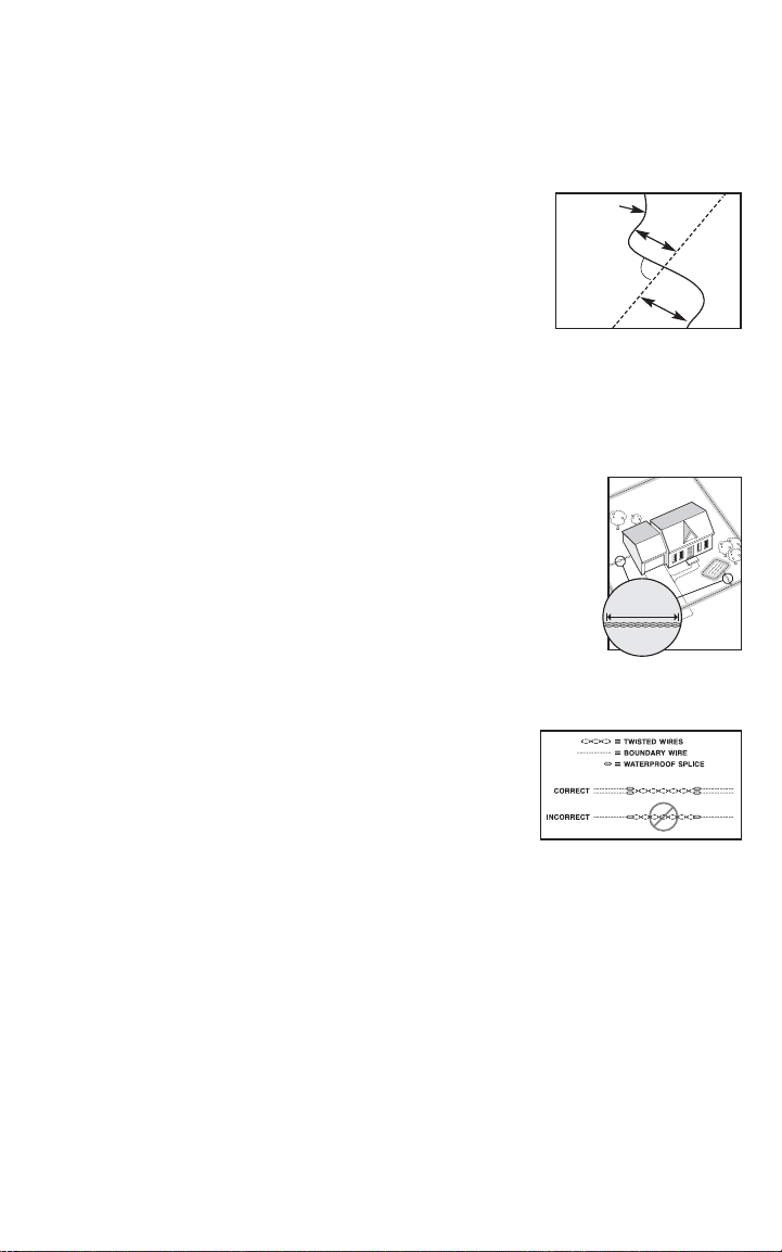
10
Twists/ft.
Step
3
Position the Boundary Wire
Lay out the Boundary Wire using your planned boundary and test the
system BEFORE burying the wire or attaching it to an existing fence.
This will make any layout changes easier. Work carefully. A nick in the
wire insulation can diminish the signal strength and create a weak area
where your pet can escape.
Running the Boundary Wire parallel to and within
10 feet of electrical wires, neighboring containment
systems, telephone wires, television or antenna cables,
or satellite dishes may cause an inconsistent signal. If
you must cross any of these, do so a t 90-degree angles
(perpendicularly) (3A).
If separating the wire by at least 10 feet from a
neighboring containment system’s wire does not reduce
the inconsistent signal, contact the Customer Care Center.
Twisting and Connecting the
Boundary Wire
T wisting the Boundary Wire cancels the signal and allows your pet
to cross over that area safely (3B). The signal cannot be cancelled
by running the wire through plastic or metal piping. Using shielded
cable in place of the Boundary Wire will also not cancel the signal.
Refer to fi gure (3C) for the correct method of twisting the wire. You
can twist your own wire by cutting two equal lengths of Boundary
Wire supplied and twisting them together. Anchor one end of the
wires to something secure and insert the other end in a power drill.
Pull the wire taut. The drill enables you to twist the wire quickly.
T wist the Boundary Wire 10 to 12 times per foot to cancel the
signal. Once you hav e completed y our boundary layout connect
one end of the twisted wire to the Perimeter Loop and see Step 4 to
connect the other end of the twisted wire to the Surge Protector.
If your layout includes a Secondary Loop to protect
landscaping, pool or garden areas, connect the twisted wire
between the Perimeter Loop and the Secondary Loop.
Boundary Wire
3A
3C
10’
90˚
10’
3B
Buried Cable
12 Customer Care Center 1-800-732-2677
Page 13
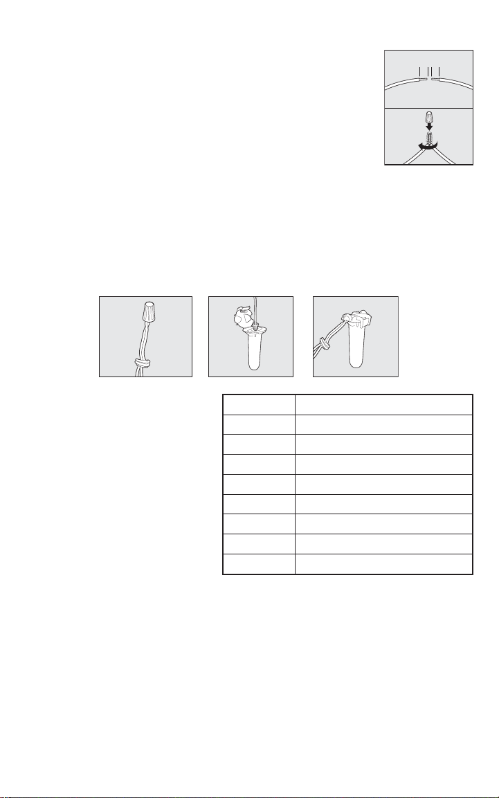
To Splice or Repair the Boundary Wire
If you need additional Boundary Wire to expand your wire loop, you
will need to splice the wires together. Note the locations of all splices for
future reference.
Strip approximately 3⁄8 inch of insulation off the ends of the Boundary
Wires to be spliced (3D). Make sure the copper Boundary Wire is not
corroded. If the Boundary Wire is corroded, cut it back to expose clean
copper wire.
Insert the stripped ends into the wire nut and twist the wire nut around
the wires. Ensure that there is no copper exposed bey ond the end of the
wire nut. Tie a knot 3 to 4 inches from the wire nut (3E). Ensure that the
wire nut is secure on the wire splice.
Once you have securely spliced the wires together, open the lid of the gel-fi lled splice capsule
and insert the wire nut as deeply as possible into the waterproof gel inside the capsule (3F).
Snap the lid of the capsule shut (3G). For proper system performance, the splice connection
must be waterproof.
If your splice pulls loose, the entire system will fail. Make sure your splice is secure. Additional
gel-fi lled splice capsules and wire nuts are available through the Customer Care Center.
3E
3F
3G
3D
3/8"
3/8"
1
2
Additional
Boundary Wire
Extra direct burial Boundary Wire can
be purchased in 500 foot spools at the
store where you purchased the kit or
through the Customer Care Center at
1-800-732-2677.
Note: When adding Boundary Wire, it must
act as a continuous loop.
The table at right indicates the
approximate length of Boundary Wire
needed for a square, Single Loop layout.
Acres Feet of Wire Needed
1/4 415
1/3 480
1/2 590
1 835
2 1180
5 1870
10 2800
25 4500
Length will vary due to the amount of
twisted wire and layout used.
www.petsafe.net 13
Page 14
Step
Connect the Wires to the Surge
Protector and Fence Transmitter
(USA and Canada)
4
Surge Protection
Lightning strikes that occur even several miles away from your installation can
create power surges or spikes which may damage your unprotected electronic pet
containment system. The Surge Protector included with this system is designed to
protect your In-Ground Fence
power connection and/or your buried Boundary Wire.
™
from surges or spikes that can reach it via your AC
Install the Surge Protector & Connect the
Wires(4A)
WARNING
CAUTION
CAUTION
NOTICE
Do not install, connect, or remove your system during a lightning •
storm. If the storm is close enough for you to hear thunder, it is
close enough to create hazardous surges.
Turn off power to outlet before you install or remove your•
Surge Protector.
Risk of electrical shock or fi re. Use Surge Protector only with a •
duplex outlet with center screw. Attach unit with long screw supplied.
Risk of electric shock. Use the Fence Transmitter and Surge •
Protector indoors in dry location only.
Do not install the Surge Protector if there is not at least 30 feet•
(10 meters) or more of wire between the electrical outlet and
electrical service panel.
If possible, DO NOT use an AC circuit protected with a GFCI •
(ground fault circuit interrupter). In rare cases, nearby lightning
strikes may cause the GFCI to trip. Without power your dog may
be vulnerable to escape. You will have to reset the GFCI to restore
power to the system.
Plug the Surge Protector into a grounded (3-prong) outlet that is •
within 5 feet of the Fence Transmitter. ALWAYS use a grounded
(3-prong) outlet to ensure maximum protection.
Do not remove the ground prong from the Surge Protector plug. •
Do not use a 3-prong plug to 2-prong outlet converter. Doing so
will make the Surge Protector ineffective against surges or spikes.
14 Customer Care Center 1-800-732-2677
Page 15
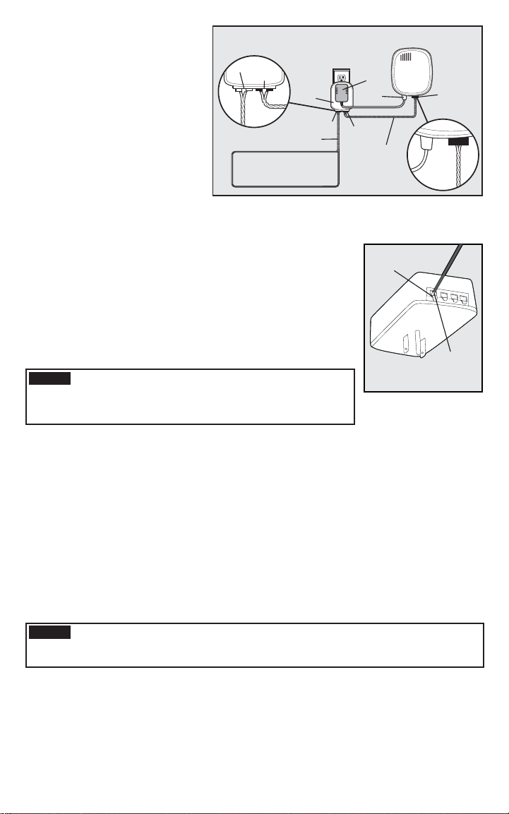
Turn the power OFF to the 1.
outlet that the Surge Protector
and Fence T ransmitter will be
plugged into.
We recommend that, if 2.
possible, use the outlet center
screw that holds the cover
plate in place to secure the
Surge Protector to the outlet.
To do this, tape the top of
the cover plate to the wall,
then remove the cover plate
4A
Loop
Transmitter
LP-4100
Red Loop Tabs
Boundary Wires
(Twisted)
Boundary Wire
Loop
Power
Adapter
Power
Jack
Black
Transmitter
Tabs
Transmitter
Fence Transmitter
Wires
(Twisted)
center screw. Plug the Surge
Protector into the lower outlet
and then secure the cover plate using the longer screw included with the protector. The
screw is for mechanical attachment only and does not ground the protector. Remov e the
tape and turn ON the power to the outlet.
Run the Boundary Wire through a windo w, under a door, 3.
through a crawl space vent, or any other appropriate available
access. You can also drill a hole through your wall.
3
Strip 4.
⁄8 inch of insulation from the ends of the Boundary Wire.
4B
Push T ab
Down
Insert the stripped ends into the 2 left red connector holes on
the bottom of the Surge Protector labeled “Loop” (4B). There
should be 1 wire in each connector hole. Press the plastic tab,
insert the wires and release the tab. Make sure the wires do not
touch each other at the terminals.
NOTICE
Verify that the boundary loop and transmitter wires
connect to the proper Surge Protector terminals.
Reversed connections will result in an increased risk of
surge related damage.
Boundary Wire
Terminals
LOOP TRANSMITTER
Insert bare end
of wire into
opened slot
and release tab
to lock.
Determine the length of wire needed to pass from the Surge Protector to the Fence 5.
Transmitter . Measure and cut 2 lengths of wire, then strip 3⁄8 inch of insulation at both
ends. Twist the 2 lengths together, with at least 10-12 twists per foot, so the wires will not
send out a signal.
Insert the ends of the the twisted transmitter wires into the right 2 black connectors at the 6.
bottom of the Surge Protector labeled “Transmitter”.
Press the red plastic tabs on the Fence T ransmitter and insert the opposite ends of the 7.
twisted wire into the Boundary Wire Terminals.
Turn the Boundary Width Control knob to 10. This will set the Boundary Width at the8.
maximum width.
Plug in the transmitter power adapter to the outlet on the front of the Surge Protector.9.
The Power Light and Loop Indica tor Lights should come on. If this does not happen, see 10.
the “Troubleshooting” section.
NOTICE
For added protection, when unused for long periods of time or prior to
thunderstorms, unplug from the wall outlet and disconnect the loop boundary
wires. This will prevent damage to the transmitter due to surges.
www.petsafe.net 15
Page 16
Connect the Wires to the Fence
Transmitter (Australia & New Zealand)
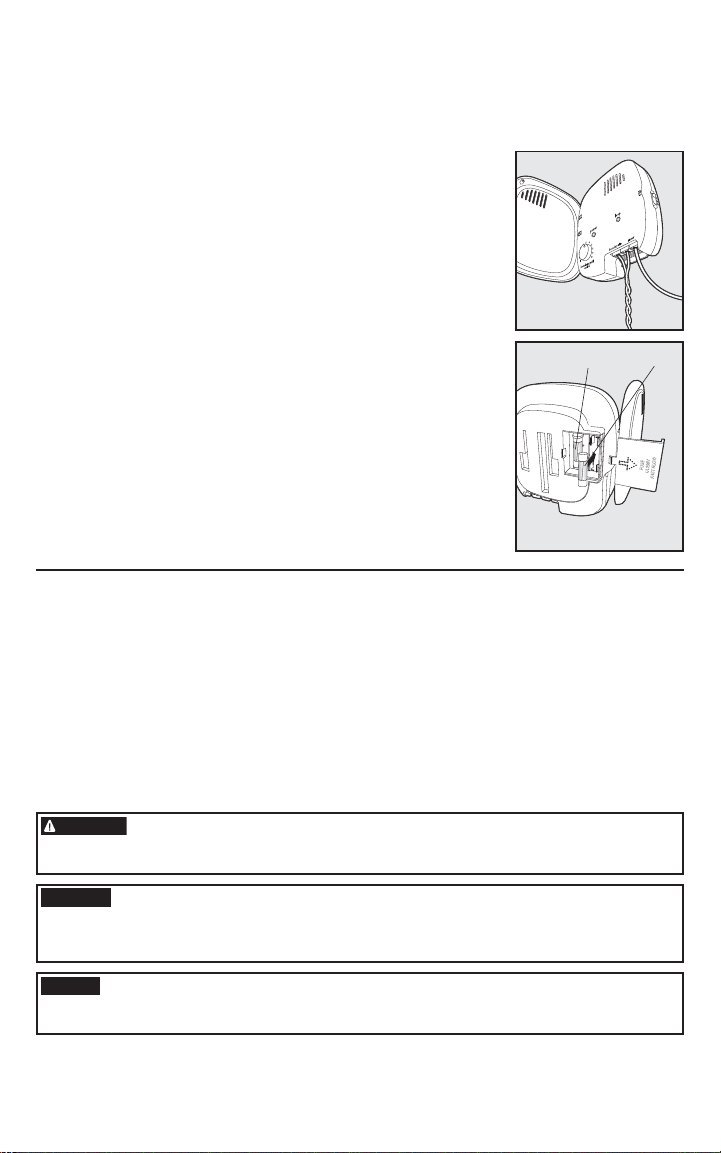
Ground Wire (4C)
Proper grounding, although not necessary for the system to work,
will help reduce the chance of electrical surges causing damage to
your Fence Transmitter and/or Power Adapter . To ground your unit,
you will need a stranded 10 gauge insulated copper wire and a UL
approved grounding clamp to connect the wire to the grounding rod
located at your electrical power service entrance. These items may be
obtained at most local hardware or electrical supply stores. Connect
one end of the Ground Wire to the Ground Terminal located on
the Fence T ransmitter and the other end of the Ground Wire to the
grounding rod located at the electrical power service entrance to
your home. This grounding rod is normally located below the electric
meter mounted on your home. Secure the wire to the grounding rod
using the UL approved grounding clamp.
4C
4D
Fuse Protection (4D)
The Fence T ransmitter is also equipped with a 250 v olt, 1 amp
fuse to protect the unit’s electronic circuitry from electrical power
surges. To locate the fuse, slide off the lid on the back of the Fence
Transmitter . A spare fuse is also provided.
Transmitter Set-up
Run the Boundary Wire through a window, under a door, through a crawl space vent, or 1.
any other appropriate available access. you can also drill a hole through your wall.
3
Strip 2.
⁄8 inch of insulation from the ends of the Boundary Wire.
Press the red tabs on the Fence Transmitter and insert the opposite ends of the twisted 3.
wire into the Boundary Wire Terminals.
Turn the Boundary Width Control Knob to 10. This will set the Boundary Width at the 4.
maximum width.
Plug Power Adapter into Power Jack and AC Power Outlet.5.
The Power Light and Loop Indicator Lights should come on. If this does not happen see 6.
the “Troubleshooting” section.
WARNING
Do not install, connect, or remove your system during a lightning storm. If the storm is •
close enough for you to hear thunder, it is close enough to create hazardous surges.
Risk of electric shock. Use the Fence Transmitter indoors in dry location only.•
Ground
FuseSpare Fuse
Wire
CAUTION
NOTICE
16 Customer Care Center 1-800-732-2677
If possible, DO NOT use an AC circuit protected with a Ground Fault Circuit Interrupter
(GFCI) or Residual Current Device (RCD). In rare cases, nearby lightning strikes may
cause the GFCI or RCD to trip. Without power your dog may be vulnerable to escape.
You will have to reset the GFCI or RCD to restore power to the system.
For added protection, when unused for long periods of time or prior to thunderstorms,
unplug from the wall outlet and disconnect the loop boundary wires. This will prevent
damage to the transmitter due to surges.
Page 17

Step
5
Prepare the Receiver Collar
To Insert and
Remove the Battery
Note: Do not install the battery while the
Receiver Collar is on your pet.
This Receiver Collar utilizes a
replaceable PetSafe
(RFA-188). This unique battery is
designed to make battery replacement
easier and increase water protection.
To activate the collar, insert the battery
module (5A). Using the edge of the
Test Light Tool as shown, turn the
battery clockwise until the vertical line
on the battery is pointed to the “ON”
position (5B). If the PetSafe® Receiver
Collar is not going to be used on
the pet immediately, leave it in the
“OFF” position.
To remove the battery, turn the battery counter-clockwise using the edge of the
Test Light Tool as shown (5C, 5D). DO NOT attempt to cut into or pry open
the battery. Be sure to discard the used battery properly.
A replacement PetSafe® battery can be found at many retailers. Contact the
Customer Care Center or visit our website at www.petsafe.net to locate a retailer
near you.
®
battery
Static Correction and Battery Test Feature
When the RFA-188 Battery Module is fi rst installed in the Receiver, the red LED
will fl ash the current correction level setting (1-5). For the next 30 seconds, the
receiver will monitor the battery status and will either fl ash the green LED once
every 5 seconds to indicate a good battery, or fl ash the red LED once every 5
seconds to indicate a low battery condition.
After the 30 second battery test period, the green LED will cease to fl ash if the
battery is good. If the battery was low during the test period, the red LED will
continue to fl ash at a rate of 1 fl ash every 20 seconds to indicate a low battery
condition. In this situation, battery replacement is recommended.
5A 5B
5C
5D
To Set the Static Correction Level
Read all steps before attempting to set the Static
Correction Level.
With the battery installed, press the Correction Level 1.
Button and release when the Receiver Indicator Light
illuminates red (5E).
The Receiver Indicator Light will emit a number of 2. red
fl ashes representing the Static Correction Level (5F).
Increase the Static Correction Level by pressing and 3.
releasing the Correction Level Button within 5 seconds
of the previous fl ashes.
www.petsafe.net 17
5E
5F
Page 18

The Static Correction Levels increase from 1 to 5. Pushing the Correction Level Button
while the Receiver Collar is on level 5 will cause the Receiver Collar to revert to level 1.
Refer to the Function and Response Table to choose the Static Correction level that best fi ts
your pet.
The Receiver Indicator Light acts as a low battery indicator, fl ashing every 20 seconds when
battery replacement is required.
Anti-Linger Prevention
The Anti-Linger Prevention feature keeps your dog from staying in the Warning Zone for
long periods of time and draining the Receiver Collar battery. Your dog will hear a warning
tone when he reaches the Warning Zone. If your dog does not return to the Pet Area after
two seconds, he will receive a continuous Static Correction until he returns to the Pet Area.
Run Through Prevention
This system includes a unique “run-through” prevention so that your dog cannot escape
the Pet Area without receiving an increased level of Static Correction. The Receiver Collar
automatically increases the Static Correction when your dog continues more than 20% of
the way through the pet fencing Boundary Width. For example, if the signal is detected 10
feet from the wire and your dog enters the Static Correction Zone, this feature is activated
when he is approximately 8 feet from the Boundary Wire. Your dog will then receive a Static
Correction that is at an increased level corresponding to the Static Correction level setting
on the Receiver Collar. The Receiver Collar is equipped to automatically increase the level of
Static Correction the longer your pet remains in the Static Correction Zone if the collar is set
at level 2 or above.
Over Correction Protection
In the unlikely event that your pet “freezes” in the Static Correction Zone, this feature
limits the static correction duration to a maximum of 30 seconds. While the system locks
out further static correction, the warning tone will continue until the pet leaves the Static
Correction Zone.
Function and Response Table
Indicator Light
Response
1 Red Flash 1 No Static Correction,
2 Red Flashes 2 Low Static Correction Timid
3 Red Flashes 3 Medium Static Correction Timid or Av erage
4 Red Flashes 4 Medium High Static
5 Red Flashes 5 High Static Correction High Energy
Flashes 1 Red fl ash
every 20 seconds
18 Customer Care Center 1-800-732-2677
Static Correction
Level
Low Battery
Receiver Collar
Function
Tone Only
Correction
Temperament
of Pet
Initial Training Mode
Average or
High Energy
Page 19
Step
6
Set the Boundary Width and Test the
Receiver Collar
With the Boundary Wire in place and properly connected, it
is time to set the containment fi eld and test the system.
CAUTION
Note: The Receiv er Collar is waterproof, which can make the tone
hard to hear.
The fl ashing Test Light when held to the Contact Points
indicates the Receiver Collar is delivering Static Correction.
To best utilize the automatic Run-Through Prevention
feature, the containment Boundary Width should extend
at least 6 to 10 feet on each side of the Boundary Wire (total Boundary Width of
12 to 20 feet).
Apply Power to the Fence Transmitter 1.
with the supplied Power Adapter.
Set the Boundary Width Control 2.
Switch (located on the side of the
Fence T ransmitter)
C setting based on the total length of
Boundary Wire used.
for most properties.
will indicate the proper setting.
The width of the containment fi eld is adjusted using the transmitter’s3.
Boundary Width Control knob. Turn the knob counter clockwise until the
alarm sounds and the Loop Indicator Light is no longer lit. Turn the knob
clockwise and increase by 2 numbers. The alarm should turn OFF and the
light should turn ON.
CAUTION
Place battery in Receiver Collar and turn ON. The Receiver Collar will cycle 4.
through the Static Correction and Battery Status feature as described in Step
5. To identify the Warning and Static Correction Zones make sure the Receiver
Collar is set at level 5 (see Step 5).
Test the Boundary Width of the system by selecting a section of straight Boundary 5.
Wire that is at least 50 feet long. Start inside the center of the containment fi eld.
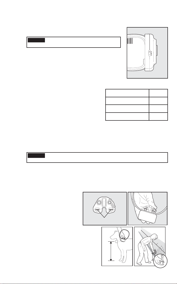
Place the Test Light Tool 6.
Contacts on the Contact
Points on the Receiver Collar
(6B,6C). Hold the Receiver
Collar at your dog’s neck
height with the Contact
Points pointing up (6D) and
the Correction Level Button
facing the Boundary Wire. Slowly
walk toward the Boundary Wire until
you hear the warning tone(6E). When
you hear the warning tone, you hav e
identifi ed the Boundary Width distance
(Static Correction Zone).
The Receiver Collar should NOT be on
your dog when the system is tested.
Amount of Wire Setting
Greater than 2400 feet
(6A)
to the A, B, or
Setting B is used
The following table
The receiver collar should not be on your dog when the system is
tested. Your pet may receive an unintended correction.
6B
Up to 1300 feet
1300 to 2400 feet
Test Light Contacts
6D
6A
A
B
C
6C
6E
Boundary
Wire
www.petsafe.net 19
Page 20
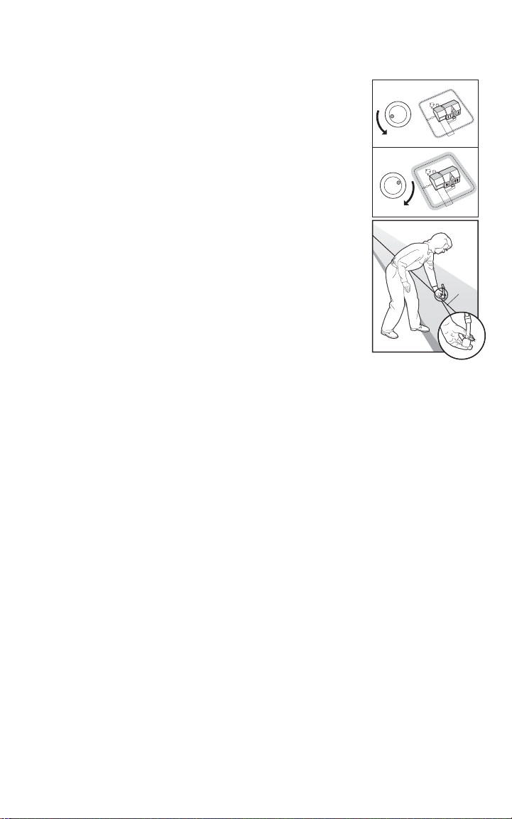
Two seconds after the warning tone, the test light will begin to fl ash. This fl ashing light can
aid you in identifying the Boundary Width should you have diffi culty hearing the tone. To
avoid having the Receiver Collar go into Ov er Correction Protection mode, w alk back into
the Pet Area until the beeping stops.
If the Receiver Collar does not beep at the desired range, adjust
the Boundary Width Control knob to obtain the desired range.
Turning the Boundary Width Control knob clockwise increases
the Boundary Width while turning it counterclockwise decreases
it (6F). Repeat this activity as needed until the Receiver Collar
6F
5
6
4
3
7
28
9
1
10
0
beeps between 6 to 10 feet from the Boundary Wire. If using a
Double Loop layout, y ou ma y need to increase the separation of the
Boundary Wire and/or increase the size of the Boundary Width to
achieve the desired range.
Test in a number of different locations around the containment area 7.
5
6
4
3
7
28
9
1
10
0
until you are satisfi ed that the system is functioning properly .
Next, walk all around the P et Area to ensure there are no areas 8.
6G
where the Receiver Collar may activate from signals coupled onto
buried wires or cables. Test the collar in and around the inside of
the house as well. As mentioned, cable and wires from cable TV,
electrical or telephone lines may conduct pet fencing signals inside
and outside the house that can activate the dog’ s collar accidentally.
Boundary
Wire
While rare, if this occurs your Boundary Wire is probably too close
to these outside lines and should be moved or modifi ed as shown in
Figure 3A.
To test the run-through prevention feature, walk towards the 9.
Boundary Wire. The Receiver Collar should tone and the Test Light
should fl ash brighter as you enter the run-through area (6G).
If you are satisfi ed that your system is functioning properly, you are ready to start burying the
Boundary Wire. If the Receiver Collar did not beep or the Test Light did not fl ash, see the
“Troubleshooting” section.
20 Customer Care Center 1-800-732-2677
Page 21
Step
Install the Boundary Wire
7
NOTICE
Before you begin installing the Boundary Wire, unplug the Fence
Transmitter power adapter from the Surge Protector or outlet.
To Bury the Boundary Wire
Burying the Boundary Wire is recommended to protect it and prevent disabling
the system.
Cut a trench 1. 1-3 inches deep along your planned boundary.
Place the Boundary Wire into the trench maintaining some slack to allow it to 2.
expand and contract with temperature variations.
Use a blunt tool such as a wooden paint stick to push the Boundary Wire into 3.
the trench. Be careful not to damage the Boundary Wire insulation.
To Attach the Boundary Wire to an
Existing Fence
The Boundary Wire of the PetSafe® Deluxe Little Dog In-Ground Fence™ can
be attached to a chain link fence, split rail fence, or a wooden privacy fence.
The Boundary Wire can be attached as high as needed. However, make sure the
Boundary Width is set at a high enough range for the pet to receive the signal. If
using a Double Loop with an existing fence at least fi ve feet tall, run the Boundary
Wire on top of the fence and return it on the bottom of the fence to get the fi ve
foot separation needed.
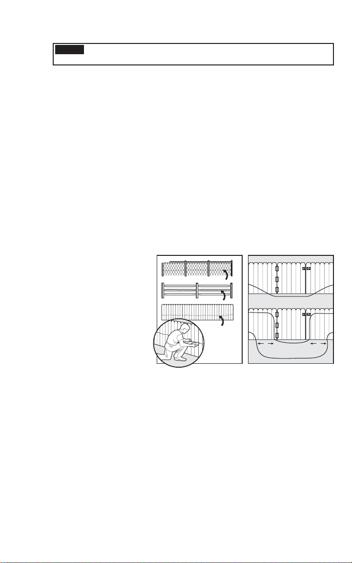
Chain Link Fence (7A):•
Weave Boundary Wire
through the links or use
plastic quick ties.
Wooden Split Rail or •
Privacy Fence (7A):
Use staples to attach
Boundary Wire. Av oid
puncturing the insulation
of the Boundary Wire.
Double Loop with an •
Existing Fence: Run
Boundary Wire on top of
the fence and return
it on the bottom of the fence to get the 5 foot separation needed.
Gate (Single Loop) (7B): • Bury the Boundary Wire in the ground across the gate
opening. Note: The signal is still active across the gate. Your pet cannot pass through an
open gate.
Gate (Double Loop) (7B): • Bury both Boundary Wires across the gate opening
while keeping them at least 5 feet apart.
7A
WEAVE WIRE INTO FENCE
STAPLE WIRE TO FENCE
STAPLE WIRE
TO FENCE
7B
SINGLE LOOP
5' 5'
DOUBLE LOOP
www.petsafe.net 21
Page 22
To Cross Hard Surfaces
(driveways, sidewalks, etc.)
Step
8
WARNING
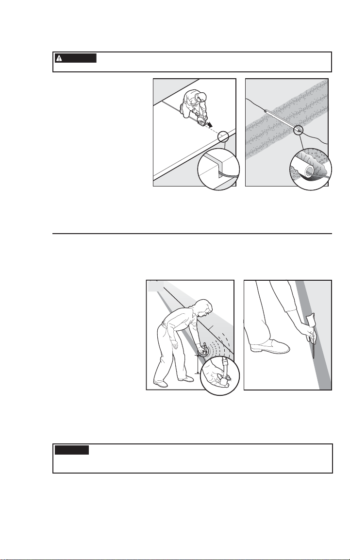
Concrete Driveway or •
Sidewalk (7C): Place
the Boundary Wire in a
convenient expansion
joint or create a groove
using a circular saw and
masonry blade. Place the
Boundary Wire in the
groove and cover with an
appropriate waterproofi ng
compound. For best
results, brush away dirt
or other debris before
patching.
Gravel or Dirt Driveway (7D):• Place the Boundary Wire in a PVC pipe or
water hose to protect the Boundary Wire before burying.
Follow all safety instructions for your power tools. Be sure to
always wear your safety goggles.
7C
7D
Place the Boundary Flags
The Boundary Flags are visual reminders for your pet of where the Warning Zone
is located.
Place the Test Light 1.
contacts on the
contact points and
hold the Receiver
Collar at your pet’s
neck height.
Walk towards the 2.
Warning Zone until
the Receiver Collar
beeps (8A).
Place a Boundary Flag 3.
in the ground (8B).
Walk back into the4.
Pet Area until the beeping stops.
Repeat this process around the Warning Zone until it is marked with Boundary 5.
Flags every 10 feet.
Note: If you cannot hear the beep, see the Test Light Instructions in Step 6.
8A
Boundary
Wire
8B
CAUTION
22 Customer Care Center 1-800-732-2677
To prevent an unintended corection, after the Boundary Flags have
been placed, be sure to set the static correction on the Receiver
Collar back to level 1 Tone Only.
Page 23
Step
Fit the Receiver Collar
Important: The proper fi t and placement of your Receiver Collar is important
for effective training. The Contact P oints m ust have direct contact with your
pet’s skin on the underside of his neck.
9
CAUTION
Please read and follow the instructions in this manual. Proper fi t of
the collar is important. A collar worn for too long or made too tight
on the pet’s neck may cause skin damage. Ranging from redness
to pressure ulcers; this condition is commonly known as bed sores.
Avoid leaving the collar on the dog for more than 12 hours•
per day.
When possible reposition the collar on the pet’s neck every•
1 to 2 hours.
Check the fi t to prevent excessive pressure; follow the •
instructions in this manual.
Never connect a lead to the electronic collar; it will cause •
excessive pressure on the contacts.
When using a separate collar for a lead, don’t put pressure on •
the electronic collar.
Wash the dog’s neck area and the contacts of the collar weekly •
with a damp cloth.
Examine the contact area daily for signs of a rash or a sore.•
If a rash or sore is found, discontinue use of the collar until the •
skin has healed.
If the condition persists beyond 48 hours, see your veterinarian.•
For additional information on bed sores and pressure necrosis, •
please visit our website.
These steps will help keep your pet safe and comfortable. Millions
of pets are comfortable while they wear stainless steel contacts.
Some pets are sensitive to contact pressure. You may fi nd after
some time that your pet is very tolerant of the collar. If so, you
may relax some of these precautions. It is important to continue
daily checks of the contact area. If redness or sores are found,
discontinue use until the skin has fully healed.
You may need to trim the hair in the area of the Contact Points.
Never shave the dog’s neck; this may lead to a rash or infection.
To assure a proper fi t, please follow these steps:
Turn the Receiver Collar battery to the1.
OFF position.
Start with your pet standing comfortably (2. 9A).
Place the Receiver Collar on your pet so that 3.
the battery module is pointing down. Center
the Contact Points underneath your pet’s neck,
touching the skin.
www.petsafe.net 23
9A
Page 24
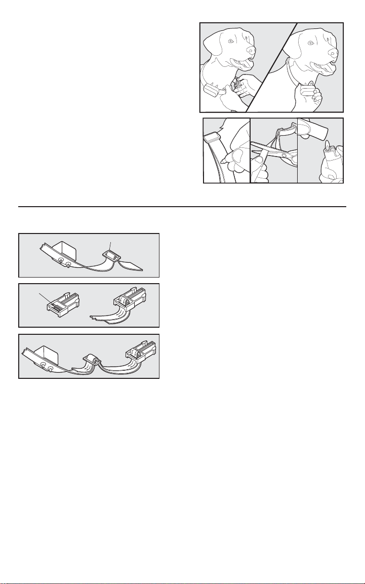
The Receiver Collar should fi t snugly, y et loose 4.
enough to allow one fi nger to fi t between a
contact point and your pet’s neck (9B). Allow
your pet to wear the collar for several minutes,
then re-check the fi t. Check the fi t again as your
pet becomes more comfortable with the
Receiver Collar.
Once you are satisfi ed with the fi t of the 5.
Receiver Collar then you may trim any excess
collar strap as follows (9C):
Mark the desired length of the Receiver a.
Collar with a pen. Allow for growth if your
pet is young or grows a thick winter coat.
Remove the Receiver Collar from your pet b.
and cut off the excess.
Before placing the Receiver Collar back c.
onto your pet, seal the edge of the cut
collar by applying a fl ame along the
frayed edge.
To Re-Thread the Collar
Slide Buckle
The slide buckle prevents the collar from
becoming loose around your pet’s neck.
Ridges
The ridges must be facing up; the collar will slip if
it is not properly threaded.
9B
9C
24 Customer Care Center 1-800-732-2677
Page 25

Training Guide
Be Patient With Your Pet
Important: Proper training of your pet is essential to the success of the
PetSafe® Deluxe Little Dog In-Ground Fence™. Read this section completely
before beginning to train your pet. Remember that the P etSafe® Deluxe Little
Dog In-Ground Fence
Have fun with your pet throughout the training process. Training should be fun, •
fair, fi rm and consistent.
Train for 10 to 15 minutes at a time. Don’t try to do too much too quickly. •
More-frequent short sessions are better than less-frequent longer sessions.
If your pet shows signs of stress, slow down the training schedule, add •
additional days of training, or increase the amount of play time with your pet in
the Pet Area. Common stress signals include:
Pet pulling on leash toward the house –
Ears tucked –
Tail down –
Body lowered –
Nervous / frantic movement or stiffening of pet’s body –
Your pet must be completely comfortable near the Boundary Flags at the end of •
every training session. Spend at least 5 minutes of “pla y time” at the completion of
each session within 10 feet of the Boundary Flags.
Finish each training session on a positive note with lots of praise and play.•
Remove the Receiver Collar after each training session.•
Be sure to contain your pet by another means during the training period (e.g. •
pen, tie-out, leash, etc.).
During training, if you need to take your pet out of the Pet Area, remove the •
Receiver Collar and either pick your pet up or put him in the car to pass out of
the Pet Area.
Even if you think your pet is responding well to the training, complete the entire •
training. Reinforcement is important!
™
is not a solid barrier.
Phase
1
www.petsafe.net 25
Day 1 - Boundary Awareness
Perform three training sessions per day, each lasting 10-15 minutes.
Goal:
To have your pet learn that the Boundary Flags and warning beep from the
Receiver Collar defi nes the new Pet Area.
Setup:
Program the Static Correction Level on the Receiver Collar to Level 1 Tone •
Only training mode.
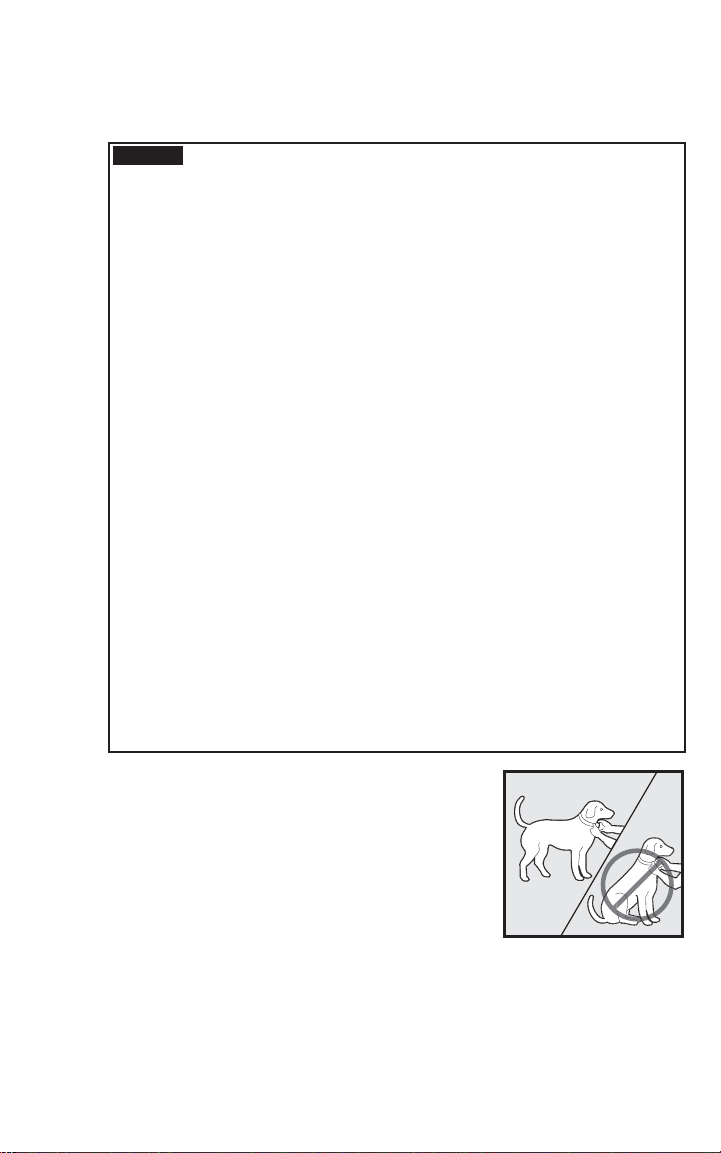
Put a separate non-metallic collar on your pet’s neck ABOVE the Receiver •
Collar and attach a leash.
CAUTION
Have tiny pieces of treats that your pet will fi nd desirable available (hot dogs or •
lunch meat work well).
Have your pet’s favorite play toy available.•
Be sure the extra collar does not put pressure on the
Contact Points.
Page 26

Steps:
Begin by walking your pet on a leash in the Pet Area. Calmly praise and talk 1.
to your pet.
Move toward the Boundary Flags (2. 10A). Keep your mood happy.
With full control of your pet on a leash, walk to the fl ags. As your pet enters the 3.
Static Correction Zone, the Receiver Collar will begin to beep (10B). Allo w your
pet to stay in the Static Correction Zone for up to 2 seconds then gently help him
back into the Pet Area (10C). Immediately praise and offer your pet a treat as he
enters the Pet Area, even if you have helped with the leash.
Repeat this process at the same Boundary Flag until your pet resists going into 4.
the Static Correction Zone.
Aim to master 3-4 Boundary Flags per session. Make this FUN! Praise if 5.
your pet quickly retreats or resists going into the
Static Correction
Zone.
Phase
2
10A 10C
10B
Days 2 thru 4 - Continue Boundary
Awareness
Perform three training sessions per day, each lasting 10-15 minutes.
Goal:
To train your pet to stay in the Pet Area and respect the boundary.
Setup:
Program the Static Correction Level on the Receiver Collar to Level 2.•
Put a separate non-metallic collar on your pet’s neck ABOVE the Receiver •
Collar and attach a leash.
CAUTION
Have tiny pieces of treats available (hot dogs or lunch meat work well).•
Have your pet’s favorite play toy available.•
Steps:
Repeat steps 1-5 in Phase One.1.
If y2.
Receiver Collar is fi tting properly according to Step 9 on page 23.
If the Receiver Collar is fi tted properly and your pet does not respond to the 3.
Static Correction, increase the Static Correction Level by 1. Watch for slight
reactions at fi rst such as ears up, head turned, looking at the ground.
Stay at the same fl ag until your pet resists going into the 4. Static
Correction Zone.
Be sure the extra collar does not put pressure on the
Contact Points.
our pet does not respond to the Static Correction, confi rm that the
26 Customer Care Center 1-800-732-2677
Page 27

Phase
3
Days 5 thru 8 - Distraction Phase
Perform three training sessions per day, each lasting 10 to 15 minutes.
Goal:
To train your pet to stay within the Pet Area with distractions outside of the Pet Area.
Setup:
Program the Static Correction Level on the Receiver Collar to level 2 or higher •
depending on the reaction results from days 2 thru 4.
Put a separate non-metallic collar on your pet’s neck ABOVE the Receiver Collar •
and attach a leash.
CAUTION
Have tiny pieces of treats av ailable (hot dogs or lunch mea t w ork well).•
Have your pet’s favorite play toy available.•
Create distractions to tempt your pet to enter the Static Correction Zone,•
such as:
Have a family member cross from inside the Pet Area to outside of it. –
Throw a ball or treat outside of the Pet Area. –
Have a neighbor walk their pet outside of the P et Area. –
Gradually increase distraction level.•
Never coax or call your pet out of the pet area.
Steps:
With full control of your pet on a leash, hav e the distraction presented. 1.
If your pet does not move toward the distraction, praise and offer a treat. 2.
If your pet does react to the distraction, allow him to go into the Static3.
Correction Zone.
Help your pet back into the Pet Area if he does not turn back after 2 seconds. 4.
Treat and praise y our pet anytime he comes back into the Pet Area with or 5.
without help.
Repeat this process with other distractions. Use other family members during6.
this process.
If y7.
Collar is fi tting properly according to Step 9 on page 23 .
If the Receiver Collar is fi tted properly and if your pet does not respond to the 8.
Static Correction, increase the Static Correction Level by 1.
Be sure the extra collar does not put pressure on the
Contact Points.
our pet does not respond to the Static Correction, confi rm that the Receiver
www.petsafe.net 27
Page 28
Phase
4
Days 9 thru 14 - Unleashed
Supervision
Training sessions should start at 10-15 minutes, gradually increasing to over
an hour.
Your pet is ready for this step only when he clearly avoids the entire
Correction Zone
do not leave your pet unattended.
Goal:
To give your pet free run of the Pet Area off the leash.
Setup:
Adjust the Receiver Collar to the permanent setting
appropriate for your pet.
Steps:
Enter the Pet Area with your pet wearing the 1.
Receiver Collar.
Walk around the yard and play with your pet, staying 2.
within the Pet Area a t all times.
Preoccupy yourself with another task in the yard 3.
while watching your pet.
Should your pet escape, take the Receiver Collar off 4.
and lead him back into the Pet Area.
, regardless of any distractions or temptations. During this step,
Static
Phase
5
Days 15 thru 30 - Pet Monitoring
Your pet is ready to run! Check in on your pet at regular intervals.
Note: After you are satisfi ed your pet’s training is complete, remove every other Boundary
Flag every 4 days until all fl ags are removed. Save Boundary Flags for future use.
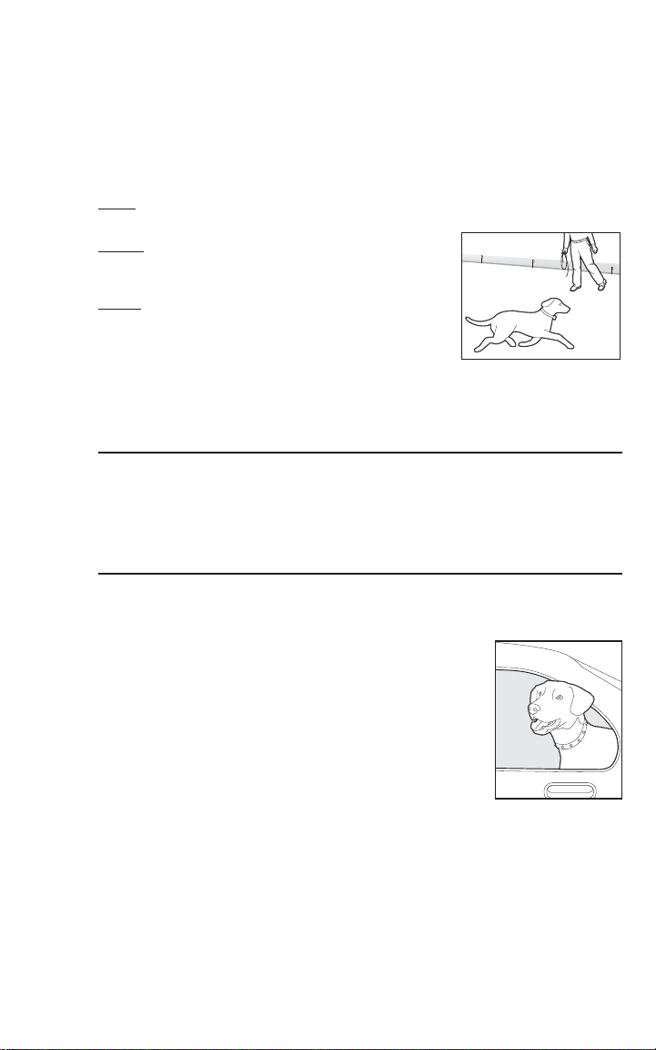
Taking Your Pet Out of the Pet Area
Important: Remove the Receiver Collar and leave it in the Pet Area.
Once your pet learns the Boundary Zone, he will be
reluctant to cross it for walks or car rides.
Option 1: Replace the Receiver Collar with a regular collar.
Put your pet in a car that is within the Pet Area and drive
him out of the Pet Area.
Option 2: Replace the Receiver Collar with a regular collar
and leash. Walk your pet out of the Pet Area while giving a
command such as “OK” at a specifi c place of the Boundary
Zone (the end of your driveway, sidewalk, etc.). Always
leave the Pet Area with a leash at this place and your pet
will associate leaving the Pet Area only on a leash, only at
this place, and only with a person. You may initially need to
convince your pet to leave the Pet Area with a food treat and
lots of praise.
Note: You may also carry your pet out of the Pet Area.
Congratulations! You hav e now successfully
completed the training program.
28 Customer Care Center 1-800-732-2677
Page 29

Accessories
To purchase additional accessories for your PetSafe® Deluxe Little Dog In-Ground Fence™,
contact the Customer Care Center at 1-800-732-2677 or visit our website at
www.petsafe.net to locate a retailer near you.
Component Part Number
Battery RFA-188
Power Adapter for the Fence Transmitter (USA and Canada) RFA-372
Power Adapter for the Fence Transmitter (Australia and NZ) 650-183
Surge Protection Kit (USA and Canada) LP-4100-1
Replacement Collar RFA-402
Additional Receiver Collar PIG00-10778
Stubborn Dog Receiver Collar PRF-275-19
Additional Boundary Wire RFA-1
Additional Boundary Flags RFA-2
Additional Gel-fi lled Capsules and Wire Nuts RFA-366
Wire & Flag Accessory Kit PRFA-500
Long Contact Points RFA-415
Fence T ransmitter RFA-435
Wire Break Locator RFA-50
www.petsafe.net 29
Page 30
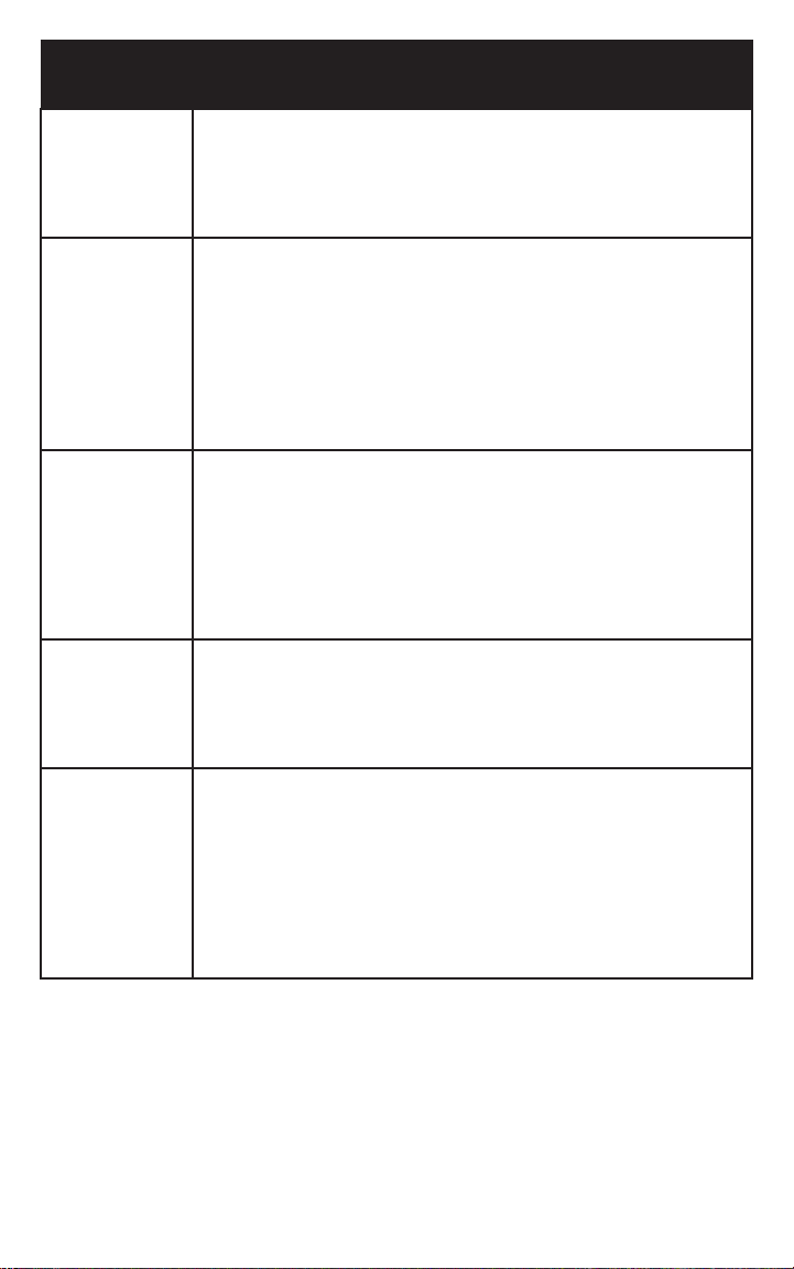
Troubleshooting
Receiver
Collar is not
beeping or
correcting.
The Receiver
Collar is
beeping, but
the pet is not
responding
to the Static
Correction.
The Receiver
Collar has
to be held
on top of the
Boundary Wire
to activate.
The Receiver
Collar
activates inside
the house.
I have an
inconsistent
signal.
Check battery to make sure it is installed properly and turned to the •
ON position.
Perform Static Correction and Battery Test (page 17). If Battery Status •
LED does not fl ash Green, replace the battery.
Check that both lights are lit on the Fence Transmitter. If not, perform •
the “Transmitter Loop Test” (page 33).
Test the Receiver Collar with the Test Light walking toward the •
Boundary Wire.
If the Test Light fl ashes, check the fi t of the Receiver Collar.•
Trim your pet’s fur where the Contact Points touch the neck and/or •
purchase longer Contact Points by contacting the Customer
Care Center.
Increase the Static Correction Level.•
Repeat training steps to reinforce training. •
Purchase a stronger Receiver Collar by contacting the Customer•
Care Center.
Perform Battery Test and replace battery if necessary.•
Adjust Boundary Width Control knob clockwise to increase the •
distance from the Boundary Wire tha t the Receiver Collar activates.
Verify the Boundary Control Switch is placed at the proper setting
according to the amount of Boundary Wire used. (See Step 6)
If using a Double Loop, make sure Boundary Wires are separated at •
least 5 feet.
If the Receiver Collar still has to be held on top of the Boundary Wire, •
perform the “System Test” and/or “Transmitter Loop Test”.
Make sure the Boundary Wire is not running within 15 feet of the •
house. The signal can transmit through the walls of your house.
Make sure Boundary Wires are twisted from Boundary to the•
Fence T ransmitter.
Turn the Boundary Width Control knob counterclockwise to decrease •
the distance from the Boundary Wire that the Receiver Collar activates.
Make sure Fence T ransmitter is a t least 3 feet from large metal objects •
or appliances.
Make sure all Boundary Wire turns are gradual with a minimum•
3 foot radius.
Make sure the Boundary Wire is not running parallel to and within•
10 feet of electrical wires, neighboring containment systems, telephone
wires, television or antenna cables, or sa tellite dishes.
If a neighboring containment system may be causing an inconsistent •
signal, move the Boundary Wire farther away from the neighboring
containment system.
30 Customer Care Center 1-800-732-2677
Page 31

The Power and
Loop Indicator
Lights are off.
The Power
Light is on, the
Loop Indicator
Light is off,
and the Fence
Transmitter
loop alarm is
sounding.
The fuse
blows when it
is replaced.
(Australia &
New Zealand
only)
Check that the Pow er Adapter is plugged into the Fence Transmitter. •
Check that the Pow er Adapter and/or Surge Protector are plugged•
in properly.
If the system is plugged into a GFCI or RCD outlet, check to see if the •
circuit has been tripped. Reset the GFCI or RCD circuit if required.
Verify that the outlet is working properly by plugging in a known •
working item such as a radio.
If a Surge Protector is installed, unplug the Surge Protector and plug •
the power adapter directly into the outlet. If the Transmitter operates
without the Surge Protector, contact the Customer Care Center for a
replacement Surge Protector.
Check Boundary Wire connections a t the Fence Transmitter and/or Surge •
Protector for proper connection.
Check for broken or damaged Boundary Wires a t outside entry to•
the house.
Perform the “Transmitter Loop Test” (page 33) to determine if the •
Fence T ransmitter needs to be replaced.
If the Fence T ransmitter is functioning properly, you hav e a break in •
your Boundary Wire. See the “Wire Break Location Test” (page 34)
section in this guide.
The Fence T ransmitter and/or Power Adapter needs to be replaced. •
Contact the Customer Care Center.
Additional Information
Use care when using a weed eater or when digging near the Boundary Wire to•
prevent damage.
The system should only be used with healthy pets. Contact your veterinarian if you•
have concerns about the medical condition of your pet (medication, pregnant, heart
conditions, etc.).
The PetSafe•
The Static Correction will get your pet’s attention, but will not cause harm. It is designed •
to startle, not to punish.
Test the Receiver Collar at least once a month to verify that it is functioning properly. •
Check that it activates at the Boundary Wire. Battery life depends upon how often the
Receiver Collar is activated.
Remove the Receiver Collar from your pet when indoors for the comfort of your pet.•
Never leave the Receiver Collar on your pet for more than 12 consecutive hours.•
®
Deluxe Little Dog In-Ground Fence™ is for residential use only.
www.petsafe.net 31
Page 32

System T est
The system test is used to determine the cause of system problems that have not been
addressed elsewhere in this guide. You will need a 10 foot piece of Boundary Wire with
3
⁄8 inch of insulation removed from each end to use as a test loop wire. Follow the steps
below to perform the system test:
Re1. move the Receiver Collar from you dog and make sure it is turned on with a good
battery installed.
Unplug the Power Adapter from the Fence Transmitter Power Jack. 2.
Set the Boundary Control switch to B.3.
Set the Receiver Collar Static Correction Level to 5.4.
Disconnect the twisted Boundary Wire from the Boundary Wire terminals on the5.
Fence Transmitter by pressing the red release levers on the connector and pulling the
wires free.
Insert the two ends of the test loop wire into the Boundary Wire Terminals on6.
the transmitter.
Plug the Power Adapter into Fence Transmitter Power Jack.7.
Note the original position of the Boundary Width Control knob and turn the Boundary 8.
Width control knob to 10 and then back to 5.
Place the Test Light Tool Contacts on the Contact Points of the Receiver Collar. While 9.
holding the Receiver Collar with the Test Light Tool in place, start outside of the test
loop and walk toward the loop. Make a mental note of the distance between you and the
wire when the Receiver Collar activates.
Turn the Boundary Width Control knob to 10 and repeat Step 9. The distance where 10.
the Receiver Collar activates should be greater than that of Step 9.
If more than one Receiver Collar is used on the system, repeat the above test on each 11.
collar.
Interpreting the Results:12.
If the Power light or the Loop indicator light are not both lit on the Fence a.
transmitter, or the alarm is on, there is a problem with the transmitter. Contact
the Customer Care Center. (Australia and New Zealand only: Check and
replace the Fence Transmitter fuse if necessary. If replacing the fuse does
not correct the problem, there is a problem with the transmitter. Contact the
Customer Care Center.)
If both the Power and Loop indicator lights are on, but the Receiver Collar b.
does not activate on the test loop wire, the Receiver Collar is not working.
Contact the Customer Care Center.
If both the Power and Loop indicator lights are on and the Receiver Collar is c.
activating at different distances on the test loop wire, the problem is either in
the containment Boundary Wire or the Surge Protector. (USA and Canada
Only: Reconnect the transmitter wires to the Surge Protector and connect the
test loop to the Surge Protector Loop terminals. Repeat steps 7 through 10.)
If both the Power and Loop indicator lights are on and the Receiver Collar is activating 13.
at different distances on the test loop wire, the problem is in the containment Boundary
Wire. Perform the Wire Break Location Test. (USA and Canada Only: If the Loop
indicator light is off with an alarm on the Fence Transmitter, there is a problem with the
Surge Protector. Contact the Customer Care Center.)
When testing is complete, return the Boundary Control Switch and the Boundary 14.
Width Control setting to their original position.
Repeat the Boundary Width testing from Step 6 on Page 19 until you achieve the 15.
desired Boundary Width between 12 to 20 feet.
32 Customer Care Center 1-800-732-2677
Page 33
Transmitter Loop Test (USA and Canada)
The Transmitter Loop Test is a simple test to determine the cause of a “Boundary Wire
Broken or Disconnected” alarm indication. You will need a short 10 foot piece of Boundary
Wire with 3⁄8 inch of insulation stripped from both ends.
CAUTION
Verify the transmitter is plugged into the Surge Protector and all Boundary Wire connections
at the Surge Protector and transmitter are properly connected. If the transmitter Power light
is on, the Loop indicator light is off, and the alarm is on, continue with the following steps:
Re1. move the twisted wire from the Surge Protector Loop connector by pressing the red
release levers on the connector and pulling the wires free.
Insert both ends of the 10 foot piece of wire into the Loop connector on the Surge 2.
Protector and recheck the transmitter Loop light and alarm.
Remove the twisted wire from the Fence Transmitter Boundary Wire terminals by 3.
pushing the red release levers and pulling the wires free.
Insert both ends of the 10 foot wire loop into the Transmitter Boundary Wire Terminals 4.
and recheck the transmitter Loop indicator light and alarm.
Contact the Customer Care Center for assistance.5.
The receiver collar should not be on your dog when the system is tested.
Your pet may receive an unintended correction.
If the Loop indicator light is green and the alarm is off, there is a problem with a.
the Boundary Wire. Check for visible damage to the wire at the entry into the
house. If none is observed, perform the Wire Break Location Test to fi nd and
correct the wire break in your Boundary Loop.
If the Loop indicator light is still off and the alarm is on, remove the 10 b.
foot piece of wire, reconnect the Boundary Wire to the Surge Protector and
continue with the following steps.
If the loop indicator light is green and the alarm is off, there is a problem with a.
the Surge Protector. Contact the Customer Care Center for assistance.
If the Loop indicator light is still off and the alarm is on, there is a problem b.
with the Fence Transmitter.
Transmitter Loop Test (Australia and
New Zealand)
The Transmitter Loop Test is a simple test to determine the cause of a “Boundary Wire
Broken or Disconnected” alarm indication. You will need a short 10 foot piece of Boundary
Wire with 3⁄8 inch of insulation stripped from both ends.
CAUTION
Verify the transmitter is plugged into the AC power outlet and all Boundary Wire connections
at the transmitter are properly connected. If the transmitter Power light is on, the Loop
indicator light is off, and the alarm is on, continue with the following steps:
Remove the twisted wire from the Fence Transmitter Boundary Loop terminals by 1.
pushing the red release levers on the connector and pulling the wires free.
Insert both ends of the 10 foot wire loop into the Boundary Loop Terminals and 2.
recheck the transmitter Loop indicator light and alarm.
Contact the 3. Customer Care Center for assistance.
www.petsafe.net 33
The receiver collar should not be on your dog when the system is tested.
Your pet may receive an unintended correction.
If the Loop indicator light is green and the alarm is off, there is a problem with a.
the Boundary Wire. Check for visible damage to the wire at the entry into the
house. If none is observed, perform the Wire Break Location Test to fi nd and
correct the wire break in your Boundary Loop.
If the Loop indicator light is still off and the alarm is on, there is a problem b.
with the Fence Transmitter.
Page 34

Wire Break Location Test
Please follow these steps in determining where you have a break in your Boundary Wire:
Locate your original splice(s) and verify they have a good, solid connection.1.
Check your yard to determine any possible damage to the Boundary Wire (e.g. recent 2.
digging, aerating, rodent burrowing, or any other noticeable disturbance in your y ard next
to the Boundary Wire).
If you still cannot fi nd the break in the Boundary Wire, there are two options for locating it:
Option 1: Contact the Customer Care Center to purchase a Wire Break Locator that will
locate the break in the Boundary Wire.
Option 2: Follow the procedure below:
Unplug the Fence T ransmitter.1.
Connect both ends of your twisted Boundary Wire to one Loop Wire Terminal.2.
Measure and cut a Test Wire which is half the length of your total Boundary Wire footage.3.
Connect one end of Test Wire to the other Loop Wire Terminal.4.
Locate the halfway point of your boundary and cut the Boundary Wire.5.
Splice the other end of the Test Wire to either side of your Boundary Wire where y ou cut 6.
it in half.
Plug in the Fence T ransmitter and check the Loop Indica tor Light. If the Loop7.
Indicator Light glows solid green, you can assume the break is in the other half of the
Boundary Wire.
If the Loop Indicator Light is off and the alarm sounds, you may assume there is a break 8.
in this portion of the Boundary Wire. However, there is a small chance of having more
than one break in your system. Be sure to check both halves of y our entire loop.
Replace the damaged Boundary Wire with new Boundary Wire.9.
Reconnect the Boundary Wire to the Fence Transmitter.10.
Check the Loop Indicator Light. If the Loop Indicator Light glows solid green, test the 11.
system with the Receiver Collar.
Terms of Use and Limitation of Liability
Terms of Use 1.
This Product is offered to you conditioned upon your acceptance without modifi cation
of the terms, conditions and notices contained herein. Usage of this Product implies
acceptance of all such terms, conditions, and notices.
Proper Use 2.
This Product is designed for use with pets where training is desired. The specifi c
temperament of your pet may not work with this Product. If you are unsure whether
this is appropriate for your pet, please consult your veterinarian or certifi ed trainer.
Proper use includes reviewing the entire Guide provided with your Product and any
specifi c Caution statements.
No Unlawful or Prohibited Use 3.
This Product is designed for use with pets only. This pet training device is not intended to
harm, injure or provoke. Using this Product in a w a y tha t is not intended could result in
violation of Federal, Sta te or local laws.
Limitation of Liability 4.
In no event shall Radio Systems® Corporation be liable for any direct, indirect, punitive,
incidental, special or consequential damages, or any damages whatsoever arising out of or
connected with the use or misuse of this Product. Buyer assumes all risks and liability from
the use of this Product.
Modification of Terms and Conditions 5.
Radio Systems® Corporation reserves the right to change the terms, conditions and notices
under which this Product is offered.
34 Customer Care Center 1-800-732-2677
Page 35

Compliance
FCC/Canada
This Class B digital apparatus complies with Canadian ICES-003. This equipment has been
tested and found to comply with the limits for a Class B digital device, pursuant to Part
15 of the FCC Rules. These limits are designed to provide reasonable protection against
harmful interference when the equipment is operated in a residential environment. This
equipment generates, uses, and can radia te radio frequency energy and, if not installed and
used in accordance with the instruction guide, may cause harmful interference to radio
communications. Ho wever, there is no guarantee that interference will not occur in a practical
installation. If this equipment causes harmful interference to radio or television reception,
which can be determined by turning the equipment off and on, the user is encouraged to try to
correct the interference by one or more of the following measures:
Relocate the interfered receiving antenna.•
Increase the separation between the equipment and receiver.•
Connect the equipment into an outlet on a circuit different to that to which the receiver is •
connected.
Contact the Customer Care Center at 1-800-732-2677.•
This device complies with Industry Canada Rules. This device complies with part 15 of
the FCC Rules. Operation is subject to the following two conditions: (1) This device may
not cause harmful interference, and (2) this device must accept any interference received,
including interference that may cause undesired operation.
Unauthorized changes or modifi cations to the equipment, not approved by Radio Systems
Corporation, could result in not meeting compliance with FCC regulations and could void
the user’s authority to operate the equipment.
Australia
This device complies with the applicable EMC requirements specifi ed by the ACMA
(Australian Communications and Media Authority).
®
Customer Care International
USA & Canada - Tel: 800-732-2677
Monday - Friday 8 AM - 8 PM / Saturday 9 AM – 5 PM
Australia - Tel: 1800 786 608
Monday - Friday 9 AM - 5 PM
New Zealand - Tel: 0800 543 054
Monday - Friday 12 PM - 7 PM
This product has the benefi t of a limited manufacturer’s warranty. Details of the warranty
applicable to this product and its terms can be found at www.petsafe.net and/or are available
by sending a stamped addressed envelope to PetSafe® Ltd. Redthorn House, Unit 9, Chorley
West Business Park, Ackhurst Road, Chorley, Lancashire PR7 1NL, United Kingdom.
Perchlorate Battery
Perchlorate Material – special handling may apply.
See www.dtsc.ca.gov/hazardouswaste/perchlorate.
www.petsafe.net 35
Page 36
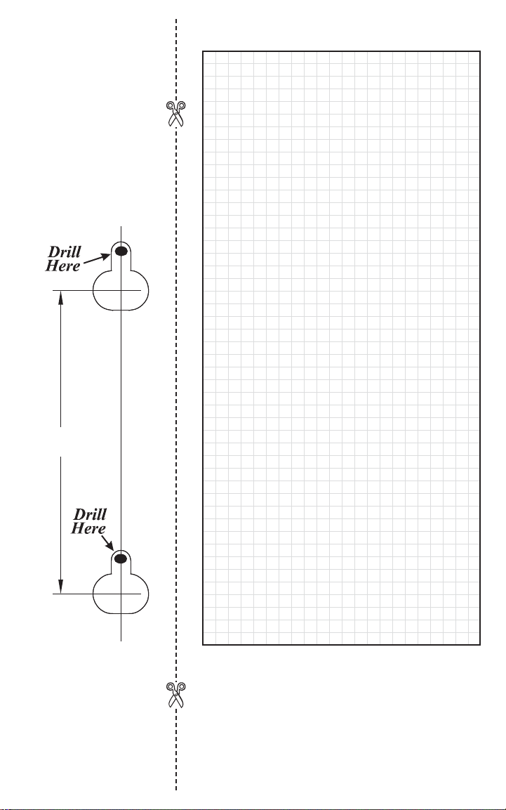
Mounting
Template
3.000"
(7.62 cm)
Layout Grid
Radio Systems® Corporation
10427 Electric Avenue
Knoxville, TN 37932
1-800-732-2677
Protected by US Patents 6,921,089, 7,541,937,
and D531,117. Other patents pending.
©2007 Radio Systems Corporation
www.petsafe.net
400-1188/1
 Loading...