

Petsafe PIF00-13651 Operating And Training Manual

mapping fence
Model Number
PIF00-13651
wireless
operating and training guide
PLEASE READ THIS ENTIRE GUIDE BEFORE BEGINNING

2 1-800-732-2677

Thank you for choosing PetSafe® brand. You and your pet deserve a companionship that includes
memorable moments and a shared understanding together. Our products and training tools
promote a lifestyle of protection, teaching, and love — essentials that influence memories for a
lifetime. If you have any questions about our products or training your pet, please visit our website
at www.petsafe.net or contact our Customer Care Center at 1-800-732-2677.
To get the most protection out of your warranty, please register your product within 30 days
at www.petsafe.net. By registering and keeping your receipt, you will enjoy the product’s full
warranty and should you ever need to call the Customer Care Center, we will be able to help you
faster. Most importantly, we will never give or sell your valuable information to anyone. Complete
warranty information is available online at www.petsafe.net.
www.petsafe.net 3
Important Safety Information
Explanation of Attention Words and Symbols used in this guide
This is the safety alert symbol. It is used to alert you to potential personal injury hazards. Obey all safety messages that
follow this symbol to avoid possible injury or death.
WARNING indicates a hazardous situation which, if not avoided, could result in death or serious injury.
CAUTION, used with the safety alert symbol, indicates a hazardous situation, which, if not avoided could
result in minor or moderate injury.
CAUTION, used without the safety alert symbol, indicates a hazardous situation which, if not avoided, could
result in harm to your pet.
NOTICE is used to address safe use practices not related to personal injury.
• Not for use with aggressive dogs. Do not use this product if your dog is prone to aggressive behavior.
Aggressive dogs can cause severe injury or death to their owners and others. If you are not sure that this
product is right for your dog, please talk to your veterinarian or a certified trainer.
• Risk of electric shock. Use the Fence Transmitter indoors in dry location only.
Allowing your pet to wear the Receiver Collar indoors may result in accidental activation of the
Receiver Collar.
While physically close to the outside door:
PET LEAVING THE HOUSE:
1. Place Receiver Collar on your pet and fit it correctly with the PetSafe logo upright facing towards
your dog’s chin, and facing away from your dog’s body as shown in Figure 10B on page 23.
2. Turn ON the Receiver Collar by holding the MODE button down until a 2 beep tone sounds and a green
LED comes ON. Release the button. The Receiver Collar is now ON. The green light should flash every 4
seconds.
3. Allow your pet to go outside in the Pet Area.
4. Do not allow your pet to roam inside the house with the Receiver Collar turned ON.
As close as possible to the outside door:
PET ENTERING THE HOUSE:
1. Remove the Receiver Collar or
2. Turn OFF the Receiver Collar by pressing and holding down the MODE button for 5 seconds. The Red
LED will be on during this time. The Red LED will then turn OFF with a 2 beep sound. All Receiver LED’s
will stay OFF indicating that the Receiver is OFF.
4 1-800-732-2677

• This PetSafe® Wireless Mapping Fence is NOT a solid barrier. The system is designed to act as a deterrent
to remind pets by Static Correction to remain in the boundary established. It is important that you
reinforce training with your pet on a regular basis. Since the tolerance level to Static Correction varies
from pet to pet, Radio Systems® Corporation CANNOT guarantee that the system will, in all cases, keep a
pet within the established boundary. Not all pets can be trained to avoid crossing the boundary! Therefore,
if you have reason to believe that your pet may pose a danger to others or harm himself if he is not kept
from crossing the boundaries, you should NOT rely solely upon the PetSafe® Wireless Mapping Fence to
confine your pet. Radio Systems® Corporation shall NOT be liable for any property damage, economic
loss or any consequential damages, sustained as a result of any animal crossing the boundary.
• Proper fit of the collar is important. A collar worn for too long or made too tight on the pet’s neck may
cause skin damage. Ranging from redness to pressure ulcers; this condition is commonly known as bed
sores.
- Avoid leaving the collar on the dog for more than 12 hours per day.
- When possible reposition the collar on the pet’s neck every 1 to 2 hours.
- Check the fit to prevent excessive pressure; follow the instructions in this manual.
- Never connect a lead to the electronic collar; it will cause excessive pressure on the contacts.
- When using a separate collar for a lead, don’t put pressure on the electronic collar.
- Wash the dog’s neck area and the contacts of the collar weekly with a damp cloth.
- Examine the contact area daily for signs of a rash or a sore.
- If a rash or sore is found, discontinue use of the collar until the skin has healed.
- If the condition persists beyond 48 hours, see your veterinarian.
- For additional information on bed sores and pressure necrosis, please visit our website.
These steps will help keep your pet protected and comfortable. Millions of pets are comfortable while they
wear stainless steel contacts. Some pets are sensitive to contact pressure. You may find after some time
that your pet is very tolerant of the collar. If so, you may relax some of these precautions. It is important to
continue daily checks of the contact area. If redness or sores are found, discontinue use until the skin has
fully healed.
• You may need to trim the hair in the area of the Contact Points. Never shave the dog’s neck; this may lead
to a rash or infection.
• Always remove your dog’s Receiver Collar before performing any Transmitter testing.
• Turn off power before changing Mode Selection Switch setting on Transmitter.
• The Receiver Collar should not be on your dog when the system is tested. Your pet may receive an
unintended correction.
• To prevent unintended corrections to your pet, test the system whenever making any adjustments to the
distance of your Warning Zone.
• If you use a collar and leash for training, be sure the extra collar does not put pressure on the contact
points.
• Never remove power from the system when the collar is on the pet. This may activate the Receiver Collar.
• Radio Systems® Corporation recommends the use of an Uninterruptible Power Supply (UPS) for use with
your wireless fence. Should the power go out at your home, your pet will be unprotected. Power outages
can be unpredictable, and the use of a UPS will provide you with some time to properly restrain your pet.
• To prevent an unintended correction, after the Boundary Flags have been placed, be sure to set the static
correction on the Receiver Collar back to level 1 tone only.
• Do not charge your Receiver Collar every night. Charging too often can reduce battery life. Charge your
Receiver Collar when the Receiver Indicator Light blinks red/green; or when the light blinks red.
• Do not place anything on the top of the Transmitter or cover any ventilation holes. This may overheat the
Transmitter and cause early transmit failure.
• Do not place Transmitter in a closet or any other confined, unventilated area.
www.petsafe.net 5

Table of Contents
Components ........................................................................................................................................................................................7
Other Items You May Need ................................................................................................................................................................7
How the System Works .......................................................................................................................................................................8
Key Definitions ....................................................................................................................................................................................8
Operating Guide .................................................................................................................................................................10
Lay out the System .........................................................................................................................................................................10
Charge the Receiver Collar ............................................................................................................................................................14
Prepare the Receiver Collar ...........................................................................................................................................................14
Prepare the Boundary Programming Unit .....................................................................................................................................17
Prepare the Receiver Collar for Programming ...............................................................................................................................18
Place Boundary Flags and Test Layout ..........................................................................................................................................19
Place Fence Transmitter ................................................................................................................................................................. 19
Conduct Boundary Flag Test ..........................................................................................................................................................19
Conduct Boundary Scan Test and Place Flags ............................................................................................................................... 19
Install the Fence Transmitter .......................................................................................................................................................... 20
Program the Boundary ...................................................................................................................................................................21
Set the Warning Zone ....................................................................................................................................................................21
Fit the Receiver Collar ....................................................................................................................................................................23
Training Guide ...................................................................................................................................................................... 25
Be Patient With Your Pet................................................................................................................................................................25
Day 1 - Boundary Awareness .........................................................................................................................................................26
Days 2 thru 4 - Continue Boundary Awareness .............................................................................................................................26
Days 5 thru 8 - Distraction Phase ...................................................................................................................................................27
Days 9 thru 14 - Unleashed Supervision ........................................................................................................................................27
Days 15 thru 30 - Pet Monitoring ..................................................................................................................................................28
Taking Your Pet Out of the Pet Area ..............................................................................................................................................28
Accessories ....................................................................................................................................................................................29
Frequently Asked Questions ...................................................................................................................................29
Terms of Use and Limitation of Liability ............................................................................................................................................ 33
Compliance .......................................................................................................................................................................................34
Customer Care International .............................................................................................................................................................34
Warranty ............................................................................................................................................................................................35
Claims Procedure ..............................................................................................................................................................................35
6 1-800-732-2677
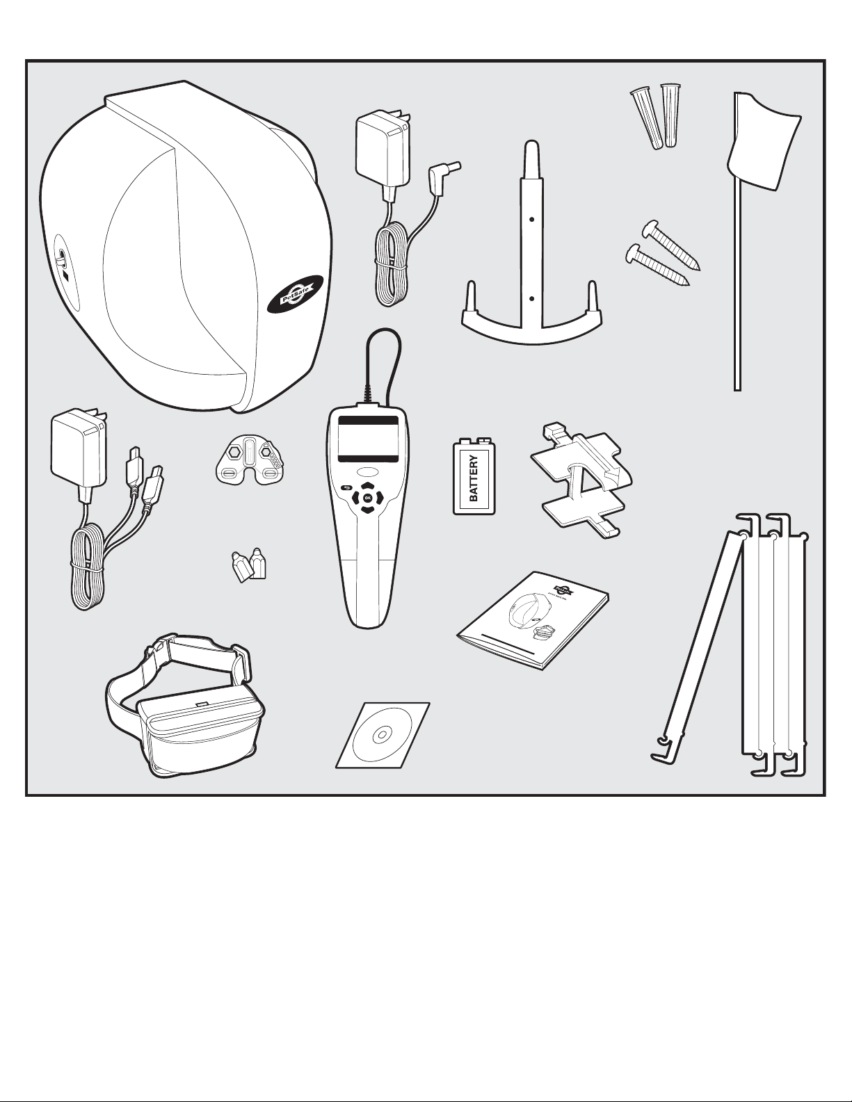
Components
Receiver
Collar
with
Short
Contact
Points
Receiver
Charger
(6 ft.)
Transmitter
Test Light
Tool
Long Contact
Points (2)
Transmitter
Adapter
Boundary
Programming Unit
T
I
A
O
L
N
L
A
D
T
V
S
D
N
I
Installation
Power
(12 ft.)
Transmitter
Mounting Bracket
9-Volt Alkaline
Battery
boundary mapping
wireless fence
o
PLEASE
perati
ng
RE
A
and
D THIS
ENT
IRE
GUID
Operating and
Training Guide
DVD
Mounting
Anchors (2)
Mounting
Screws (2)
Boundary Flags (130)
Receiver
Mounting
Bracket
Receiver
Handle
M
o
de
PIF00-13651
l
Nu
mber
t
ra
i
nin
g
g
ui
de
E
BE
F
ORE BEGINNING
Other Items You May Need
• Phillips screwdriver
• Scissors
• Lighter
• Drill
• Tape Measure
• Non-metallic collar and leash
Set up and training help: www.petsafe.net/fence
IMPORTANT: Fully charge the Receiver Collar (about 2-3 hours) before beginning to program the boundary.
www.petsafe.net 7

How the System Works
The Wireless Mapping Fence allows you to set custom boundaries for your dog by programming the shape and
location of the Pet Area. After positioning Boundary Flags to define the Pet Area, the Boundary Programming
Unit (BPU) is used to collect boundary data and program the Receiver Collar. The Receiver Collar offers 5 levels of
correction plus tone-only, adjustable to your dog’s temperament. If you have multiple dogs, you can easily download
boundary data into multiple Receiver Collars.
The Fence Transmitter is centrally located and transmits a radio signal up to 90 feet in all directions. The Receiver
Collar monitors your dog’s location and issues a warning tone if your dog approaches the Warning Zone. If your dog
continues into the Static Correction Area, the Receiver Collar issues a harmless but startling correction through the
Contact Points until your dog returns to the Pet Area.
The Wireless Mapping Fence may be used with a privacy fence if you have problems with your dog digging under the
fence.
The PetSafe
®
Wireless Mapping Fence has been proven safe, comfortable, and effective for pets over 15 pounds.
Key Definitions
Fence Transmitter: Transmits the radio signal. The positioning of the Fence Transmitter is critical to the
performance of this system. Must be wall mounted in a dry, well ventilated, protected area.
Receiver Collar: Detects the radio signal from the Fence Transmitter, monitors your dog’s location issuing warning
or correction as necessary. Fits neck sizes 8-28 inches.
Boundary Programming Unit (BPU): Device that defines boundary data and programs the Receiver Collar.
Boundary Flag: Flag used to mark each boundary point to be programmed into the BPU and provide a visual
reference for training your dog.
Pet Area: Distance from the Transmitter where your dog can roam freely.
Warning Zone: Outer edge of the Pet Area where the Receiver Collar warns your dog not to go into the Static
Correction Area. The Warning Zone is programmable from approximately 1 to 5 feet.
Static Correction Area: Area beyond the Warning Zone where your dog’s Receiver Collar emits a correction,
signaling him to return to the Pet Area.
Power Light: Indicates the Transmitter is turned ON.
Contact Points: Deliver the correction when your dog moves into the Static Correction Area.
Mode Button: Turns Receiver Collar on/off and adjusts Static Correction Level.
Receiver Charger: Charges the battery inside the Receiver Collar.
Receiver Charge Jack: Connection point for charging Receiver battery.
Receiver Indicator Light: Indicates the level of Correction at which the Receiver Collar is set. This light also
indicates battery status.
Power Jack: Where the Power Adapter plugs into the Fence Transmitter. The Fence Transmitter is powered by a
standard AC power outlet.
Transmitter Frequency Switch: Used to avoid interference with identical containment systems on neighboring
properties.
Reference Point: A specific point in your yard that can easily be remembered such as the corner of a sidewalk
or driveway. The Reference Point must be located between 20 and 80 feet from the Fence Transmitter. This
Reference Point location is used to add multiple receivers to the system.
8 1-800-732-2677
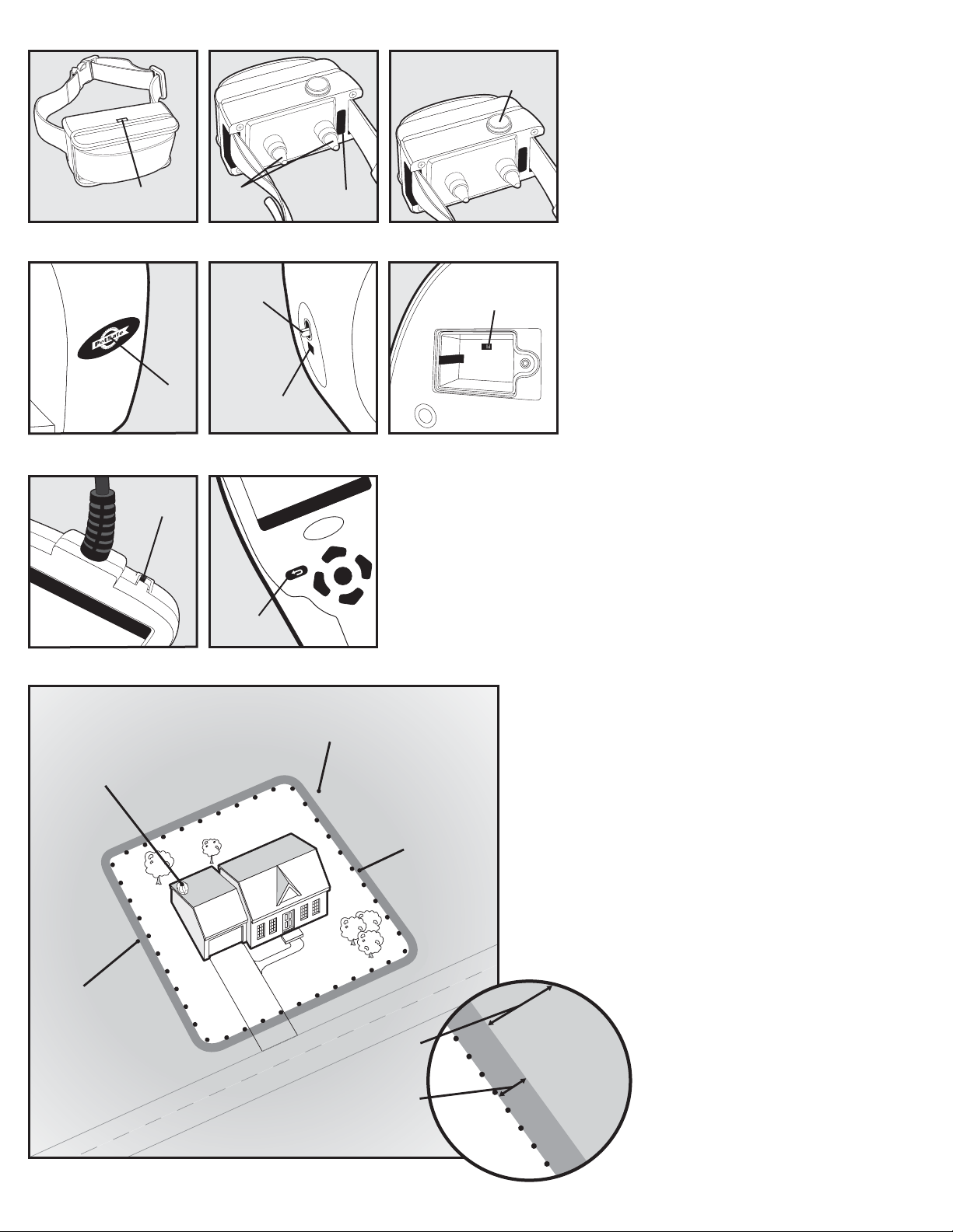
Receiver Collar
Mode
Button
Receiver
Indicator Light
Contact
Points
Charge Jack
Transmitter
Power
Switch
Power
Light
Power
Jack
Boundary Programming Unit (BPU)
Power
Switch
Back
Button
Receiver
OK
Frequency
Switch
B
A
Boundary Callouts
Fence
Transmitter
(located inside the home)
Boundary
Flags
Pet
Area
Static
Correction
Area
Correction
Warning
Static
Area
Warning
Zone
When placing your layout, keep in mind that the
Static Correction occurs approximately 1 to 5
feet beyond the Warning Zone. Make sure the
Static Correction occurs within the confines of the
Containment Area you desire and not in the street,
neighbor’s yard or dangerous area.
We recommend placing Boundary Flags AT LEAST
15 feet from dangerous areas such as the street.
Zone
Static
Correction
Area
www.petsafe.net 9
Operating Guide
Step
1
Lay out the System
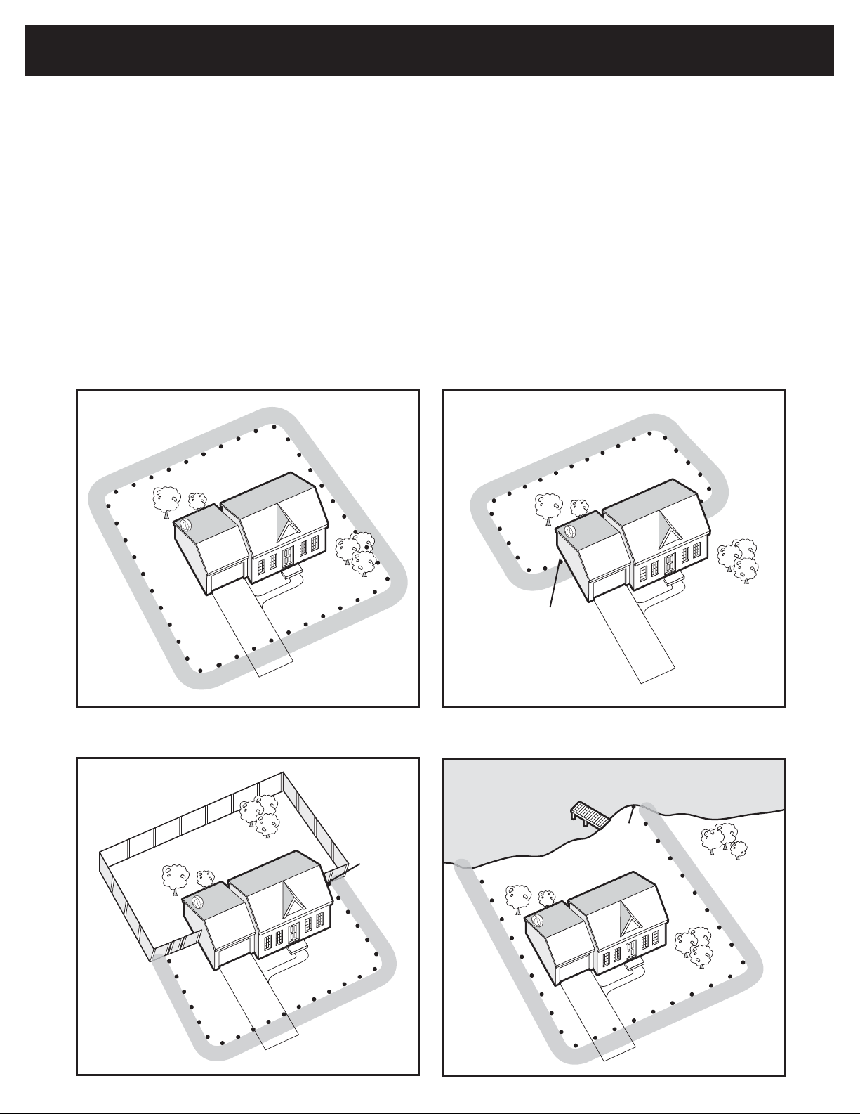
Basic Planning Tips
Design a Pet Area layout that is suitable for your yard. Create a sketch of the layout you would like to set-up in your
yard. You may want to use Google Earth to help you plan your layout. You can use a partial or full boundary.
A full boundary completely encircles the house and Fence Transmitter located within the house (
boundary requires a minimum of 40 programmed boundary flags.
A partial boundary does not completely encircle the Transmitter. Partial boundaries typically have starting and
ending flags located at house corners or up against an outside wall or fence (
requires a minimum of 10 programmed boundary flags. A partial boundary may be appropriate if:
• You want to limit the containment area to a smaller portion of the yard, such as the back yard or front yard.
• You need to avoid running your boundary parallel with buried utilities.
• Your house is so large that it cannot be completely encircled with a full boundary covering the 90 foot maximum range.
• You need to avoid violating any of the installation requirements on page 11.
The Wireless Mapping Fence can accept a maximum of 128 boundary points.
Full boundary
1A
Partial boundary: Backyard only
1B
1B, 1C, 1D). A partial boundary
1A). A full
Partial boundary: Front yard only,
using fence as boundary
1C
First
Flag
Partial boundary: Majority of yard,
using lake as boundary
1D
First
Flag
First
Flag
10 1-800-732-2677
Tip: Have all underground utilities marked before you decide which layout to pursue. In most areas this is a free
service.
1E
1F
1G
5-10 ft.
1H
Tabletop
Before setting up the Transmitter, please review and follow these requirements. You will eventually mount the
Transmitter on the wall with the supplied hardware. The Transmitter will need to be mounted as any slight
change to the Transmitter position would change the boundary. Prior to mounting the Transmitter, place and test
the Transmitter on cardboard boxes or on a non-metallic shelf. Be sure to position the Transmitter so you can
®
read the PetSafe
logo straight on and not sideways.
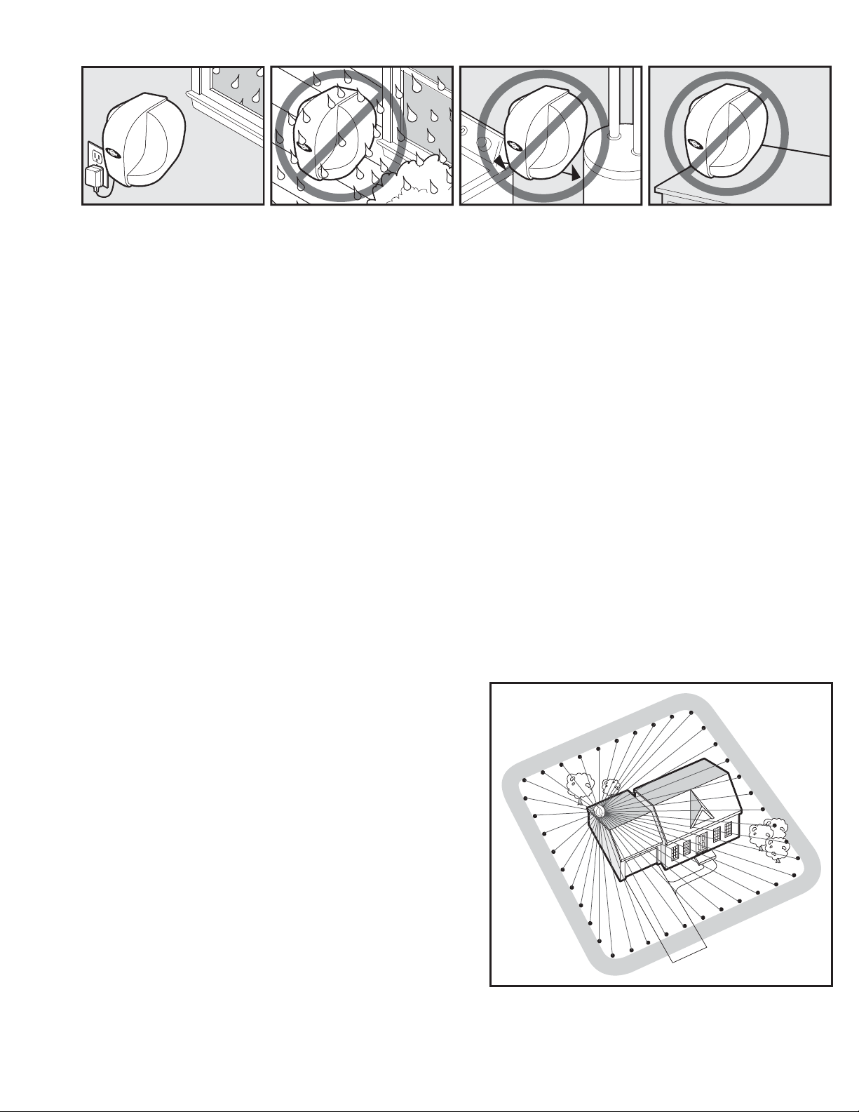
1. The Transmitter needs to be wall mounted in a dry, well-ventilated, protected area (1E).
2. Do not place the Transmitter on top of any metal surface such as a refrigerator, metal shelf, or metal table.
3. Do not mount the Transmitter within 5 feet of large metal surfaces such as refrigerators, washer/dryers,
metal tables or shelving (1G).
4. Do not locate the Transmitter closer than 10 feet from water heaters and furnaces (1G).
5. The Transmitter should not back up to a mirror on the other side of a wall. There needs to be more than 1
foot of separation between the Transmitter and the mirror.
6. Do not mount the Transmitter within 2 feet of a concrete floor or adjacent to metal HVAC ductwork.
7. If placing the Transmitter in the garage, mount Transmitter near the ceiling and at least 2 feet above roof of
any vehicle parked in the area. If the Transmitter is within 10 feet of a metal overhead garage door, it needs
to be placed above the top of the door, close to the ceiling.
8. Do not mount the Transmitter near electrical service panel or near main wiring trunks due to the large
concentration of house wiring.
9. Transmitters may be located in basements as long as installation requirements are observed.
10. For a partial boundary, locate the Transmitter at least 10 feet away from the entry door where your dog
will exit home and enter the containment area. If a successful boundary is not obtained with the first choice
Transmitter location, try a second or third location. If a trial location proves to provide a successful boundary,
then the Transmitter can be more permanently secured prior to programming a more exact final boundary.
11. Any slight movement of the Transmitter would change the boundary (1H).
When designing your layout, you also need to consider the following for this system to function properly.
Installation Requirements
• Each boundary flag placement must be located between
15 feet and 90 feet from the Fence Transmitter.
• Each boundary flag must have a unique radial line to
the Fence Transmitter and cannot cross over another
flag or block another flag (1I, 1K, 1M).
• When implementing a partial boundary, the first and
last boundary flags must be located within 1 foot of the
physical boundary, for example the house, fence, outside
wall, etc. However, keep all flags at least 3 ft from metal
doors such as storm doors or overhead garage doors.
• Any buried utility line such as power, CATV, phone or
metal water line must not run parallel (1L) with the
boundary unless separated from the boundary by at least
15 feet (1M). Because they are not buried as deeply,
CATV or phone lines usually cause more problems than
power and water lines. This may require using a partial
boundary to avoid this problem.
• Always avoid crossing buried utility lines at points far away
from the Transmitter. If it is required for the boundary to
cross a buried utility line, it should cross at approximately a right angle, and it is preferable that the crossing
be as close to the Fence Transmitter as possible, but not closer than the 15 foot minimum (1M).
• If there is a pre-existing In-Ground containment system, the perimeter wire MUST be totally
disconnected from its Fence Transmitter
1I
Each
Boundary
Flag must
have a
unique
radial line
as shown.
www.petsafe.net 11
 Loading...