

Petsafe PCF-1000-20 Operating Manual
PCF-1000-20
Deluxe In-Ground Cat Fence
Clôture anti-fugue avec fi l
de luxepour chats
Deluxe ondergronds
omheiningssysteem met
draad voor katten
Limitador de zona con cable
Operating Guide
Manuel d’utilisation
Gebruiksaanwijzing
Manual de funcionamiento
Guida all’uso
Gebrauchsanweisung
™
deluxe para gatos
Sistema antifuga con fi lo
deluxe per gatti
Deluxe unterirdisches
Rückhaltesystem mit
Draht für Katzen
ON
Si prega di leggere attentamente la guida al uso prima di utilizzare il collare
Bitte lesen Sie die gesamte Betriebsanleitung vor dem Trainingsbeginn
Please read this entire guide before beginning
Veuillez lire ce manuel en entier avant de commencer
Gelieve deze gids volledig door te lezey voordat u begint
Por favor, este manual lea completo antes de empazar

Thank you for choosing PetSafe®. Through consistent use of our products, you can have a better behaved dog in
less time than with other training tools. If you have any questions, please contact the Customer Care Centre. For a
listing of Customer Care Centre telephone numbers, visit our website at www.petsafe.net.
To get the most protection out of your warranty, please register your product within 30 days at www.petsafe.net.
By registering, and keeping your receipt, you will enjoy the product’s full warranty and should you ever need to
call the Customer Care Centre we will be able to help you faster. Most importantly, PetSafe
your valuable information to anyone. Complete warranty information is available online at www.petsafe.net.
®
will never give or sell
__________________________________________________
Table of Contents
Components ................................................................................................................................................. 3
Other Items You May Need ............................................................................................................................ 3
How the System Works .................................................................................................................................. 4
Key Defi nitions ............................................................................................................................................. 4
Operating Guide
Locate the Fence Transmitter .................................................................................................................... 5
Lay Out the System .................................................................................................................................. 5
Sample Layouts ........................................................................................................................................ 6
Position the Boundary Wire ....................................................................................................................... 7
Connect the Wires to the Fence Transmitter ............................................................................................... 8
Prepare the Receiver Collar ....................................................................................................................... 9
Function and Response Table .................................................................................................................... 9
Set the Boundary Width and Test the Receiver Collar ................................................................................10
Install the Boundary Wire .........................................................................................................................11
Place the Boundary Flags .........................................................................................................................12
Fit the Receiver Collar .............................................................................................................................13
Training Guide
Be Patient With Your Cat ..........................................................................................................................14
Preparation ..............................................................................................................................................14
Receiver Collar Familiarity .......................................................................................................................15
On-Lead Training Method .......................................................................................................................15
Supervised Tie-Out Training Method ........................................................................................................17
Accessories ..................................................................................................................................................18
Troubleshooting ...........................................................................................................................................18
Short Loop Test ...........................................................................................................................................19
To Locate a Break in the Boundary Wire .......................................................................................................19
Terms of Use and Limitation of Liability .......................................................................................................20
Battery Disposal ...........................................................................................................................................21
Compliance .................................................................................................................................................21
Caution .......................................................................................................................................................21
Français .....................................................................................................................................................22
Nederlands .................................................................................................................................................42
Español ......................................................................................................................................................62
Italiano .......................................................................................................................................................82
Deutsch .................................................................................................................................................... 102
2 www.petsafe.net
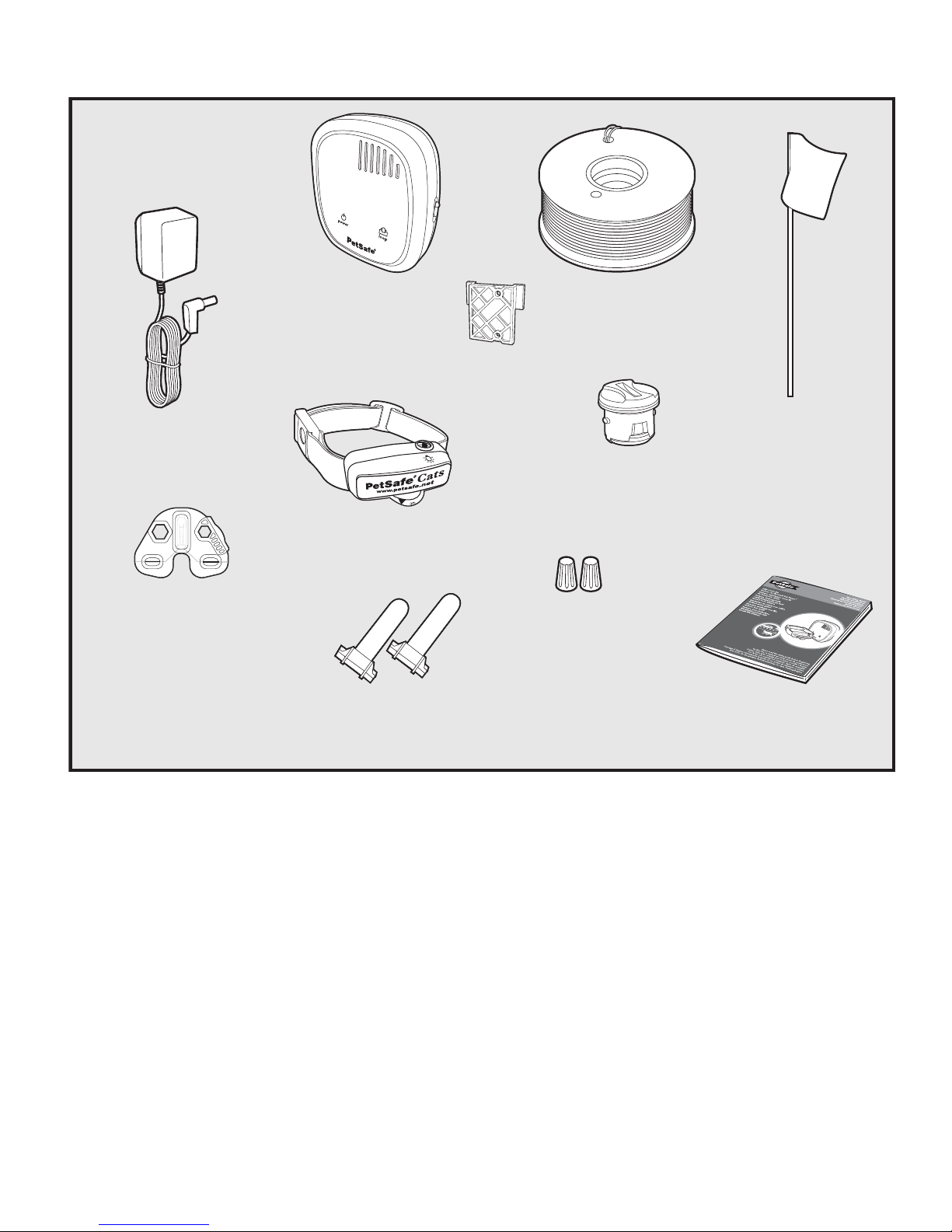
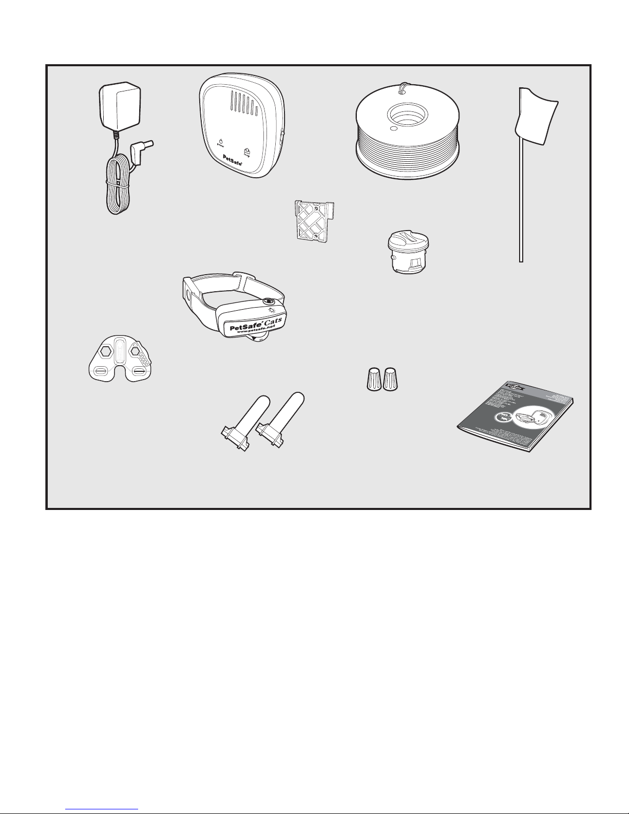
Components
Power Adapter
Test Light Tool
Fence
Transmitter
Receiver Collar
Gel-filled
Capsules
Mounting
Bracket
Boundary Wire
150 m (500 ft)
Battery
(PetSafe
Wire Nuts
®
RFA-188)
Boundary Flags - 50
Operating Guide
Other Items You May Need
• Additional wire and fl ags (Part #PRFA-500)
• Tape measure
• Small Phillips screwdriver
• Drill & mounting hardware
• Shovel or lawn edger
• Pliers
• Wire stripping pliers
• Scissors
• Lighter
• Electrical tape
• Gel-fi lled capsules
• Additional wire nuts
• Waterproofi ng compound (e.g. silicone caulk)
• PVC pipe or water hose
• Circular saw with masonry blade
• Staple gun
• Non-metallic harness and lead
Training Equipment Needed
• Harness sized to fi t your cat
• 4.6-6.1 m (15-20 ft) screw-in tie out**
**Required for supervised tie-out training. On-lead training does not require tie-out.
www.petsafe.net 3
How the System Works
The PetSafe® In-Ground Cat Fence™ has been proven safe, comfortable, and effective for cats over 2.7 kg (6 lb) and at least
6 months old. The system works by producing a radio signal from the Fence Transmitter through up to 1200 m (4000 ft) of
Boundary Wire. The Boundary Wire is buried or attached to a fi xed object to enclose the Pet Area. You temporarily defi ne
this Pet Area with Boundary Flags for a visual aid in training your cat. Your cat wears a Receiver Collar with Contact Points
that touch his neck and, once trained, is allowed to roam freely in the Pet Area. When your cat reaches the Warning Zone, the
Receiver Collar gives a warning tone. If your cat continues into the Static Correction Zone, a safe Static Correction will be
delivered through the Contact Points to get his attention until he returns to the Pet Area.
Key Definitions
Fence Transmitter: Transmits the radio signal through the Boundary Wire.
Pet Area: Area within the Warning Zone where your cat can roam freely.
Warning Zone: Outer edge of the Pet Area where your cat’s Receiver Collar begins to beep, warning him not to go into the
Static Correction Zone.
Static Correction Zone: Zone beyond the Warning Zone where your cat’s Receiver Collar will emit a Static Correction,
signaling him to return to the Pet Area.
Boundary Width: Combination of the Warning Zone and the Static Correction Zone.
Receiver Collar: Receives the radio signal from the Boundary Wire.
Receiver Indicator Light: Indicates the level of Correction at which the Receiver Collar is set. This light also serves as a
low battery indicator.
Contact Points: Deliver the safe Static Correction when your cat moves into the Static Correction Zone.
Correction Level Button: The button to adjust the level of Static Correction your cat receives in the Static Correction Zone.
Power Socket: Where the Power Adapter plugs into the Fence Transmitter. The Fence Transmitter is powered by a
standard outlet.
Boundary Control Switch: Adjust according to the length of Boundary Wire used.
Ground Terminal: The terminal where the Ground Wire connects to the Fence Transmitter.
Boundary Wire Terminals: Where the Boundary Wire connects to the Fence Transmitter in order to complete a
continuous loop.
Loop Indicator Light: Indicates that the Boundary Wire makes a complete loop, enabling the signal to be transmitted.
Boundary Width Control: Adjusts the width of the Warning and Static Correction Zones. Note: Adjusting the knob does not
change the level of Static Correction on the Collar.
Fence
Transmitter
Static Correction
Warning
Pet Area
Zone
Zone
Static Correction
Zone
Warning
Zone
Boundary
Width
4 www.petsafe.net
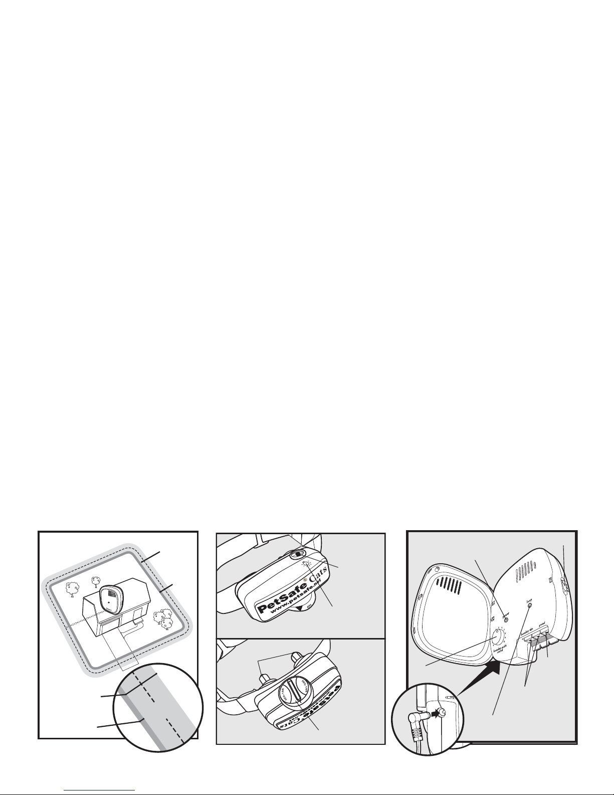
Receiver Collar
Contact
Poin ts
Correction
Level Button
Receiver
Indicator
Light
Battery Module
(Top)
(Bottom)
Fence Transmitter
Boundary Control Switch
Power Light
Boundary Width
Control
Loop Indicator Light
Power
Socket
Power
Jack
Loop Indicator Light
Boundary
Control
Ground
Switch
Terminal
Boundary Wire
}
Terminals
Boundary Wire
Terminals
Power Light
Boundary Width
Control
30 Twists/m
10 Twists/ft
Operating Guide
Step
1
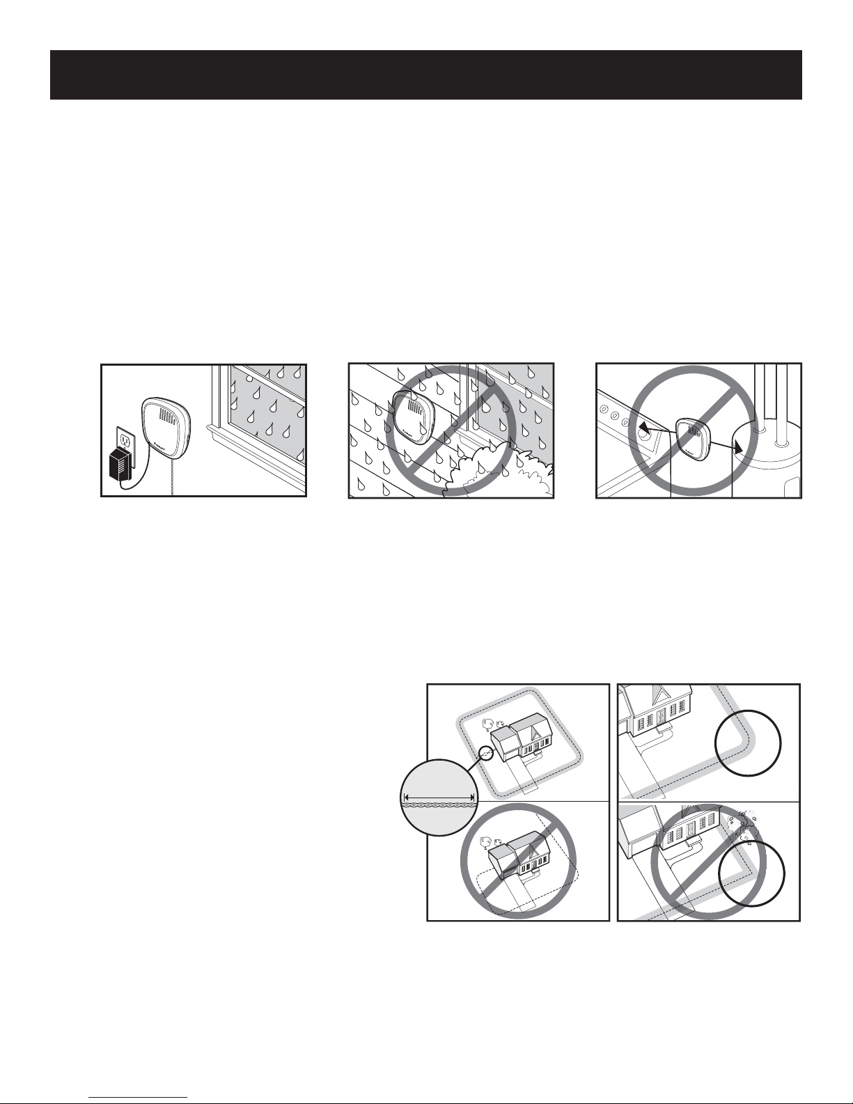
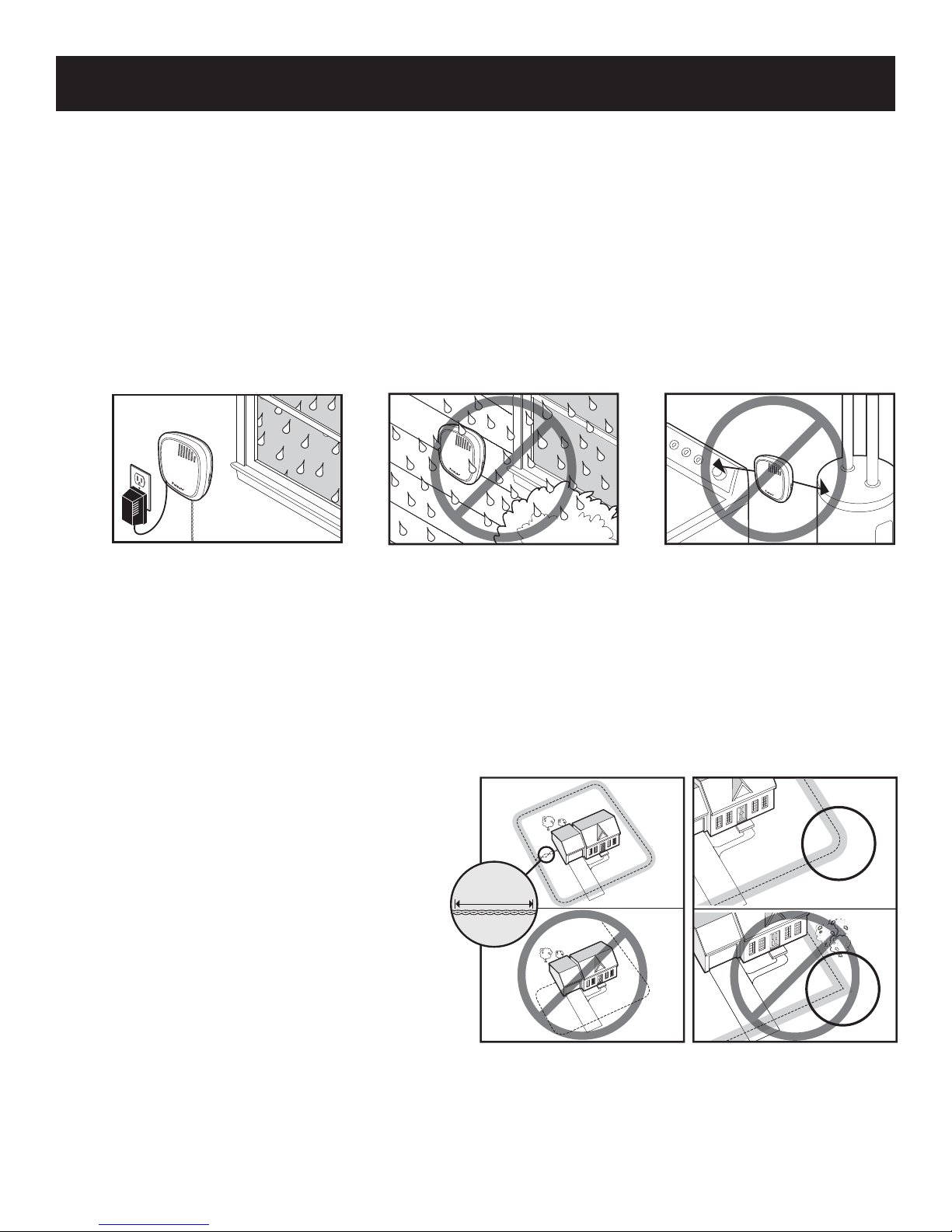
Locate the Fence Transmitter
Place the Fence Transmitter:
• In a dry, well ventilated, protected area (1A, 1B).
• In an area where temperatures do not fall below freezing (e.g., garage, basement, shed).
• Secured to a stationary surface using appropriate mounting hardware (not included). A mounting template is
included in the back of this guide.
•
At least 1 m (3 ft) from large metal objects or appliances, as these items may interfere with the signal consistency (1C).
Once you have mounted the Fence Transmitter, the Boundary Wire must exit the building. This can be
accomplished via a window or through a hole drilled through the wall. Ensure the drill path is clear of any utilities.
Make sure the Boundary Wire is not cut off or pinched by a window, door, or garage door, as this can damage it
over time.
To prevent fi res and electrical hazards, install the Fence Transmitter in buildings that are in accordance with state
and local electrical codes.
1A
1B
__________________________________________________
1C
1 m
(3 ft)
Step
Lay Out the System
Basic Planning Tips
Warning: Before digging to bury the Boundary Wire of your In-Ground Cat Fence™, make sure that there are no buried
power, telephone, or other electrical cables in the vicinity. Many underground cables carry high voltage and digging into
2
www.petsafe.net 5
them, or laying your Boundary Wire on them, may lead to hazard from shock or electrocution. Have the local utility
company mark your underground lines. In most communities this is a free service. For information regarding how these
underground wires can affect your system’s operation, see Step 3 Position the Boundary Wire.
• When planning your layout, take care to exclude
access to trees, sheds or other items your cat
can use to jump over the Boundary. The signal
from the Boundary Wire only extends the same
distance vertically as horizontally. If your cat
can take the Receiver Collar out of reach of
the signal, he can jump the Boundary without
receiving a Static Correction.
•
The Boundary Wire MUST start at the Fence
Transmitter and make a continuous loop back (2A).
• Twisting the Boundary Wire cancels the signal
and allows your cat to cross over that area safely.
Plastic or metal piping will not cancel the signal.
Twist the Boundary Wire 30 times per meter (10
times per foot) to cancel the signal
• Design a layout that is suitable for your garden.
Sample layouts are provided in this section, and a grid for designing your layout is provided in the back of this guide.
• Always use gradual turns at the corners with a minimum of 1 m (3 ft) radius to produce a more consistent
boundary (2B). Do not use sharp turns, as this will cause gaps in your boundary.
• Avoid making passageways too narrow for your cat to move about freely (e.g., along the sides of a house).
• The Receiver Collar can be activated inside the house if the Boundary Wire runs along the outside wall of the
house. If this occurs, remove your cat’s Receiver Collar before bringing him inside, decrease the range using the
Boundary Width Control, or consider an alternative layout.
(2A)
.
2A
2B
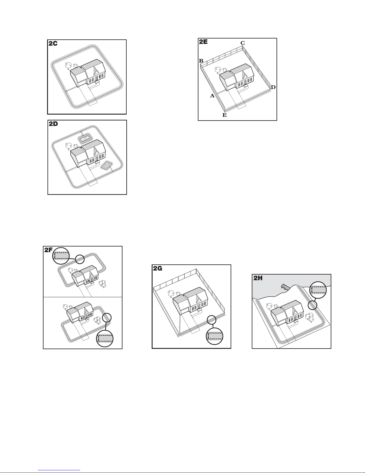
Sample Layouts
Sample 1:
Perimeter Loop
(Single Loop)
The Perimeter
Loop is the
most common
layout. This will
allow your cat to
freely and safely
roam your entire
property (2C). It
can also protect
gardens and
landscaping (2D).
Sample 2 (2E): Perimeter Loop Using Existing
Fence (Single Loop)
This layout allows you to include your existing fence as
part of your layout and keep your cat from jumping out or
digging under your existing fence. It reduces the amount
of wire which will need to be buried. From the Fence
Transmitter, run the wire to A, A to B, B to C, C to D,
D to E, E to A, twist the wires from A back to the Fence
Transmitter. See the “Install the Boundary Wire” section
for more information on attaching the wire to a fence.
Double Loop
A Double Loop must be used when you are not establishing the Boundary Zone on all sides of your property.
When using a Double Loop, the Boundary Wire must be separated by a minimum of 1 TO 1.5 METERS
(3 TO 5 FEET) to avoid canceling the signal. Remember that a Double Loop will require twice as much wire.
D
E
F
E
F
D
1-1.5 m
(3-5 ft)
C
1-1.5 m
(3-5 ft)
B
A
B
A
C
Sample 3 (2F): Front or Back
Yard Only (Double Loop)
From the Fence Transmitter, run
the wire to A, A to B, B to C, C
to D, D to E, E to F, make a
U-turn and follow your path all
the way back to A, keeping the
wire separated 1 to 1.5 meters
(3 to 5 feet). Twist the wire from
A back to the Fence Transmitter.
A
1-1.5 m
(3-5 ft)
Sample 4 (2G):
Front Boundary Only
(Double Loop)
From the Fence Transmitter,
run the wire to A, A to B, B
back to A keeping the wire
separated 1 to 1.5 meters
(3 to 5 feet). Twist the wire
from A back to the Fence
Transmitter.
E
B
B
A
C
1-1.5 m
(3-5 ft)
D
Sample 5 (2H): Lake Access
(Double Loop)
From the Fence Transmitter,
run the wire to A, A to B,
make a U-turn and go to C, C
to D, D to E, make a U-turn
and follow your path all the
way back to A keeping wire
separated 1 to 1.5 meters
(3 to 5 feet). Twist the wire
from A back to the Fence
Transmitter.
6 www.petsafe.net
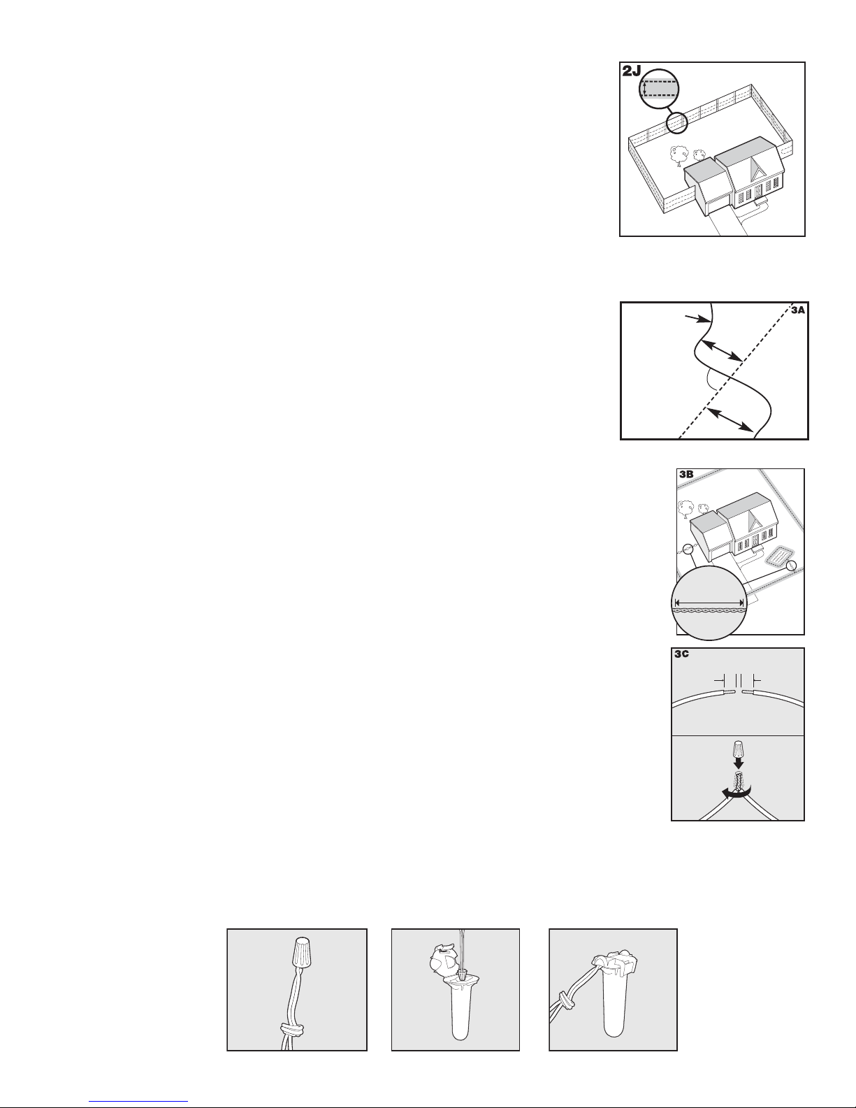
Sample 6 (2J): Wire Loop Attached to Existing Fence (Double Loop)
30 Twists/m
10 Twists/ft
This layout allows you to include your existing fence as part of your layout and
keep your cat from jumping out or digging under your existing fence. It reduces
the amount of wire which will need to be buried. Run the wire from the Fence
Transmitter to A, A to B, B to C, C to D, D to E, E to F, make a U-turn and
follow your path all the way back to A,
(3-5 ft). Twist the wire from A back to the Fence Transmitter. See the “Install the
Boundary Wire” section for more information on attaching the wire to a fence.
keeping the wire separated 1-1.5 m
1-1.5 m
(3-5 ft)
C
A
B
D
F
__________________________________________________
E
Step
3
Position the Boundary Wire
Lay out the Boundary Wire using your planned boundary and test the
system BEFORE burying the wire or attaching it to an existing fence.
This will make any layout changes easier.
insulation can diminish the signal strength and create a weak area where your pet
can escape.
Running the Boundary Wire parallel to and within 1.5 m (5 ft) of electrical wires,
neighboring containment systems, telephone wires, television or antenna cables, or
satellite dishes may cause an inconsistent signal. If you must cross any of these, do
so at 90-degree angles (perpendicularly) (3A).
If separating the Boundary Wire by at least 3 m (10 ft) from a neighboring containment
system’s wire does not reduce the inconsistent signal, contact the Customer Care Centre.
Work carefully. A nick in the wire
To Twist the Boundary Wire
Twisting the Boundary Wire cancels the signal and allows your pet to cross over that area safely
(3B). To ensure the signal is cancelled, it is recommended that you cut and splice the Boundary
Wire between each twisted section. Plastic or metal piping will not cancel the signal. You can
twist your own wire by cutting two equal lengths of Boundary Wire supplied and twisting them
together. Anchor one end of the wires to something secure and insert the other end in a power
drill. Pull the wire taut. The drill enables you to twist the wire quickly. Twist the Boundary Wire
30 times per metre (10 to 12 times per ft) to cancel the signal. Once you have completed your
boundary layout, insert the twisted wire and insert into the transmitter.
To Splice or Repair the Boundary Wire
If you need additional Boundary Wire to expand your wire loop, you will need to splice the
wires together. Note the locations of all splices for future reference. Most Boundary Wire breaks
occur at splices.
Strip approximately 1 cm (
(3C). Make sure the copper Boundary Wire is not corroded. If the Boundary Wire is corroded,
cut it back to expose clean copper wire.
Insert the stripped ends into the wire nut and twist the wire nut around the wires. Ensure that
there is no copper exposed beyond the end of the wire nut. Tie a knot 7.5-10 cm (3-4 in) from
the wire nut (3D). Ensure that the wire nut is secure on the wire splice.
Once you have securely spliced the wires together, open the lid of the gel-fi lled splice capsule and insert the wire nut
as deeply as possible into the waterproof gel inside the capsule (3E). Snap the lid of the capsule shut (3F). For proper
system performance, the splice connection must be waterproof.
If your splice pulls loose, the entire system will fail. Make sure your splice is secure. Additional gel-fi lled splice capsules
and wire nuts are available through the Customer Care Centre.
3
/8 in) of insulation off the ends of the Boundary Wires to be spliced
3D
3E
3F
Boundary Wire
90˚
1 cm
3
(
/8 in)
3 m
10 ft
3 m
10 ft
2
Buried Cabl
(
1
1 cm
3
/8 in)
e
www.petsafe.net 7
Step
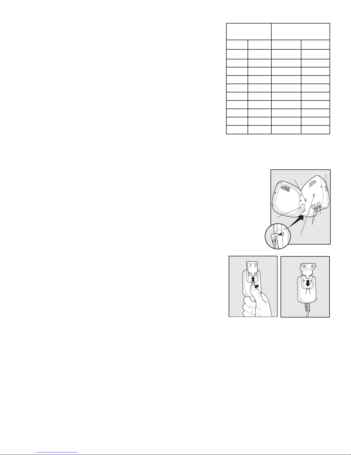
Additional Boundary Wire
Extra direct burial Boundary Wire can be purchased in 150 m (500 ft)
spools at the store where you purchased the kit or through the Customer
Care Centre.
Note: When adding Boundary Wire, it must act as a continuous loop.
The table at right indicates the approximate length of Boundary Wire
needed for a square, Single Loop layout. Length will vary due to the
amount of twisted wire and layout used. Remember that a Double
Loop will require twice as much wire.
Area to be
enclosed
Ares Acres Metres Feet
10 1/4 127 415
13 1/3 146 480
20 1/2 180 590
40 1 255 835
80 2 360 1180
200 5 570 1870
400 10 800 2600
600 15 1000 3200
800 20 1100 3700
900 22 1200 4000
Approximate wire
length required
__________________________________________________
Connect the Wires to the Fence Transmitter
4
Boundary Wire
1. Run the Boundary Wire to the Fence Transmitter through a window, under a door,
through a crawl space vent, or any other appropriate available access. You can also
drill a hole through your wall.
2. Strip the ends of the Boundary Wire approximately 1.3 cm (1/2").
3. Insert the Boundary Wires into the Boundary Wire Terminals on the Fence
Transmitter. Make sure wires do not touch each other at the terminals.
4. Turn the Boundary Width Control knob to 10. This will set the Warning Zone at the
maximum width.
5. Plug the Power Adapter into the Power Socket and a working outlet. The Power
Adapter comes with the North American plug installed and additional plugs for the
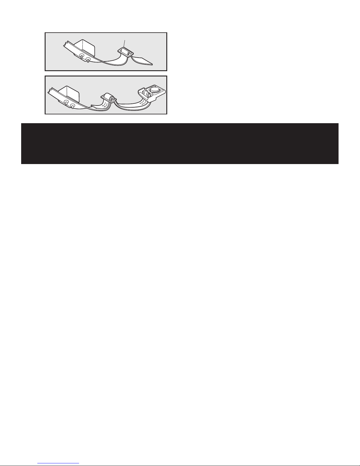
UK and Europe. To change the plug:
a. Push in the tab on the Power Adapter and remove the plug by
sliding it off as shown (4B).
b. Slide the proper plug for your electrical outlet onto the Power
Adapter as shown (4C).
6. The Power Light and Loop Indicator Lights should come on. If this
does not happen, see the “Troubleshooting” section.
(4A)
4B 4C
4A
Power Light
Boundary Width
Control
Power
Socket
Boundary Control Switch
Ground
Terminal
Boundary Wire
Terminals
Loop Indicator Light
8 www.petsafe.net
Ground Wire
Proper grounding, although not necessary for the system to work, will help reduce the
chance of electrical surges causing damage to your Fence Transmitter and/or Power
Adapter. To ground your unit, you will need a solid (not stranded) Ground Wire (14 to
18 gauge insulated copper wire) and a ground rod with clamp, which may be obtained
at most electrical supply stores. Connect one end of the Ground Wire to the Ground
Terminal located on the Fence Transmitter and the other end of the Ground Wire to
the ground rod. The ground rod must be buried at least three feet into the ground and
located as close as possible to the Fence Transmitter.
(4D)
4D
Ground
Wire
Step
5
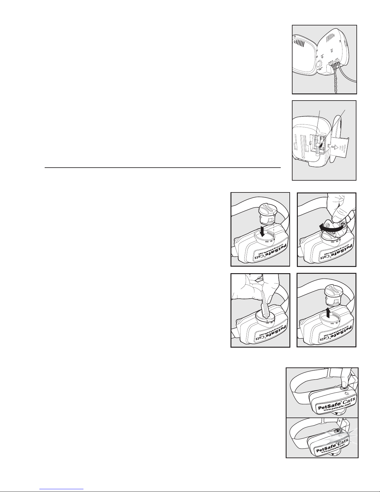
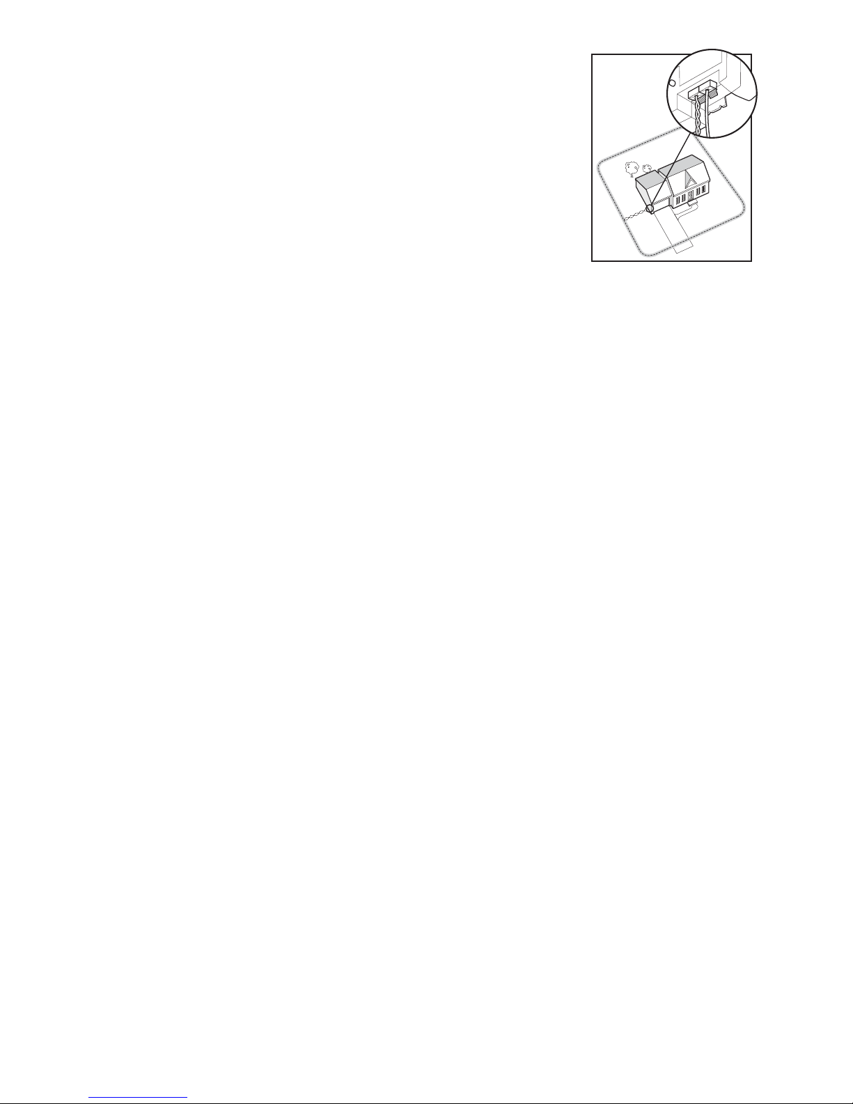
Fuse Protection
The Fence Transmitter is also equipped with a 250 volt, ½ amp fuse to protect the unit’s
electronic circuitry from electrical power surges. To locate the fuse, slide off the lid on
the back of the Fence Transmitter. A spare fuse is also provided.
(4E)
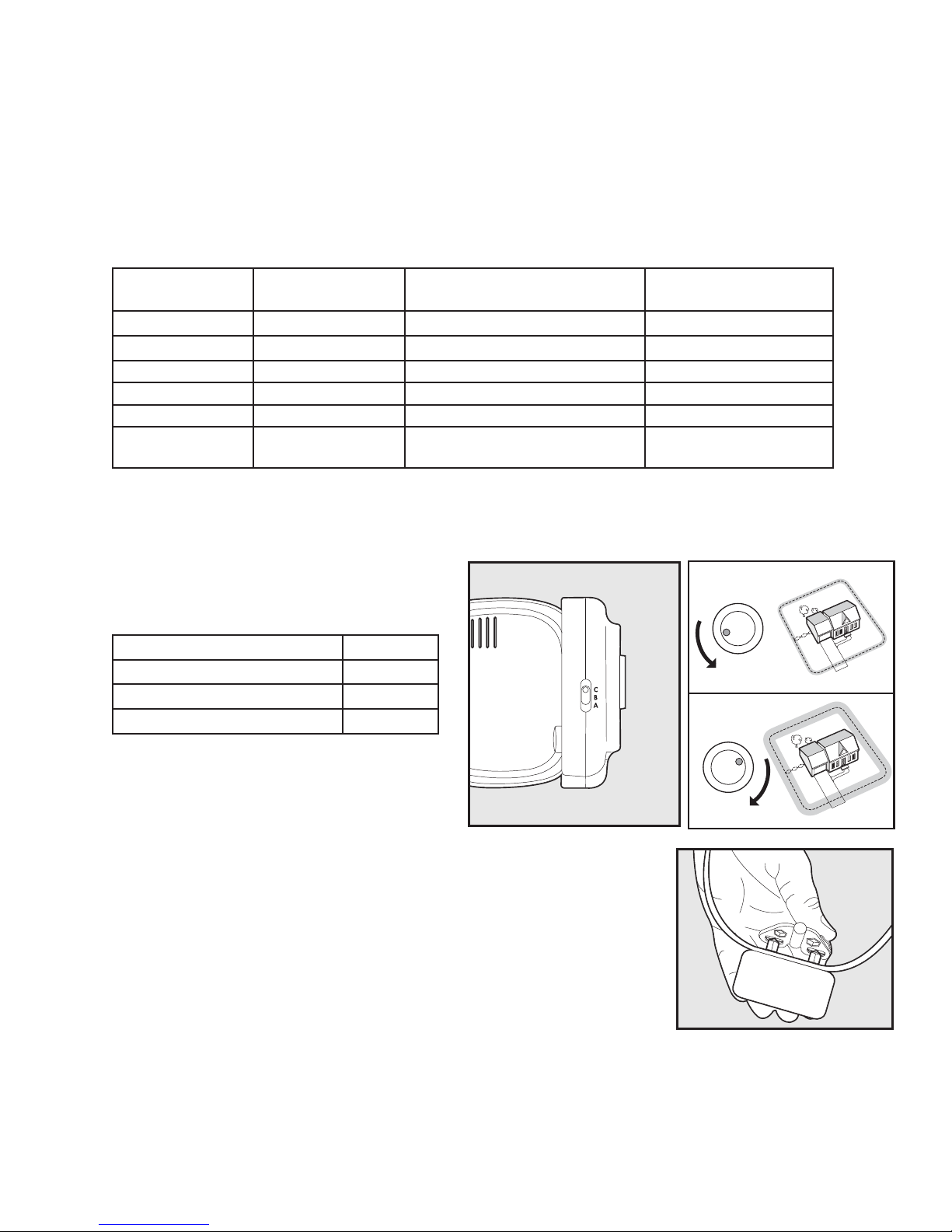
Prepare the Receiver Collar
To Insert and Remove the Battery
Note: Do not install the battery while the Receiver Collar is on your pet.
This Receiver Collar utilizes a replaceable PetSafe® battery
(RFA-188). This unique battery is designed to make battery
replacement easier and increase water protection.
To activate the collar, insert the battery module (5A). Using the edge
of the Test Light Tool as shown, turn the battery clockwise until the
vertical line on the battery is pointed to the “ON” position (5B).
If the PetSafe® Receiver Collar is not going to be used on the cat
immediately, leave it in the “OFF” position.
To remove the battery, turn the battery counter-clockwise using
the edge of the Test Light Tool as shown (5C, 5D). DO NOT
attempt to cut into or pry open the battery. Be sure to discard the
used battery properly.
A replacement PetSafe
our website at www.petsafe.net for a listing of Customer Care Center
telephone numbers or for a listing of common retailers.
®
battery can be found at many retailers. Visit
5A 5B
5C
4E
FuseSpare Fuse
5D
Two Colour LED
The two colour LED indicator shows good or low battery. Good battery equals 1 fl ash every 60 seconds with Green LED.
Low battery equals 3 fl ashes every 60 seconds with the Red LED. If there are no LED lights it is time to change the battery.
To Set the Static Correction Level
Read all steps before attempting to set the Static Correction Level.
1. With the battery installed, press the Correction Level Button and release when the
Receiver Indicator Light lights red (5E).
2. The Receiver Indicator Light will emit a number of red fl ashes representing the Static
Correction Level (5F).
3. Increase the Static Correction Level by pressing and releasing the Correction Level
Button within 5 seconds of the previous fl ashes.
The Static Correction Levels increase from 1 to 5. Pushing the Correction Level Button
while the Receiver Collar is on level 5 will cause the Receiver Collar to revert to level 1.
Refer to the Function and Response Table to choose the Static Correction level that best
fi ts your pet.
www.petsafe.net 9
5E
5F
The Receiver Collar is equipped to automatically increase the level of Static Correction the longer your pet remains
in the Static Correction Zone, if the collar is set at level 2 or above.
The Receiver Indicator Light acts as a low battery indicator, fl ashing every 60 seconds when battery replacement is required.
Over Correction Protection
In the unlikely event that your cat “freezes” in the Static Correction Zone, this feature limits the static correction duration
to 30 seconds. The system locks out further static correction until the pet leaves the Static Correction Zone.
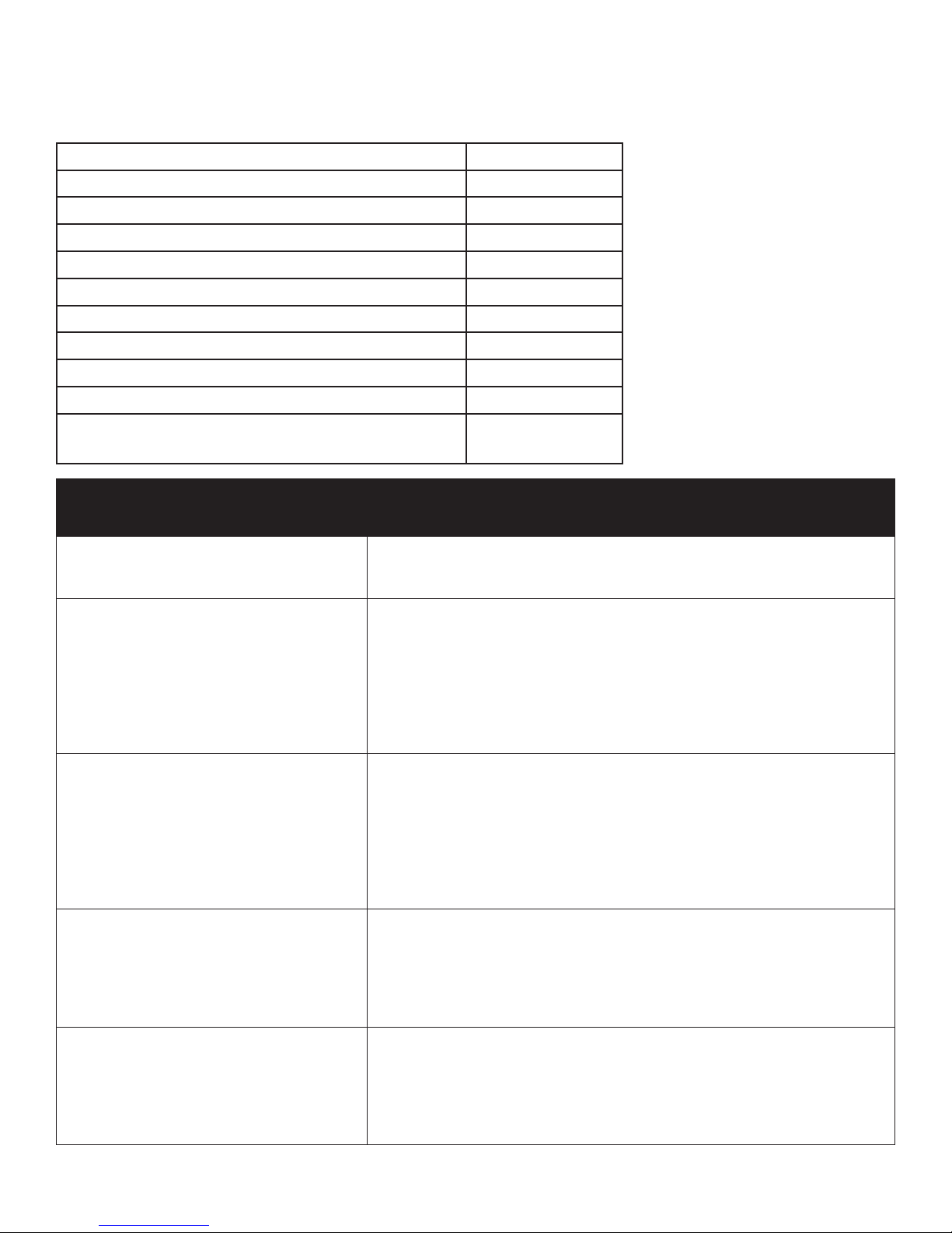
Function and Response Table
Note: Begin training with Correction Level 2 and only increase if your cat does not respond to the Static Correction.
Step
6
Indicator Light
Response
1 Flash 1 No Static Correction, Beep Only
2 Flashes 2 Low Static Correction Timid
3 Flashes 3 Medium Static Correction Timid or Average
4 Flashes 4 Medium-High Static Correction Average or High Energy
5 Flashes 5 High Static Correction High Energy
Flashes once every
4 to 5 seconds
____________________________________________________________________________________________________
Static Correction
Level
Low Battery
Receiver Collar Function Temperament of cat
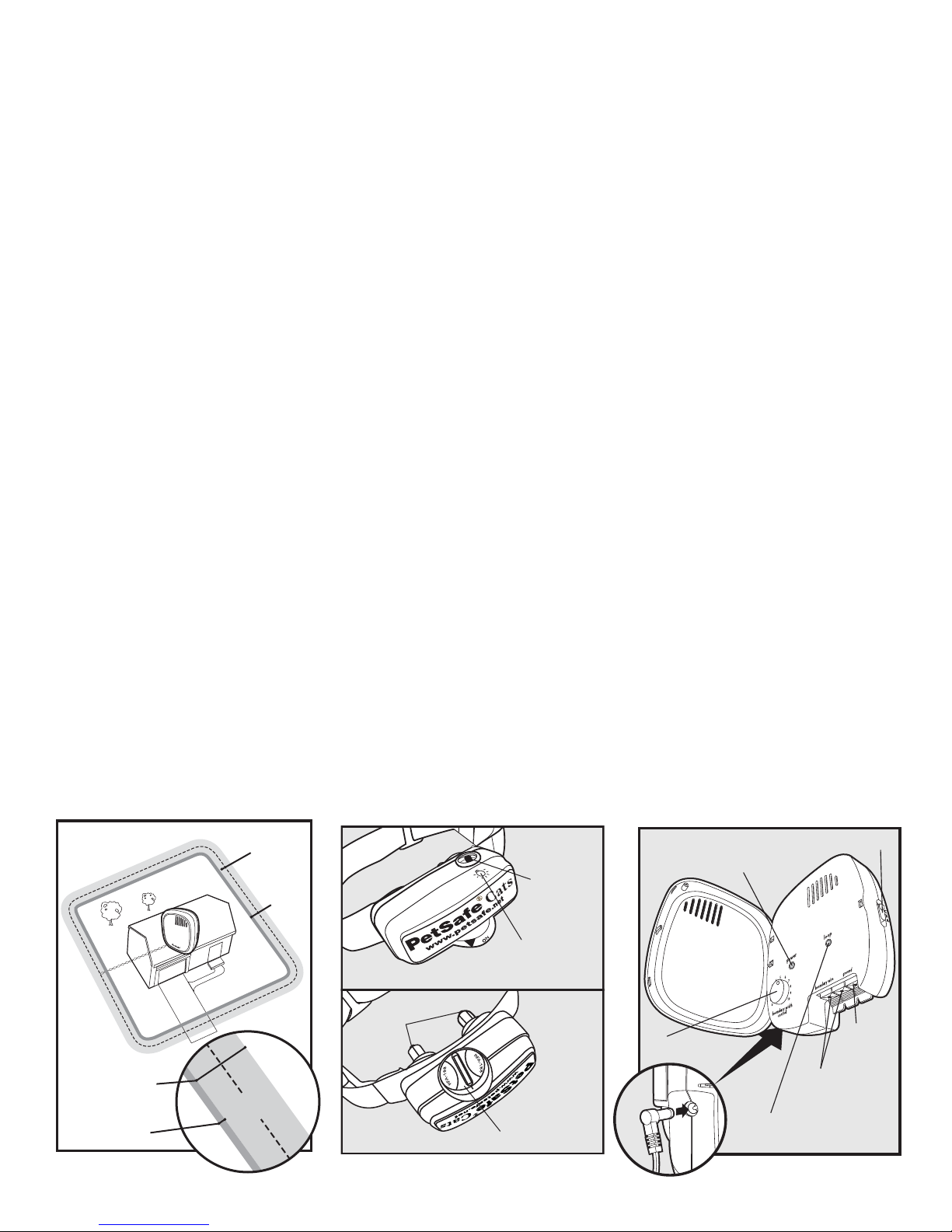
Set the Boundary Width and Test the Receiver Collar
The Boundary Control Switch on the side of the
Fence Transmitter has three settings (6A). Setting B
is used for most properties. The following table will
indicate the setting you should use.
Amount of Wire Setting
Up to 400 m (1300 ft)
400-730 m (1300-2400 ft)
Greater than 730 m (2400 ft)
Use the Boundary Width Control knob to set the
width of the Warning Zone and Static Correction
Zone (6B). Set the Boundary Width as wide as
possible to give your cat the widest Warning and
Static Correction Zones without reducing the
Pet Area too much. We recommend a 3.7-6 m
(12-20 ft) Boundary Width.
Note: The Boundary Width Control knob does not change the Static Correction Level.
To identify the Warning and Static Correction Zones, make sure the Receiver Collar
battery is properly installed, the Static Correction Level is set at 2 or above, and the
Test Light contacts are held to the Contact Points (6C). For best results, select a
section of straight Boundary Wire that is at least 15 m (50 ft) long. Hold the Test
Light tool contacts to the Contact Points (6C). Walk toward the Boundary Wire with
Contact Points pointing up and holding the Receiver Collar at your pet’s neck level
(6D) until the Receiver Collar beeps (6E) and the Test Light Tool fl ashes.
Note: The Receiver Collar is waterproof, which can make the beep hard to hear.
If the Receiver Collar does not beep at the desired range, adjust the Boundary
Width Control knob to the desired setting. Turning the Boundary
B
C
A
6B6A
5
6
4
3
28
1
4
3
28
1
0
7
9
10
0
5
6
7
9
10
6C
10 www.petsafe.net
Width Control knob clockwise increases
the Boundary Width while turning it
counterclockwise decreases it (6B). Repeat
this activity as needed until the Receiver
Collar beeps at the desired distance from the
Boundary Wire.
The numbers on the Boundary Width Control
knob indicate signal strength and are not
representative of Boundary Width footage. If
adjusting the Boundary Width Control knob
does not give the desired range, adjust the Boundary Control Switch to another setting to achieve your desired range. If
using a Double Loop, you may need to increase the separation of the Boundary Wire to achieve desired range.
The Receiver Collar beeps as a warning tone and ticks when delivering a Static Correction. After hearing the beep,
continue to walk towards the wire. The Receiver Collar should tick and the Test Light should fl ash, indicating the
Static Correction as you enter the Static Correction Zone (6F). A warning tone and the fl ashing of the Test Light
indicate that the Receiver Collar and the system are working properly. Test in a number of different areas until you
are satisfi ed that the system is functioning properly. Next, walk all around the Pet Area to ensure there are no areas
where the Receiver Collar may activate from signals coupled onto buried wires or cables. Test the collar in and
around the inside of the house as well. As mentioned, cable and wires from cable TV, electrical or telephone lines
may conduct pet fencing signals inside and outside the house that can activate the cat’s collar accidentally. While
rare, if this occurs your Boundary Wire is probably too close to these outside lines and should be moved or modifi ed
as shown in Figure 3A.
If you are satisfi ed that your system is functioning properly, you are ready to start burying the Boundary Wire. If the
Receiver Collar did not beep or the Test Light did not fl ash, see the “Troubleshooting” section.
Note: The Boundary Width is broken down into 20% War ning Zone and 80% Static Correction Zone.
6D 6E 6F
Boundary
Wire
Boundary
Wire
Step
7
____________________________________________________________________________________________________
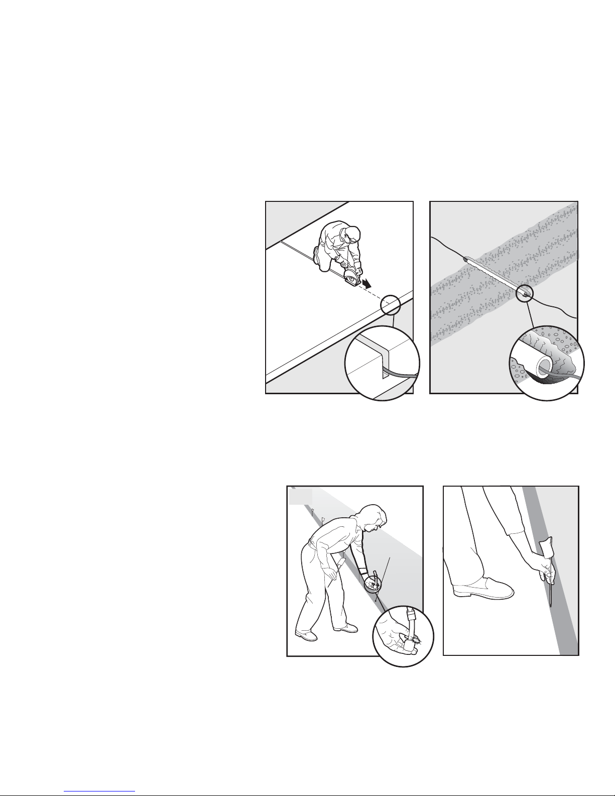
Install the Boundary Wire
To Bury the Boundary Wire
Burying the Boundary Wire is recommended to protect it and prevent disabling the system.
1. Cut a trench 2.5-7.5 cm (1-3 in.) deep along your planned boundary.
2. Place the Boundary Wire into the trench maintaining some slack to allow it to expand and contract with
temperature variations.
3. Use a blunt tool such as a wooden paint stick to push the Boundary Wire into the trench. Be careful not to
damage the Boundary Wire insulation.
To Attach the Boundary
Wire to an Existing
Fence
The Boundary Wire of the PetSafe® InGround Cat Fence™ can be attached
to a chain link fence, split rail fence,
or a wooden privacy fence. The
Boundary Wire can be attached as high
as needed. However, make sure the
Boundary Width is set at a high enough
range for your cat to receive the
signal. If using a Double Loop with an
existing fence at least 1m (3 ft) tall, run
the Boundary Wire on top of the fence
and return it on the bottom of the
fence to get the 1 to 1.5 m (3 to 5 ft)
separation needed.
7A
WEAVE WIRE INTO FENCE
STAPLE WIRE TO FENCE
STAPLE WIRE
TO FENCE
7B
SINGLE LOOP
1-1.5 m
(3-5 ft)
DOUBLE LOOP
1-1.5 m
(3-5 ft)
www.petsafe.net 11
• Chain Link Fence (7A): Weave Boundary Wire through the links or use plastic quick ties.
• Wooden Split Rail or Privacy Fence (7A): Use staples to attach Boundary Wire. Avoid puncturing the
insulation of the Boundary Wire.
• Double Loop with an Existing Fence: Run the Boundary Wire on top of the fence and return it on the bottom
of the fence to get the 1 to 1.5 m (3 to 5 ft) separation needed.
• Gate (Single Loop) (7B): Bury the Boundary Wire in the ground across the gate opening. Note: The signal is still
active across gateway when the gate is open, so your cat is still deterred from leaving the Pet Area.
• Gate (Double Loop) (7B): Bury both Boundary Wires across the gate opening while keeping them 1 to 1.5 m
(3 to 5 ft) apart.
To Cross Hard Surfaces (driveways, sidewalks, etc.)
• Concrete Driveway or Sidewalk
(7C): Place the Boundary Wire in a
convenient expansion joint or create
a groove using a circular saw and
masonry blade. Place the Boundary
Wire in the groove and cover with an
appropriate waterproofi ng compound.
For best results, brush away dirt or
other debris before patching.
• Gravel or Dirt Driveway (7D): Place
the Boundary Wire in a PVC pipe or
water hose to protect the Boundary
Wire before burying.
7C
7D
Step
8
__________________________________________________
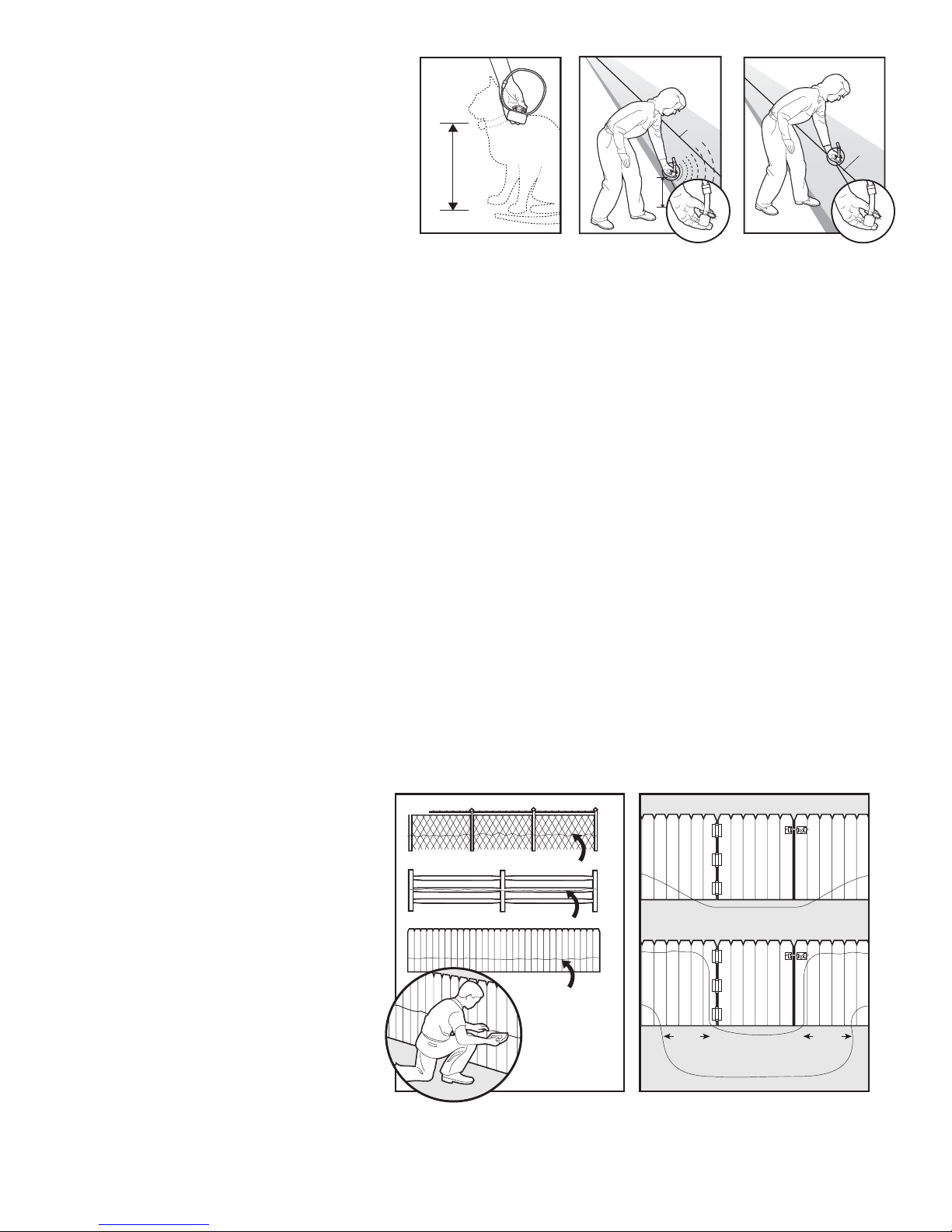
Place the Boundary Flags
The Boundary Flags are visual reminders for your cat of where the Warning Zone is located.
1. Hold the Receiver Collar at your cat’s
neck height.
2. Walk towards the Warning Zone until the
Receiver Collar beeps (8A).
3. Place a Boundary Flag in the ground (8B).
4. Walk back into the Pet Area until the
beeping stops.
5. Repeat this process around the Warning
Zone until it is marked with Boundary
Flags every 3 m (10 ft) or less.
Note: If you cannot hear the beep, see the Test
Light Instructions in Step 6.
8A
Boundary
Wire
8B
12 www.petsafe.net
Step
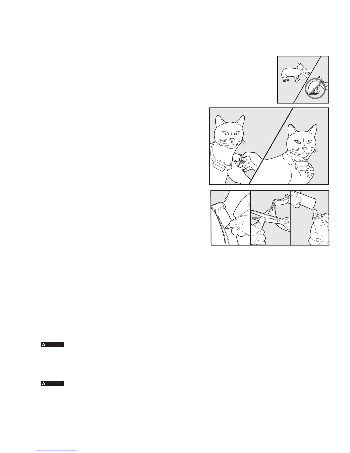
Fit the Receiver Collar
Important: The proper fit and placement of your Receiver Collar is important for effective training. The
Contact Points must have direct contact with your cat’s skin on the underside of his neck.
9
To assure a proper fit, please follow these steps:
1. Make sure that the batteries are not installed in the Receiver Collar.
2. Start with your cat standing comfortably (9A).
3. Centre the Contact Points underneath your cat’s neck, touching the skin. Note: It is
sometimes necessary to trim the hair around the Contact Points to make sure that contact
is consistent.
4. Check the tightness of the Receiver Collar by inserting one
finger between the end of a Contact Point and your cat’s
neck. The fit should be snug but not constricting (9B).
5. Allow your cat to wear the collar for several minutes then
recheck the fit. Check the fit again as your cat becomes
more comfortable with the Receiver Collar.
6. Trim the collar as follows (9C):
a. Mark the desired length of the Receiver Collar with a
pen. Allow for growth if your cat is young or grows a
thick winter coat.
b. Remove the Receiver Collar from your cat and cut off
the excess.
c. Before placing the Receiver Collar back onto your cat, seal
the edge of the cut collar by applying a flame along the
frayed edge.
9B
9C
9A
Important: For comfort, safety and effectiveness of product, please ensure the following:
• During the fi rst 2 weeks of training, do not use the training device on your pet without
direct supervision.
• Check the fi t to prevent excessive pressure by being able to insert one fi nger between the Contact Point
and your pet’s skin.
• Never leave the Receiver Collar on your pet for more than 12 consecutive hours.
• Your pet must be carefully examined daily for any signs of a rash or sore.
• If a rash or sore is observed, discontinue the use of the Receiver Collar for a few days.
• If the condition persists beyond 48 hours, see your veterinarian.
• Your pet’s neck and the Contact Points must be washed weekly with a wash cloth and mild hand soap,
then rinsed thoroughly.
CAUTION
prolonged contact against the contact points, may occur if the steps above are not followed.
The system should only be used with pets who are over 6 months of age. If your pet is injured or its
mobility is otherwise impaired, contact your veterinarian or professional trainer before use.
CAUTION
against your pet’s neck. Attach a lead to a separate, non-metallic collar or harness, making sure the
extra collar does not put pressure on the Contact Points.
A condition called Pressure Necrosis, which is a devitalization of the skin due to excessive and
Do not attach a lead to the collar. This can result in pulling the Contact Points too tightly
www.petsafe.net 13
To Re-Thread the Collar
Slide Buckle
The slide buckle prevents the collar from becoming loose
around your cat’s neck.
Training Guide
Cat Training Introduction
This training guide offers a choice of two training methods: On Lead Method and Supervised Tie Out
Method. Both methods require close supervision of your cat throughout the training period. Carefully
read both methods to determine which is right for you and your cat.
Be Patient With Your Cat
Important: Proper training of your cat is essential to the success of the PetSafe® In-Ground Cat
Fence™. Read this section completely before beginning to train your cat. Remember that the PetSafe®
In-Ground Cat Fence™ is not a solid barrier.
• Training should be fair, firm and consistent.
• Train for 10 to 15 minutes at a time. Don’t try to do too much too quickly. More-frequent short sessions are better
than less-frequent longer sessions.
• If your cat shows signs of stress, slow down the training schedule and/or add additional days of training.
• Finish each training session with lots of praise and affection.
• Remove the Receiver Collar after each training session.
• Keep your cat on a harness attached to a lead during training sessions.
• Even if you think your cat is responding well to the training, complete the entire training.
Reinforcement is important.
• Regularly check the fit of the Receiver Collar against your cat’s skin.
__________________________________________________
Preparation
Your goal is to train your cat to turn away from the Boundary Zone every time he hears the warning beep from the
Receiver Collar.
During training, your cat must develop an understanding of the Boundary and that you require him to remain within it.
Cats are independent creatures. In order to gain the correct response, you must always work with a kind, calm and
respectful manner. Gain your cat’s trust and you will build a mutual respect which will ultimately lead to success.
It must be remembered that by their very nature cats are more agile and therefore more mobile than dogs. You
must be very aware of your training environment. If it is possible for your cat to climb on a shed or up a tree, taking
the Receiver Collar out of reach of the signal from the Boundary Wire, then it is possible that he could jump the
Boundary without receiving a Static Correction.
The time scale for fully training your cat can range from one to two weeks. During the training period, you should
be able to detect from your cat’s response if it is time to move on to the next training phase.
14 www.petsafe.net

Receiver Collar Familiarity
Goal:
To familiarize your cat with the Receiver Collar if he has not worn one before.
Steps:
1. Fit the Receiver Collar as detailed in Step 9 of this guide, but without batteries inserted, so there is no chance of
your cat receiving a correction at this early stage.
2. Reward your cat for allowing you to put on the Receiver Collar and leave him for a short period of time (5 - 15
minutes). Gradually increase the time your cat spends wearing the Receiver Collar to an hour or more.
3. Your cat is ready to move on to Phase 1 when you observe him behaving normally (e.g., grooming, eating,
sleeping, showing affection) while wearing the Receiver Collar.
Training Guide
On-Lead Method
Phase
1
Days 1 thru 2 – Boundary Awareness - Warning Zone
Perform three or four training sessions per day, each lasting 10 – 15 minutes.
Important:
• Your cat MUST stay in a harness for training, to allow for any unpredictable response. The harness also
gives you control to guide your cat to a “place of safety” within the Pet Area once warned or corrected
by the Receiver Collar.
• If your cat attempts to leave the Pet Area, make sure he does not get past the Boundary Flags. Never
let the cat past the Boundary Flags with or without the Receiver Collar on. If your cat thinks he can
pass the Boundary Flags, training will take longer.
Goal:
To teach your cat to associate the beep with the position of the Warning Zone.
Steps:
1. Set the Receiver Collar to Level 1 (Tone Only).
2. Put the harness and lead on your cat. Lead him into the Pet Area and up to a chosen point by the Boundary Flags.
3. Holding the Receiver Collar near your cat’s ears, lead him into the Warning Zone.
4. As the beep sounds, urgently say “run away, run away” while pulling your cat on the harness into the Pet Area.
Praise and give affection to your cat.
5. Connect the response to the beep with the Boundary Flag response by carrying a spare Boundary Flag. Produce
the Boundary Flag and wave it at the point the Receiver Collar starts to beep.
6. Repeat the process at several different Boundary Flags.
7. As you repeatedly lead your cat to the Boundary Flags and the warning beep sounds, you should notice some
reluctance from him, and he should try to move away.
_____________________________________________________
Phase
Days 3 thru 7 - Boundary Awareness - Static
Correction Zone
Perform three or four training sessions per day, each lasting 10 – 15 minutes.
Important:
2
www.petsafe.net 15
• Your cat MUST stay in a harness for training, to allow for any unpredictable response. The harness also
gives you control to guide your cat to a “place of safety” within the Pet Area once warned or corrected
by the Receiver Collar.
• If your cat attempts to leave the Pet Area, make sure he does not get past the Boundary Flags. Never
let the cat past the Boundary Flags with or without the Receiver Collar on. If your cat thinks he can
pass the Boundary Flags, training will take longer.
Goal:
To teach your cat to associate the Static Correction with the position of the Static Correction Zone.
Steps:
1. Set the Receiver Collar to Level 2 – the lowest Static Correction level.

2. Fit the Receiver Collar as detailed in Step 9 of this guide.
3. As in Phase 1, lead your cat to the Boundary Flags, but let him move through the Warning Zone to receive the
small Static Correction.
Note: You may need to remove every other fl ag at this stage to encourage your cat to approach the Static Correction Zone.
4. When your cat is corrected, urgently say “run away, run away” while pulling him into the Pet Area where the beep
will stop. Praise and give affection to your cat.
5. If your cat ignores the Static Correction, fi rst check the Receiver Collar fi t to ensure good contact with the skin
and try again. If he still ignores the correction, try gradually increasing the Correction Level as detailed in Step 5
of this manual until he reacts.
6. This should complete the association with the need to move away from the Boundary. If your cat has responded
well to the previous steps, it should not be necessary to purposefully make your cat experience a Static Correction
more than once or twice.
__________________________________________________
Phase
3
Phase
4
Days 8 thru 14 – Unleashed Observation
Training sessions should start at 10 – 15 minutes, gradually increasing to one hour and more.
Your cat is ready for this phase only when he normally avoids the Boundary Flag line. During this phase, watch your
cat carefully.
Goal:
To give your cat free run of the Pet Area.
Steps:
1. Fit the Receiver Collar as detailed in Step 9 of this guide.
2. Allow your cat freedom in your property while you act as a minder.
3. Observe your cat as he approaches the Boundary and receives warning beeps and Static Corrections on his own. If he
responds by turning away from the Boundary and is not distressed, your cat is ready to move on to the fi nal Phase.
__________________________________________________
Days 15 thru 30 – Extended Observation
For the fi rst few weeks after training, check on your cat regularly, to ensure that all is well. Gradually reduce your
checking until both of you have total freedom.
After you are satisfi ed your cat’s training is complete, remove every other Boundary Flag every 4 days until all fl ags
are removed. Save Boundary Flags for future use.
If you need to take your cat out of the Pet Area, remove the Receiver Collar and leave it in the Pet Area.
16 www.petsafe.net

Training Guide
Supervised Tie-Out Method
Goal:
To train your cat to turn towards home every time he hears the warning beep from the Receiver Collar.
Training should take about one week.
Setup:
1. When training a cat, use a harness for attaching the tie-out.
2. Set the Receiver Collar to Correction Level 2 or 3 depending on the size and temperament of your cat. The higher the
Correction Level, the stronger the Static Correction.
3. Cats must wear Receiver Collars much tighter than standard collars. Both Contact Points must touch the skin.
4. Purchase a 4.6-6.1 m (15-20 ft) yard tie-out from any pet store.
Steps:
1. Insert the yard anchor in the ground so the end of the tie-out reaches .3-.6 m (1-2 ft) past the Warning Zone.
2. To ensure your cat’s well being, be sure there is shade and fresh water within the radius of the tie-out.
3. Attach your cat’s harness to the tie-out.
4. Leave your cat in the tie-out area for 4 to 6 hours. Supervision is required for your cat’s safety. Your supervision will
monitor whether your cat has received a correction and whether your cat is learning the system.
5. Move the tie-out to different areas of the Boundary.
6. Continue the training for 3 days. During this period, your cat will learn to recognize the warning beep and to avoid the
Static Correction Zone.
Supervise your pet in the yard for several weeks.
Leave the Boundary Flags in place for 3 weeks after your cat is trained. Then remove every other Boundary Flag every 4
days until they are all gone. Keep the Boundary Flags for future use. Regularly check the Receiver Collar and the fi t against
your cat’s skin.
Congratulations!
You have now successfully completed the training program.
www.petsafe.net 17
Accessories
To purchase additional accessories for your PetSafe® In-Ground Cat Fence™, contact the Customer Care Centre or visit
our website at www.petsafe.net to locate a retailer near you.
Component Part Number
Replacement Battery - Receiver Collar RFA-188
Power Adapter for the Fence Transmitter RFA-392
Replacement Collar RFA-254
Additional Receiver Collar PCF-275-19
Additional Boundary Wire RFA-1
Additional Boundary Flags RFA-2
Wire & Flag Accessory Kit PRFA-500
Additional Gel-Filled Capsules and Wire Nuts RFA-366
Fence Transmitter RFA-385
Accessory Pack (Extra Contact Points, washers,
batteries, battery lid, and Waterproof Seal)
Troubleshooting
Receiver Collar is not beeping or
correcting.
The Receiver Collar is beeping, but
my cat is not responding to the Static
Correction.
The Receiver Collar has to be held on
top of the Boundary Wire to activate.
The Receiver Collar activates inside
the house.
I have an inconsistent signal.
• Check battery to make sure it is installed properly.
• Check that both lights are lit on the Fence Transmitter. If not, perform
the “Short Loop Test.”
• Make sure that Static Correction Level is at 2 or above.
• Test the Receiver Collar with the Test Light walking toward the
Boundary wire.
• If the Test Light fl ashes, check the fi t of the Receiver Collar.
• Trim your cat’s fur where the Contact Points touch the neck and/or switch
to the longer Contact Points.
• Increase the Static Correction Level.
• Repeat training steps to reinforce training.
• Replace battery.
• Adjust Boundary Width Control knob clockwise to increase the distance
from the Boundary Wire that the Receiver Collar activates. You can also
adjust the Boundary Control Switch to another setting.
• If using a Double Loop, make sure Boundary Wires are separated 1 to 1.5 m
(3 to 5 ft)
• If the Receiver Collar still has to be held on top of the Boundary Wire,
perform the “Short Loop Test.”
• Turn the Boundary Width Control knob counterclockwise to decrease the
distance from the Boundary Wire that the Receiver Collar activates.
• Make sure the Boundary Wire is not running too close to the house. The
signal can transmit through the walls of your house.
• Make sure Boundary Wires are twisted from Boundary to the
Fence Transmitter.
• Make sure Fence Transmitter is at least 1 m (3 ft) from large metal objects
or appliances.
• Make sure all Boundary Wire turns are gradual.
• Make sure the Boundary Wire is not running parallel to and within 1.5 m
(5 ft) of electrical wires, neighboring containment systems, telephone wires,
television or antenna cables, or satellite dishes.
RFA-39
.
18 www.petsafe.net

The Power and Loop Indicator Lights
are off.
The Power Light is on, the Loop
Indicator Light is off, and the Fence
Transmitter loop alarm is sounding.
The fuse blows when it is replaced.
• Check that the Power Adapter is plugged into the Fence Transmitter.
• Try plugging into another outlet.
• If the lights still do not come on, the Fence Transmitter and/or Power
Adapter needs to be replaced. Contact the Customer Care Centre.
• Make sure both ends of the Boundary Wire are plugged into Boundary
Wire Terminals and that 1 cm (
the copper wire is exposed.
• Perform the “Short Loop Test” to determine if the Fence Transmitter needs
to be replaced or if the Boundary Wire is broken.
• If the Fence Transmitter is functioning properly, you have a break in
your Boundary Wire. See the “To Locate a Break in the Boundary Wire”
section in this guide.
• The Fence Transmitter and/or Power Adapter needs to be replaced.
Contact the Customer Care Centre.
3
/8 in) of the insulation is stripped so that
Additional Information
• The Boundary Wire is buried so that it is not accidentally tripped over or cut. Use care when trimming grass or digging
near the Boundary Wire to prevent damage.
• The system should only be used with healthy pets. Contact your veterinarian if you have concerns about the medical
condition of your pet (medication, pregnant, heart conditions, etc.).
• This system is not for vicious or aggressive pets. If your pet may pose a threat to others, DO NOT USE THIS SYSTEM.
If you are unsure if your pet is aggressive, please consult your veterinarian or a certifi ed trainer.
• The PetSafe® In-Ground Cat Fence™ is for residential use only.
• The Static Correction will get your pet’s attention, but will not cause harm. It is designed to startle, not to punish.
• Test the Receiver Collar at least once a month to verify it is functioning properly. Check that it activates at the Boundary
Wire. Battery life depends upon how often the Receiver Collar is activated.
__________________________________________________
Short Loop Test
The Short Loop Test is a simple test to determine if each component (Fence Transmitter, Receiver Collar and Boundary
Wire) is functioning properly.
1. Disconnect the Boundary Wire.
2. Cut approximately 3 m (10 ft) of unused Boundary Wire and connect it to the Boundary Wire Terminals.
3. Attach the Test Light to the Receiver Collar.
4. Spread the Boundary Wire out into a circle. Set the Boundary Control Switch to B.
5. Set the Boundary Width Control knob to 10 and the Correction Level to 2 or above.
6. If the Loop Indicator Light is not lit, then your Fence Transmitter is not functioning properly. Contact the Customer
Care Centre.
7. If the Loop Indicator Light is lit, disconnect one end of the Boundary Wire from the Boundary Wire Terminal.
8. If the loop alarm does not sound, the Fence Transmitter needs to be replaced. Contact the Customer Care Centre.
9. If the loop alarm does sound, plug the Boundary Wire back into the Boundary Wire Terminal.
10. Hold the Receiver Collar next to the 3 m (10 ft) length of Boundary Wire. The Receiver Collar should beep about
0.3 m (1 ft) away from the Boundary Wire. The Test Light should then fl ash as you hold the Receiver Collar closer
to the Boundary Wire.
11. If Receiver Collar does not beep and the Test Light does not fl ash, replace the battery in the Receiver Collar. If it still
does not beep and the Test Light does not fl ash, contact the Customer Care Centre.
12. If the Receiver Collar beeps, there may be a complete or partial break in the Boundary Wire. See the “To Locate a
Break in the Boundary Wire” section.
__________________________________________________
To Locate a Break in the Boundary Wire
Please follow these steps in determining where you have a break in your Boundary Wire:
1. Locate your original splice(s) and verify they have a good, solid connection.
2. Check your garden to determine any possible damage to the Boundary Wire (e.g. recent digging, aerating, rodent
burrowing, or any other noticeable disturbance in your garden next to the Boundary Wire). If you still cannot fi nd the
break in the Boundary Wire, follow the procedure below:
www.petsafe.net 19
1. Unplug the Fence Transmitter.
2. Connect both ends of your twisted Boundary Wire to one Boundary
Wire Terminal.
3. Measure and cut a Test Wire which is half the length of your total Boundary
Wire footage.
4. Connect one end of Test Wire to the other Boundary Wire Terminal.
5. Locate the halfway point of your boundary and cut the Boundary Wire.
6. Splice the other end of the Test Wire to either side of your Boundary Wire where
you cut it in half.
7. Plug in the Fence Transmitter and check the Loop Indicator Light. If the Loop
Indicator Light is on, you can assume the break is in the other half of the
Boundary Wire.
8. If the Loop Indicator Light did not come on, you may assume there is a break in
this portion of the Boundary Wire. However, there is a small chance of having
more than one break in your system. Be sure to check both halves of your entire loop.
9. Replace the damaged Boundary Wire with new Boundary Wire.
10. Reconnect the Boundary Wire to the Fence Transmitter.
11. Check the Loop Indicator Light. If the Loop Indicator Light is on, test the system with the Receiver Collar.
Tes t
Wire
__________________________________________________
Terms of Use and Limitation of Liability
1. Terms of Use
Use of this Product is subject to your acceptance without modifi cation of the terms, conditions and notices contained
herein. Use of this Product implies acceptance of all such terms, conditions and notices. If you do not wish to accept these
terms, conditions, and notices, please return the Product, unused, in its original packaging and at your own cost and risk
to the relevant Customer Care Centre together with proof of purchase for a full refund.
2. Proper Use
This Product is designed for use with pets where training is desired. The specifi c temperament or size/weight of your pet
may not be suitable for this Product (please refer to “How the System Works” in this Operating Guide). Radio Systems®
Corporation recommends that this Product is not used if your pet is aggressive and accepts no liability for determining
suitability in individual cases. If you are unsure whether this Product is appropriate for your pet, please consult your
veterinarian or certifi ed trainer prior to use. Proper use includes, without limitation, reviewing the entire Operating Guide
and any specifi c Caution statements.
3. No Unlawful or Prohibited Use
This Product is designed for use with pets only. This pet training device is not intended to harm, injure or provoke. Using
this Product in a way that is not intended could result in violation of Federal, State or local laws.
4. Limitation of Liability
In no event shall Radio Systems Corporation® or any of its associated companies be liable for (i) any indirect, punitive,
incidental, special or consequential damage and/or (ii) any loss or damages whatsoever arising out of or connected with
the misuse of this Product. The Purchaser assumes all risks and liability from the use of this Product to the fullest extent
permissible by law. For the avoidance of doubt, nothing in this clause 4 shall limit Radio Systems® Corporation’s liability
for human death or personal injury or fraud or fraudulent misrepresentation.
5. Modifi cation of Terms and Conditions
Radio Systems Corporation® reserves the right to change the terms, conditions and notices governing this Product from
time to time. If such changes have been notifi ed to you prior to your use of this Product, they shall be binding on you as if
incorporated herein.
20 www.petsafe.net
Battery Disposal
Separate collection of spent batteries is required in many regions; check the regulations in your area before discarding
spent batteries. Please see page 9 for instructions on how to remove the battery from the product for separate disposal.
This device operates on one battery of the type Lithium 3-Volt with 160 mAH capacity. Replace only with equivalent
battery received from calling the Customer Care Centre. For a listing of Customer Care Centre telephone numbers,
visit our website at www.petsafe.net.
__________________________________________________
Important Recycling Advice
Please respect the Waste Electrical and Electronic Equipment regulations in your country. This equipment must be
recycled. If you no longer require this equipment, do not place it in the normal municipal waste system. Please return it
to where it was purchased in order that it can be placed in our recycling system. If this is not possible, please contact the
Customer Care Centre for further information.
__________________________________________________
Compliance
This equipment has been tested and found to comply with the EU R&TTE Directive. Before using this equipment
outside the EU countries, check with the relevant local R&TTE authority. Unauthorised changes or modifi cations to
the equipment that are not approved by Radio Systems® Corporation may violate EU R&TTE regulations, could void
the user’s authority to operate the equipment, and will void the warranty.
Hereby, Radio Systems® Corporation, declares that this PCF-1000-20 In-Ground Cat Fence™ is in compliance with the
essential requirements and other relevant provisions of Directive 1999/5/EC.
The Declaration of Conformity can be found at: http://www.petsafe.net/customercare/eu_docs.php.
Canada
Operation is subject to the following two conditions: (1) This device may not cause interference and (2) This device
must accept any interference, including interference that may cause undesired operation of the device.
Modifi cations or changes could void the user’s authority to operate this equipment.
This Class B digital apparatus complies with Canadian ICES-003.
Australia
This device complies with the applicable EMC requirements specifi ed by the ACMA (Australian Communications and
Media Authority).
__________________________________________________
Caution
The PetSafe® In-Ground Cat Fence™ is NOT a solid barrier. The system is designed to act as a deterrent to remind
pets by Static Correction to remain in the boundary established. It is important that you reinforce training with
your pet on a regular basis. Since the tolerance level to Static Correction varies from pet to pet, Radio Systems®
Corporation CANNOT guarantee that the system will, in all cases, keep a pet within the established boundary.
Not all pets can be trained to avoid crossing the boundary! Therefore, if you have reason to believe that your pet
may pose a danger to others or harm himself if he is not kept from crossing the boundaries, you should NOT rely
solely upon the PetSafe
liable for any property damage, economic loss or any consequential damages, sustained as a result of any animal
crossing the boundary.
www.petsafe.net 21
®
In-Ground Cat Fence™ to confine your pet. Radio Systems® Corporation shall NOT be

Merci d’avoir choisi la marque PetSafe®. Si vous utilisez ce produit de façon cohérente, votre chien sera un bien meilleur
compagnon et ce bien plus rapidement qu’avec d’autres systèmes de dressage. Si vous avez des questions, veuillez
contacter notre Service clientèle. Pour connaître les numéros de téléphone du Service clientèle, visitez notre site Internet
www.petsafe.net.
Pour bénéfi cier pleinement de votre garantie, veuillez enregistrer votre article dans les 30 jours sur le site www.petsafe.net.
Grâce à cet enregistrement et en conservant le reçu, votre produit sera totalement couvert par notre garantie. Si vous avez
la moindre question, veuillez contacter notre Service clientèle, nous serons heureux de vous aider. Enfi n, vous pouvez
avoir la certitude que PetSafe
description complète de la garantie est disponible sur le site Internet www.petsafe.net.
®
ne communique jamais les informations personnelles de ses clients à des tiers. Une
__________________________________________________
Table des matières
Contenu du kit .............................................................................................................................................23
Autres articles dont vous pourriez avoir besoin ..............................................................................................23
Fonctionnement du système .........................................................................................................................24
Défi nitions ..................................................................................................................................................24
Manuel d’utilisation
Positionnement de l’émetteur de clôture ...................................................................................................25
Dispositions du système ...........................................................................................................................25
Exemples de dispositions d’installation .....................................................................................................26
Positionnement du fi l d’antenne ...............................................................................................................27
Connexion des fi ls à l’émetteur de clôture .................................................................................................28
Préparation du collier-récepteur ................................................................................................................29
Tableau de fonctions et de réactions ..........................................................................................................30
Réglage de la largeur du périmètre et test du collier-récepteur ....................................................................30
Installation du fi l d’antenne ......................................................................................................................31
Pose des fanions de délimitation ...............................................................................................................32
Ajustement du collier-récepteur ................................................................................................................33
Manuel de dressage
Soyez patient avec votre chat ....................................................................................................................34
Préparation ..............................................................................................................................................34
Se familiariser avec le collier-récepteur ......................................................................................................35
Méthode de dressage avec la laisse ............................................................................................................35
Méthode de dressage avec longe sous surveillance .....................................................................................37
Accessoires...................................................................................................................................................38
Dépannage ...................................................................................................................................................38
Test à l’aide d’une boucle courte ...................................................................................................................39
Localiser une rupture dans le fi l d’antenne ....................................................................................................39
Conditions d’utilisation et limitation de responsabilité ...................................................................................40
Élimination des batteries usagées ..................................................................................................................41
Conformité ..................................................................................................................................................41
Avertissement...............................................................................................................................................41
22 www.petsafe.net
Contenu du kit
Adaptateur
Clé multifonctions
Émetteur de
clôture
Plaque de fixation
Collier-récepteur
Capsules remplies
de gel
Fil d’antenne
150 m (500 ft)
Pile
(Petsafe RFA-188)
Connecteurs
Fanions de délimitation - 50
Manuel d’utilisation
Autres articles dont vous pourriez avoir besoin
• Fil et fanions supplémentaires (n° pièce PRFA-500)
• Mètre ruban
• Petit tournevis à pointe cruciforme
• Foreuse et matériel de montage
• Pelle ou coupe gazon
• Pinces
• Pince à dénuder
• Ciseaux
• Briquet
• Toile isolante
• Capsules remplies de gel
• Connecteurs supplémentaires
• Produit d’étanchéité (ex. silicone)
• Tuyau en PVC ou fl exible d’eau
• Scie circulaire avec lame à béton
• Pistolet agrafeur
• Collier et laisse non métalliques
Matériel de dressage nécessaire
• Harnais à la taille de votre chat
• Longe à visser entre 4,6 m et 6,1 m**
**Nécessaire pour le dressage avec longe sous surveillance. La longe n’est pas nécessaire pour un dressage avec laisse.
www.petsafe.net 23
Fonctionnement du système
La clôture anti-fugue In-Ground Cat Fence™ de PetSafe® est sans danger, légère et effi cace pour les chats pesant plus de
2,7 kg et ayant au moins 6 mois. Le système produit un signal radio depuis l’émetteur de clôture jusqu’à 1 200 m du fi l
d’antenne. Le fi l d’antenne est enterré ou attaché à un objet fi xe pour délimiter la zone autorisée. La zone autorisée est
délimitée de manière temporaire par les fanions pour disposer d’une aide visuelle lors du dressage. Votre chat porte un
collier-récepteur avec des contacteurs touchant son cou. Une fois dressé, il peut alors se déplacer librement dans la zone
autorisée. Lorsque le chat atteint la zone d’avertissement, le collier-récepteur envoie un signal d’avertissement. Si votre
chat avance dans la zone de stimulation électrostatique, une stimulation électrostatique sans danger est envoyée par les
contacteurs pour capter l’attention de l’animal jusqu’à ce qu’il retourne dans la zone autorisée.
Définitions
Émetteur de clôture : transmet le signal radio par le biais du fi l d’antenne.
Zone autorisée : zone se trouvant à l’intérieur de la zone d’avertissement et dans laquelle votre animal peut se déplacer librement.
Zone d’avertissement : partie en marge de la zone autorisée dans laquelle le collier-récepteur émet un signal sonore pour
avertir votre animal qu’il ne doit pas aller dans la zone de stimulation électrostatique.
Zone de stimulation électrostatique : partie se trouvant après la zone d’avertissement et dans laquelle le collier-récepteur
émet une stimulation électrostatique pour indiquer à votre chat qu’il faut retourner dans la zone autorisée.
Largeur du périmètre : l’ensemble de la zone d’avertissement et de la zone de stimulation électrostatique.
Collier-récepteur : reçoit le signal radio du fi l d’antenne.
Voyant lumineux du récepteur : indique le niveau de stimulation sur lequel est réglé le collier-récepteur. Ce voyant sert
également de voyant de pile faible.
Contacteurs : envoient la stimulation électrostatique sans danger lorsque le chat entre dans la zone de stimulation électrostatique.
Bouton de réglage de la stimulation : bouton permettant d’ajuster le niveau de stimulation électrostatique reçue par
le chat dans la zone de stimulation électrostatique.
Prise d’alimentation : permet le raccordement de l’adaptateur à l’émetteur de clôture. L’émetteur de clôture est alimenté
par une sortie standard.
Sélecteur de longueur de fi l : à régler en fonction de la longueur de fi l d’antenne utilisée.
Prise de terre : borne où le fi l de terre est raccordé à l’émetteur de clôture.
Bornes d’attache du fi l d’antenne : bornes où le fi l d’antenne est raccordé à l’émetteur de clôture afi n de former une
boucle continue.
Voyant de boucle : indique que le fi l d’antenne forme une boucle complète pour permettre la transmission du signal.
Molette de réglage de la largeur du périmètre : permet de régler la largeur de la zone d’avertissement et de la zone de
stimulation électrostatique. Remarque : le réglage de la molette ne modifi e pas le niveau de stimulation électrostatique sur le collier.
Émetteur de
clôture
Zone
autorisée
Zone de stimulation
électrostatique
Zone d’avertis-
sement
Collier-récepteur
(Haut)
Bouton de
niveau de
stimulation
Émetteur de clôture
Sélecteur de longueur de fil
Voyant d’alimentation
Zone de stimulation
électrostatique
Zone
d’avertissement
Largeur du
périmètre
24 www.petsafe.net
Contacteurs
Voyant lumineux
du récepteur
Module pile
(Bas)
Molette de réglage de la
largeur du périmètre
Prise
d'alimentation
Bornes d'attache
du fil d'antenne
Voyant de boucle
Prise
de terre
Manuel d’utilisation
30 torsades/m
10 torsades/pied
Étape
1
Positionnement de l’émetteur de clôture
Placez l’émetteur de clôture :
• dans une zone sèche, bien ventilée et à l’abri (1A, 1B).
• dans une zone où la température ne descend pas en dessous de 0° (ex. garage, cave, remise).
• sur une surface fi xe à l’aide d’un matériel de montage approprié (non inclus). Un modèle de montage se trouve
à l’arrière de ce guide.
•
à au moins 1 m d’objets / appareils métalliques de grande taille étant donné que ces articles peuvent interférer avec
le signal (1C)
Une fois l’émetteur de clôture monté, le fi l d’antenne doit sortir du bâtiment. Pour cela, il est possible de le faire
passer par une fenêtre ou par un trou percé dans un mur. Avant de percer un mur, vérifi er qu’il n’y ait pas de câble
ou de conduit dedans. S’assurer que le fi l d’antenne ne sera pas coupé ou pincé par une fenêtre ou une porte.
Pour éviter tout risque d’incendie et d’électrocution, installer l’émetteur de clôture dans un bâtiment conforme aux
réglementations applicables en matière d’électricité.
1A
__________________________________________________
.
1B
1C
1 m
(3 ft)
Étape
Dispositions du système
Conseils de préparation
Avertissemt : Avant de creuser pour enterrer le fi l d’antenne de votre In-Ground Cat Fence™, vérifi ez qu’aucun
câble d’alimentation, de téléphone ou d’électricité n’est enfoui à proximité. De nombreux câbles souterrains
sont à haute tension et il peut être dangereux (électrocution) de creuser ou de poser le fi l d’antenne à proximité.
2
www.petsafe.net 25
Demandez à une entreprise spécialisée de marquer le passage de vos lignes souterraines. Dans la plupart des
cas, ce service est gratuit. Pour plus d’informations sur l’effet que ces câbles souterrains peuvent avoir sur le
fonctionnement de votre système, reportez-vous à l’étape 3 Positionnement du fi l d’antenne.
• Lors de la planifi cation de l’installation, pensez aux
arbres, remises et autres éléments. Le signal du fi l
d’antenne porte seulement sur la même distance à
l’horizontale qu’à la verticale. Si le collier-récepteur
est hors de portée du signal, votre chat peut sauter la
délimitation sans recevoir de stimulation électrostatique.
• Le fi l d’antenne DOIT commencer au niveau de
l’émetteur de clôture et former une boucle
continue (2A).
• Torsadez le fi l d’antenne pour désactiver le signal
et permettre à votre chat de passer cette zone sans
avertissement. Les gaines en plastique ou en métal
ne bloquent pas le signal. Torsadez le fi l d’antenne
30 fois par mètre pour désactiver le signal (2A).
• Tracez un plan qui convienne à votre terrain. Des
exemples sont montrés dans cette section et une
grille se trouve à l’arrière de ce guide pour vous
aider à concevoir votre plan.
• Les angles doivent toujours être graduels, avec un rayon minimum d’un mètre, pour garantir l’intégrité du
périmètre (2B). Ne formez pas d’angles droits car cela créerait des trous dans le périmètre.
• Évitez les passages trop étroits pour que votre chat puisse bouger librement (le long de la maison par exemple).
• Le collier-récepteur peut être activé à l’intérieur de la maison si le fi l d’antenne passe le long du mur extérieur de
la maison. Dans ce cas, retirez le collier-récepteur de votre animal avant qu’il n’entre dans la maison, diminuez la
portée à l’aide de la molette de réglage de la largeur du périmètre ou pensez à modifi er la disposition.
2A
2B
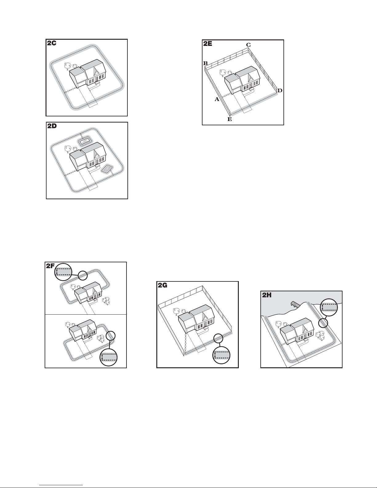
Exemples de dispositions d’installation
Exemple 1 :
boucle de
périmètre
(boucle simple)
Délimitation la
plus commune.
Elle permet à votre
chat de bouger
librement et sans
danger dans tout le
terrain (2C). Elle
peut aussi protéger
les jardins, et
les espaces
paysagers (2D).
Boucle double
Une boucle double doit être utilisée lorsque le périmètre ne couvre pas tous les côtés de votre terrain.
Avec une boucle double, le fi l d’antenne doit être séparé d’au moins 1 à 1,5 m pour éviter de désactiver le signal.
Souvenez-vous qu’une boucle double nécessite deux fois plus de fi l.
Exemple 2 (2E) : boucle de périmètre utilisant une
clôture existante (boucle simple)
Cette délimitation vous permet d’utiliser une clôture
existante et d’empêcher votre chat de sauter par-dessus
ou de creuser en dessous. Cette disposition réduit la
quantité de fi l à enterrer. En partant de l’émetteur de
clôture, faites passer le fi l par A, puis de A à B, B à C,
C à D, D à E, E à A, et torsadez les fi ls de A jusqu’à
l’émetteur de clôture. Reportez-vous à la section
« Installation du fi l d’antenne » pour plus d’informations
sur la fi xation du fi l à une clôture.
D
E
F
E
F
D
1-1.5 m
(3-5 ft)
C
1-1.5 m
(3-5 ft)
B
A
B
A
C
Exemple 3 (2F) : uniquement à
l’avant ou à l’arrière du terrain
(boucle double)
En partant de l’émetteur de clôture,
faites passer le fi l par A, puis de A
à B, B à C, C à D, D à E, E à F,
faites demi-tour et revenez jusqu’en
A, tout en gardant le fi l séparé d’au
moins 1 à 1,5 m. Torsadez le fi l de
A jusqu’à l’émetteur de clôture.
B
A
1-1.5 m
(3-5 ft)
Exemple 4 (2G) :
Délimitation frontale
uniquement
(Boucle double)
En partant de l’émetteur de
clôture, faites passer le fi l par A,
puis de A à B, et revenez de B
à A tout en gardant le fi l séparé
d’au moins 1 à 1,5 m. Torsadez
le fi l de A jusqu’à l’émetteur de
clôture.
E
B
A
C
1-1.5 m
(3-5 ft)
D
Exemple 5 (2H) : Accès à
un lac (boucle double)
À partir de l’émetteur de clôture,
faites passer le fi l par A, puis
de A à B, faites demi-tour et
allez vers C, puis de C à D, D
à E, faites demi-tour et revenez
jusqu’en A tout en gardant le
fi l séparé d’au moins 1 à 1,5 m.
Torsadez le fi l de A jusqu’à
l’émetteur de clôture.
26 www.petsafe.net

Exemple 6 (2J) : Boucle de fi l attaché à une clôture existante (double
30 torsades/m
10 torsades/pied
boucle)
Cette délimitation vous permet d’utiliser une clôture existante et d’empêcher votre
chat de sauter par-dessus ou de creuser en dessous. Cette disposition réduit la
quantité de fi l à enterrer. En partant de l’émetteur de clôture, faites passer le fi l par
A, puis de A à B, B à C, C à D, D à E, E à F, faites demi-tour et revenez
jusqu’en A,
fi l de A jusqu’à l’émetteur de clôture. Reportez-vous à la section
« Installation du fi l d’antenne » pour plus d’informations sur la fi xation du
fi l à une clôture.
tout en gardant le fi l séparé d’au moins 1 à 1,5 m. Torsadez le
1-1.5 m
(3-5 ft)
C
A
B
D
F
__________________________________________________
E
Étape
3
Positionnement du fil d’antenne
Posez le fi l d’antenne en suivant votre disposition et testez le système
AVANT d’enterrer le fi l ou de l’attacher à la clôture. Vous pourrez ainsi
modifi er votre disposition plus facilement si nécessaire. Travaillez
soigneusement. Une entaille dans l’isolation du fi l peut diminuer la force du
signal et créer une partie affaiblie d’où votre animal pourrait s’échapper.
Le signal peut être brouillé si le fi l d’antenne passe en parallèle ou à moins de 1,5 m
de câbles électriques, d’autres systèmes de délimitation, de câbles téléphoniques, des
câbles de télévision ou d’antenne ou de parabole. Si un croisement est nécessaire avec
un des éléments ci-dessus, il doit être à 90 ° (perpendiculaire) (3A).
Si une séparation d’au moins 3 m entre le fi l d’antenne et un autre système de délimitation ne
parvient pas à améliorer le signal, veuillez contacter le Service clientèle.
Pour torsader le fi l d’antenne
Torsadez le fi l d’antenne pour désactiver le signal et permettre à votre chat de passer cette zone
sans avertissement (3B). Pour être sûr que le signal est désactivé, il est recommandé de couper
et d’épisser le fi l d’antenne entre chaque section torsadée. Les gaines en plastique ou en métal
ne bloquent pas le signal. Vous pouvez torsader votre propre fi l en coupant deux longueurs
égales du fi l d’antenne et en les torsadant ensemble. Fixez une extrémité des fi ls à quelque
chose de solide et insérez l’autre extrémité dans un foret électrique. Tendez le fi l. Le foret
permet de torsader le fi l rapidement. Torsadez le fi l d’antenne 30 fois par mètre pour désactiver
le signal (2A). Une fois le périmètre délimité, insérez le fi l torsadé dans l’émetteur.
Pour épisser ou réparer le fi l d’antenne
Si vous avez besoin de plus de fi l d’antenne pour allonger la boucle, il faudra épisser les fi ls.
Notez l’emplacement de toutes les jonctions à titre de référence. Le fi l se casse souvent au
niveau des jonctions.
Dénudez environ 1 cm aux extrémités des fi ls d’antenne à épisser (3C). Vérifi ez que le fi l
d’antenne en cuivre n’est pas rouillé. En cas de corrosion, coupez-le pour pouvoir dénuder une
partie du fi l non rouillée.
Insérez les extrémités dénudées dans le connecteur et torsadez le connecteur autour des fi ls.
Vérifi ez qu’il n’y ait pas de cuivre exposé au-delà du connecteur. Faites un nœud à 7,5-10 cm
du connecteur (3D). Vérifi ez que le connecteur soit bien en place sur la jonction.
Une fois les fi ls joints, ouvrez le capuchon de la capsule remplie de gel et insérez le connecteur le plus profondément
possible dans le gel étanche (3E). Refermez le capuchon de la capsule (3F). Pour un bon fonctionnement du système,
la jonction doit être étanche.
Si la jonction se défait, l’ensemble du système sera touché par le dysfonctionnement. Vérifi ez que la jonction soit solide.
Des capsules et des connecteurs supplémentaires sont disponibles auprès de notre Service clientèle.
Fil d’antenne
90˚
0,952 cm
3
/8 in)
(
3 m
10 ft
3 m
10 ft
1
2
Câble enterré
0,952 cm
3
/8 in)
(
3F
3D
3E
www.petsafe.net 27
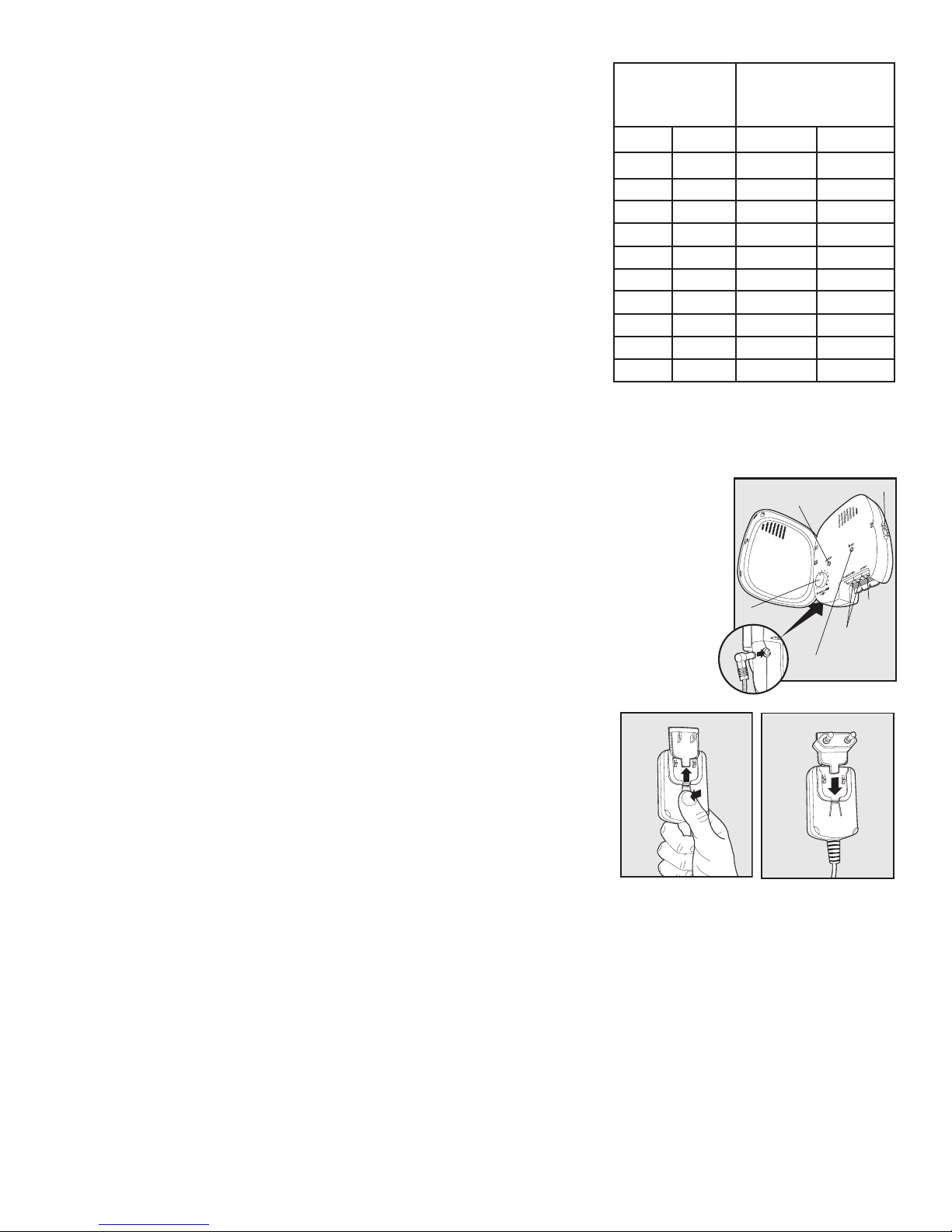
Fil d’antenne supplémentaire
Du fi l d’antenne à enterrer supplémentaire est disponible en bobines de
150 m dans le magasin où vous avez acheté le kit ou directement à notre
Service clientèle.
Remarque : Lors de l’ajout de fi l d’antenne supplémentaire, ce dernier doit
former une boucle continue.
Le tableau sur la droite indique la longueur approximative de fi l
d’antenne nécessaire pour une disposition carrée à boucle simple.
La longueur varie en fonction de la quantité de fi l torsadé et de la
disposition. Souvenez-vous qu’une double boucle nécessite deux fois
plus de fi l.
Zone à
délimiter
Ares Acres Mètres Pieds
10 1/4 127 415
13 1/3 146 480
20 1/2 180 590
40 1 255 835
80 2 360 1180
200 5 570 1870
400 10 800 2600
600 15 1000 3200
800 20 1100 3700
900 22 1200 4000
Longueur
approximative de
fi l nécessaire
__________________________________________________
Étape
4
Connexion des fils à l'émetteur de clôture
Fil d’antenne
1. Amenez le fi l d'antenne jusqu'à l'émetteur de clôture en passant par une fenêtre, sous
une porte, par une ventilation ou tout autre accès adéquat. Vous pouvez également
percer un mur.
2. Dénudez les extrémités du fi l d'antenne sur 1,3 cm.
3. Insérez le fi l d'antenne dans les bornes d’attache du fi l d’antenne sur l'émetteur de
clôture. Vérifi ez que les fi ls ne se touchent pas au niveau des bornes.
4. Mettez la molette de réglage de la largeur du périmètre sur 10. Ceci permet de régler la
zone d’avertissement à la largeur maximale.
5. Branchez l'adaptateur à la prise d’alimentation. La prise pour l'Amérique du Nord est
installée par défaut sur l'adaptateur, qui est également livré avec les prises européenne et
britannique. Pour changer la prise :
a. Poussez la languette sur l'adaptateur et retirez la prise en la faisant
glisser comme indiqué (4B).
b. Faites glisser la prise souhaitée sur l'adaptateur, comme indiqué(4C).
6. Le voyant d’alimentation et les voyants de boucle doivent s'éclairer. S'ils
ne s'éclairent pas, consultez la section « Dépannage ».
(4A)
4B 4C
4A
Molette de réglage de la
largeur du périmètre
Prise
d'alimentation
Sélecteur de longueur de fil
Voyant d’alimentation
Voyant de boucle
Bornes d'attache
du fil d'antenne
Prise
de terre
28 www.petsafe.net
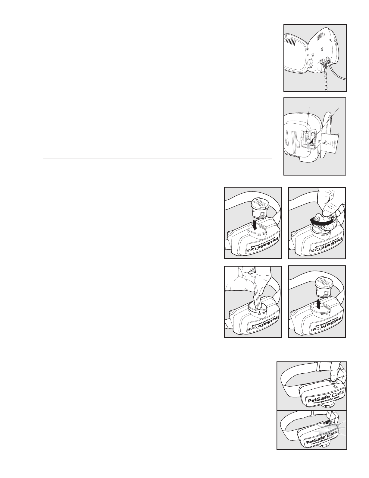
Étape
5
Fil de terre
Même si cela n'est pas nécessaire à son fonctionnement, la mise à la terre du système réduit
les risques de surtension pouvant endommager l'émetteur de clôture et l'adaptateur. Pour
mettre le système à la terre, il vous faut un fi l de terre plein (non toronné) (fi l en cuivre
isolé de calibre 14 à 18) et un piquet de mise à la terre avec une pince, que l'on trouve dans
les magasins spécialisés. Connectez une extrémité du fi l de terre à la prise de terre située
sur l'émetteur de clôture et l'autre extrémité au piquet de mise à la terre. Le piquet de mise
à la terre doit être enterré à au moins un mètre de profondeur et le plus près possible de
l'émetteur de clôture.
(4D)
4D
de terre
Fil
Fusible de protection
L'émetteur de clôture est équipé d'un fusible de 250 V et ½ A pour protéger le circuit
électronique du système en cas de surtensions. Pour accéder au fusible, retirez le cache à
l'arrière de l'émetteur de clôture. Un fusible de rechange est également fourni.
(4E)
Préparation du collier-récepteur
Insertion et retrait de la pile
Remarque : N’installez pas la pile lorsque le collier-récepteur est sur votre chat.
Ce collier-récepteur utilise une pile remplaçable PetSafe® (RFA-188)
spécialement conçue pour un remplacement plus simple et une
meilleure protection contre l’eau.
Pour activer le collier, insérez la pile (5A). À l’aide du bord de la clé
multifonctions (comme indiqué), tournez la pile dans le sens des
aiguilles d’une montre jusqu’à ce que la ligne verticale de la pile
pointe en direction de la position « ON » (5B). Si vous n’utilisez pas
le collier-récepteur PetSafe® immédiatement, laissez la ligne sur la
position « OFF ».
Pour retirer la pile, tournez la pile dans le sens inverse des aiguilles
d’une montre à l’aide du bord de la clé multifonctions (5C, 5D).
N’essayez PAS de couper ni d’ouvrir la pile. Veillez à respecter la
réglementation sur la mise au rebut des piles usagées.
Des piles de rechange PetSafe® sont disponibles chez de nombreux
revendeurs. Visitez notre site www.petsafe.net pour trouver un
revendeur près de chez vous ou consulter la liste des numéros de
téléphone de notre Service clientèle.
5A 5B
5C
4E
5D
Fusible de rechange
Fusible
Voyant lumineux bicoloure
Le voyant bicoloure indique l’état de la pile. Un clignotement vert toutes les 60 secondes indique que la pile est bonne.
Un clignotement vert toutes les 60 secondes indiquent que la pile est bonne. Si le voyant ne s’allume pas du tout, il est
temps de changer la pile.
Réglage du niveau de stimulation électrostatique
Veuillez lire toutes les étapes avant de régler le niveau stimulation électrostatique.
1. Une fois la pile installée, appuyez sur le bouton du niveau de stimulation jusqu’à ce
que le voyant lumineux du récepteur soit rouge (5E).
2. Le voyant lumineux du récepteur clignote plusieurs fois en rouge pour indiquer le
niveau de stimulation électrostatique (5F).
3. Vous pouvez augmenter le niveau stimulation électrostatique en appuyant sur le
bouton de niveau de stimulation et en le relâchant dans les 5 secondes qui suivent le
clignotement précédent.
Les niveaux de stimulation électrostatique vont de 1 à 5. Appuyez sur le bouton de niveau
de stimulation lorsque le collier-récepteur est au niveau 5 pour le faire revenir au niveau 1.
Consultez le tableau de fonctions et de réactions pour choisir le niveau de stimulation
convenant le mieux à votre animal.
www.petsafe.net 29
5E
5F
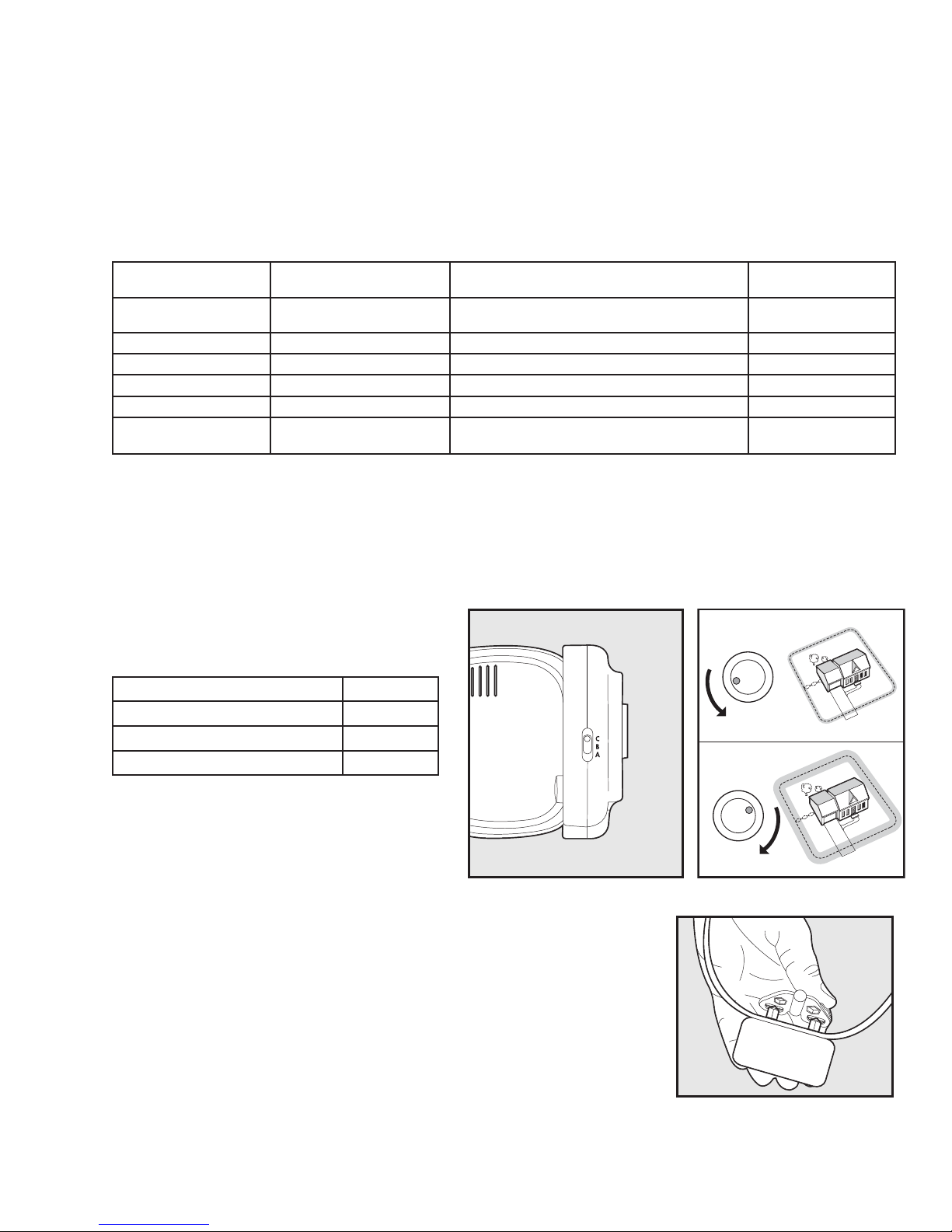
Si le collier est réglé au niveau 2 ou à un niveau supérieur, il augmente automatiquement le niveau de stimulation en
fonction du temps que votre animal reste dans la zone de stimulation électrostatique.
Le voyant lumineux du récepteur indique l’état de la pile (clignotement toutes les 60 secondes si la pile doit être remplacée).
Protection contre une stimulation excessive
Dans le cas improbable où votre chat s’immobiliserait dans la zone de stimulation électrostatique, cette protection limite
la durée de stimulation à 30 secondes. Le système bloque ensuite la stimulation jusqu’à ce que l’animal sorte de la zone
de stimulation électrostatique.
Tableau de fonctions et de réactions
Remarque : Commencez le dressage au niveau 2 et augmentez uniquement le niveau si votre chat ne réagit pas à cette stimulation.
Étape
6
Réaction du voyant
lumineux
1 clignotement 1
2 clignotements 2 Stimulation électrostatique faible Timide
3 clignotements 3 Stimulation électrostatique moyenne Timide à moyen
4 clignotements 4 Stimulation électrostatique moyenne à élevée Moyen à énergique
5 clignotements 5 Stimulation électrostatique élevée Très énergique
Clignotements toutes
les 4 à 5 secondes
Niveau de stimulation
électrostatique
Batterie faible
Fonction du collier-récepteur
Pas de stimulation électrostatique, signal
sonore seul
Comportement du
chat
_________________________________________________
Réglage de la largeur du périmètre et test du
collier-récepteur
Le sélecteur de longueur de fi l sur le côté de
l’émetteur de clôture a trois réglages (6A).
Le réglage B est utilisé pour la plupart des terrains.
Le tableau suivant indique quel réglage utiliser.
Quantité de fi l Paramètre
Jusqu’à 400 m
400-730 m
Plus de 730 m
Utilisez la molette de réglage de la largeur du
périmètre pour régler la largeur de la zone
d’avertissement et de la zone de stimulation
électrostatique (6B). Choisissez le périmètre le plus
large possible pour donner à votre chat les plus
grandes zones d’avertissement et de stimulation
électrostatique sans trop réduire la zone autorisée.
Nous recommandons une largeur de 3,7 à 6 m.
Remarque : La molette de réglage de la largeur du périmètre ne modifi e pas le niveau de
stimulation électrostatique.
Pour localiser les zones d’avertissement et de stimulation électrostatique, veillez à ce
que la pile du collier-récepteur soit bien installée, que le niveau de stimulation soit
sur 2 ou plus et que les contacts de la clé multifonctions soient contre les contacteurs
(6C). Pour des résultats optimaux, choisissez une partie où le fi l d’antenne est droit
sur au moins 15 m de long. Maintenez les contacts de la clé multifonctions contre les
contacteurs (6C). Marchez vers le fi l d’antenne en dirigeant les contacteurs vers le
haut et en tenant le collier-récepteur à la hauteur du cou de l’animal (6D) jusqu’à ce
que le collier sonne (6E) et que la clé multifonctions clignote.
Remarque : Le collier-récepteur est étanche, ce qui peut rendre le bip diffi cile à entendre.
Si le collier-récepteur ne sonne pas à l’endroit voulu, réglez la molette de réglage de
la largeur du périmètre. Tournez-la
B
C
A
6A
6B
5
4
3
28
1
0
5
6
4
3
28
1
10
0
6C
6
7
9
10
7
9
30 www.petsafe.net
 Loading...