


electronic
Quality is our Drive.
Assembly- and Commissioning Instructions
Safety Standstill Monitor
VersiSafe

Ver si Safe 1
as per 09/18 17800.10001
Table of Contents Page
1. Safety remarks 3
2. Conformity 3
3. EC Declaration of Conformity 4
4. Function 5
5. General description 6
5.1 Applications 6
5.2 Features 6
5.3 Funtion 6
5.4 Functional diagram 8
5.5 Functional description 8
6. Technical data 9
6.1 Input (L1 - L2 - L3) 9
6.2 Output 10
6.3 General data 10
6.4 Dimensions 14
6.5 Characteristics 15
7. Commissioning 15
7.1 Terminal connections 15
7.2 Setup and setting 16
7.3 Special applications and operation notes 17
8. Failure monitoring 19
8.1 Types of error 19
8.2 Failure indication 20
8.3 Failure treatment 21
9. Connection diagramm 24
9.1 with 3-phase motor 24
9.2 with single-phase motor 24
9.3 Typical connection combination with E-Stop 25
9.4 Typical connection combination with star delta timer, 2-channel connection of the
measuring inputs 26
9.5 Typical connection combination with star delta timer, 3-channel connection of the
measuring inputs 27
2VersiSafe
These commissioning instructions were prepared with great care. Nevertheless, PETER
electronic GmbH & Co. KG does not assume liability for damage resulting from mistakes
possibly contained in this manual. Technical changes that serve to improve the product are
subject to change without notice.
Disposal Instructions
Equipment containing electrical components may not be disposed of
together with domestic waste. It must be collected separately as electrical
and electronic waste according to local and currently valid legislation.
Notes and symbols used in these instructions
Note: Notes explain the advantages of certain adjustments or settings and help
you to make use of the device in the best possible way.
Warning notices: Read them carefully and follow them strictly!
Warning notices are indicated in order to protect you against danger or to
help you to prevent the device from being damaged.
Caution: Danger to life through electric shock!
When you see this sign, always make sure that the device is de-energized
and secured against unintentional energizing.

Ver si Safe 3
1. Safety remarks
Installation and setup of the VersiSafe must only be carried out by well trained staff,
with knowledge about all relevant standards for safety, accident avoidance and
control circuits. This manual must be read and understood before installation and
setup.
The VersiSafe is suitable to operate as a part in safety circuits of a plant or machine. Usually also
other components are part of these circuits. It is the liability of the builder of the plant or machine
to guarantee the complete safety function by selecting the correct components, wiring and
operation.
Also the correct tripping point and time delay setting of VersiSafe suitable for the application is in
the liability of the user.
When stocking, transporting and operating the VersiSafe the conditionsstated in the technical
data must be observed. Defective units must not be operated. Opening a device or making
unauthorised changes can influence the safety function and finish warranty.
When switching capacitive or inductive load over the output contacts appropriate protection
should be provided in order not to overload the contacts. In addition a fuse must be provided to
protect the contacts against welding (see technical data).
The unit should be panel mounted in an enclosure rated at IP 54 or superior. Dust and dampness
may lead to malfunction
be heeded. The permissible ambient conditions must be observed. In particular, the current limit
curve must be heeded.
Risk of fire or other thermal hazards!
The device may only be used for the applications described in the mutually applicable
operating instructions / data sheet. The notes in the respective documentation must
2. Conformity
In industrial linguistic usage the Safety Standstill Monitor of the type series VersiSafe are called
"devices", however, in the sense of the "device-safety-law", the "EMC-law" or the "EC machinery
directive" they are not devices or machines ready for use or connection but they are components.
It is only possible to define their final function, when these components are integrated into the
design and construction of the user.
To be able to use the devices to their intended purpose, it requires power supply networks
according to DIN EN 50160 (IEC38).
The user takes the responsibility that the user’s design and construction comply with the applicable legal provision.
The commissioning is strictly forbidden as long as the conformity of the final product with the
guideline 2006/42/EC (Machinery directive) is not proved.

4VersiSafe
3. EC Declaration of Conformity
EC Declaration of Conformity
The manufacturer / company placing the product on the market
(authorized representatives of the manufacturer / companies placing the product on the market
that are established within the Community)
Name / Address: PETER electronic GmbH & Co. KG
Bruckäcker 9
92348 Berg
hereby declares that the following product (device, component, unit) in the version as supplied
Product designation: Standstill monitor
Series / type designation: VersiSafe
Article number: 278...
Year of manufacture: 2007
complies with the provisions of the following EU-directives:
2014/30/EU
2006/42/EG
2011/65/EU
The following harmonized standards have been applied:
Basis of Testing
This EC Declaration of Conformity is no longer valid, if the product is modified or changed
without our agreement.
This declaration is issued under the sole responsibility of the signatory.
Berg, 29.06.2018 Dr. Thomas Stiller, Managing director
(place, date) (signatory and function of the signatory) (signature)
Electromagnetic compatibility
Machinery Directive
RoHS-Directive
EN ISO 13849-1:2015
IEC 61800-5-1:2016
IEC 61508 Parts 1-7:2010
EN 61000-6-1:2007
EN 61000-6-3:2007 + A1:2011
EN 61000-6-7:2015
IEC 62061:2005 + A1:2012 + A2:2015
IEC 61800-5-2:2016
EN 61000-6-2:2005
EN 61000-6-4:2007 + A1:2011

Ver si Safe 5
4. Function
The VersiSafe is connected to the motor terminals and measures the induced back emf voltage of
a freewheeling motor. 2 redundant measuring channels are used (L2-L1 and L3 L1). If the back
emf voltage drops to 0 simultaneously in both channels this indicates standstill and the output
relay is energised.
To adopt the unit to all different types of motors and applications the voltage threshold indicating
standstill on VersiSafe is adjustable. Also the time delay between detection and energisation of
the relay is adjustable (standstill time t
In addition the unit detects broken wire on the measuring inputs L1 / L2 / L3. If broken wire is
detected the output relays goes into safe state (as with running motor). This state is stored and
can be reset by bridging terminals X3-X2.
The input signals of both channels are permanently compared. If the signals are different for more
then 2.5 sec a simultaneity failure isdetected. This failure resets when both input channels
receive simultaneous signals with the same level.
To the terminals X1-X2 the feedback circuit of external contactors (used for contact
reinforcement) is connected (NC contact). If no feedback circuit is required, these terminals must
be linked. Open terminals will cause a failure message.
Circuit diagram
54
53
X3 33
X1
X2
11 23 33 43 53 A3+
K1
K2
A3
ON
A4
+
ERR
).
s
L1
11
12
L3
L2
23
43
54
ON ERR24 34 44
A412
44
34
24
A1
A2
M9163_d
Warning:
The terminals X1 - X2 - X3 has no galvanic separation to the measuring ciruit
L1 - L2 - L3. They must be controlled with volt free contacts.

6VersiSafe
Indicators
green-red LED „UH“: green on, when operation red on, with internal error
yellow-green LED „OUT“: yellow on, at EMK > U
flashes green at time progression of t
permanent on, when output contacts are enable
an
s
red LED „ERR“: flashes at error in measuring and
feedback circuit and low auxiliary
voltage UH (see flashing codes)
5. General description
5.1 Applications
Safe standstill detection on 3- and single-phase motors, e.g. to enable gate interlocks on machine
tools or to activate hold in brakes.
5.2 Features
• According to
- Performance Level (PL) e and category 4 to EN ISO 13849-1
- SIL-Claimed Level (SIL CL) 3 to IEC/EN 62061
- Safety Integrity Level (SIL) 3 to IEC/EN 61508 and IEC/EN 61511
• Safe standstill detection on 3- and single-phase motors
• No external sensors necessary
• Independent of direction
• Broken wire detection
• Forcibly guided safety contacts: 3 NO contacts, 1 NC contact for AC 250 V
• 2 semiconductor monitoring outputs
• 1 monitoring output (NO contact)
• Adjustable voltage setting
• LED indicators for standstill, event of line breakage and operation voltage
• Suitable for operation with inverters
• Width 45 mm
5.3 Funtion
The VersiSafe can be used for standstill detection on all 3-phase, single phase and DC motors,
that generate a voltage caused by remanence when freewheeling. As the voltage level Uan for
standstill monitoring and the time delay t
switched on, are adjustable, the function can be adopted to different motors and applications.
, after detection of standstill until the safety relays are
s

Ver si Safe 7
Terminals and settings
L1 - L2 - L3: connection to monitored motor
11 - 12: safety contacts (NO)
23 - 24, 33 - 34, 43 - 44: safety contacts (NC)
53 - 54: monitoring contact (C/O)
X1 - X2: connection of feedback circuit
(for external contactors)
X2 - X3: manual reset for external faults
A1 - A2: auxiliary supply (UH)
A3(+) - A4: supply for semiconductor outputs
ON: semiconductor output indicates state of safety contacts
ERR: semiconductor output indicates failures
Poti „Uan“: adjustment of voltage level for standstill detection
Poti „ts“: adjustment of time delay before activation of safety contacts
Attention:
The outputs 53-54, ON and ERR are only monitoring outputs and must not be used in
safety circuits!

8VersiSafe
5.4 Functional diagram
U
H
A1/A2
motor speed /
voltage
L1/L2/L3
line breakage
L1/L2/L3
23-24
33-34
43-44
53-54
A3-ON
11-12
A3-ERR
eon
auxiliary voltag
own
stop
motor on
start up delay time U
standstill detected
motor runs d
t
E
standstill delay time t
motor runs down
2
reset X3-X
M9647_a
voltage level
U
an
eakage
X3-X2
line br
reset
line breakage
Motor Ein
t
E
s
t =2...2,5s
H
E
5.5 Functional description
The auxiliary voltage is connected to the terminals A1-A2; the LED „UH“ lights up green. On
undervoltage or missing auxiliary supply the safety outputs are disabled.
If semiconductor monitoring outputs are used, their supply voltage must be connected to A3(+)A4.
A motor connected to the terminals L1-L2-L3 of the VersiSafe generates a voltage when running
down (motor is switched off). The voltage is proportional to the speed and caused by residual
magnetism (remanence).
This voltage is measured redundant on 2 input channels via the terminals L2 and L3 with L1 as
common reference.
If the voltage drops on both channels below the adjusted value Uan, the unit detects standstill.
When the terminals X1-X2 of the feedback circuit are bridged and the time delay ts is finished, the
safety contacts 23-24, 33-34 and 43-44 close while contact 11-12 opens. All 4 contact paths have
2 positive guided contacts of 2 safety relays wired in series.

Ver si Safe 9
At the same time the monitoring relay energises (53-54 closes), the semiconductor output „ON“ is
switched on and the LED „OUT“ lights green. During time delay ts this LED flashes.
If the voltage measured on terminals L1-L2-L3 of VersiSafe rises over the adjusted value plus
hysteresis in at least one channel (the motor is switched on or the shaft turns mechanically), the
positive guided output contacts are switched off immediately (contacts 23-24, 33-34 and 43-44
open while contact 11-12 closes). The monitoring relay de-energises (53-54 opens), the semicon
ductor output „ON“ goes off and the LED OUT“ lights yellow (= U
Feedback circuit X1 - X2
If the safety contacts control external contactors/components (e.g. to re-enforce or multiply the
contacts) the safety function of them must be monitored.
This is done with the feed back circuit (terminals X1-X2) to which the NC contacts of the
contactors/components must be connected. (see also wiring diagrams).
The VersiSafe will only enable its safety output if the feedback loop X1-X2 is closed while standstill is detected, i.e. the external contactors/components are in initial state (NC contacts are
closed).
The feedback circuit X1-X2 must be closed as long as the safety outputs because of running
motor or external failure) are not enabled. If not the failure „feedback circuit“ is indicated.
If the feedback circuit is not used, the terminals X1-X2 must be bridged.
6. Technical data
6.1 Input (L1 - L2 - L3)
Measuring-/Motor voltage: max. AC 690 V
Input resistance: 500 kOhm
Response value Uan: 20 mV ... 400 mV, adjustable
Response value dependent on frequency
special variant 0,2 ... 4V
over adjusted value).
an
-
Input frequency (Hz): 50 100 200 400 600 1k 1,5k 2k
Multiplication factor for Uan: 1,0 1,1 1,2 1,5 2,0 2,8 5 8
Hysteresis (for detection
of running motor): 100 %
Release delay for detection
of running motor: < 100 ms
Standstill time delay ts: 0,2 ... 6s adjustable
Auxiliary voltage U
(A1 - A2): AC 230 V, AC 400 V, DC 24 V
H
Recommended fusing: 2 A
Voltage range
AC: 0,8 ... 1,1 U
DC: 0,9 ... 1,2 U
N
N
Nominal consumption: 5 VA, 3 W

10 VersiSafe
Nominal frequency (AC): 50 / 60 Hz
Frequency range (AC): 45 ... 65 Hz
max. residual ripple (DC): 10 %
Start up delay when
connecting U
6.2 Output
Contacts
(saftey contacts)
VersiSafe 230VAC: 3 NO contacts, 1 NC contact
The NC contacts 11-12 can only be used for monitoring.
Contact type: relay, positive guide
Nominal output voltage: AC 250 V
Thermal current Ith: 5 A (bis 40°C)
Quadratic total current: see derating curve
Switching capacity
to AC 15
NO contact: AC 3 A / 230 V IEC/EN 60 947-5-1
NC contact: AC 1 A / 230 V IEC/EN 60 947-5-1
to DC 13: DC 1 A / 24 V IEC/EN 60 947-5-1
Electrical contact life
to 5 A, AC 230 V cos phi = 1: 2 x 10⁵ switching cycles
Fusing of the
safety contacts: max. fuse rating 4AgL
Max. operating frequency: 1200 / h
Mechanical life: => 50 x 10
Semiconductor monitoring
output: 100 mA DC 24 V, plus switching,
NO monitoring contact: 3 A AC 250 V (closed when enabled)
at standstill: 0,4 ... 0,8 s + adjustable t
H
line circuit breaker C6A
6
switching cycles
galvanic separation; supply via
A3+ / A4 for output; „ON“ and „ERR“
s
6.3 General data
Nominal operating mode: continuous operation
Temperature range
operation: - 25 ... + 60°C
(+ 40°C with max. contact current, see Derating)
storage: - 40 ... + 75°C
Clearance and creepage distance
rated impuls voltage/pollution degree: IEC 60 664-1
Contacts 11/12, 23/24,
33/34, 43/44 against all others: 6 kV / 2

Ver si Safe 11
Contacts 11/12, 23/24,
33/34, 43/44 against each others: 4 kV / 2
Indicator contact 53/54
against all others: 4 kV / 2
Semiconductor outputs A3+/
ON / ERR / A4 against all others: 6 kV / 2
Auxiliary voltage A1 / A2
against all others
at auxiliary voltage AC: 6 kV / 2
at auxiliary voltage DC: 4 kV / 2
Control terminal X1 / X2 / X3: no galvanic separation to L1 / L2 / L3
EMC IEC/EN 62 061
Interference suppression
Auxiliary voltage AC: limit value class B EN 55 011
Auxiliary voltage DC: limit value class A*) EN 55 011
*) The device is designed for the usage under industrial conditions (Class A, EN 55011). When
connected to a low voltage public system (Class B, EN 55011) radio interference can be
generated. To avoid this, appropriate measures have to be taken.
Degree of protection
Housing: IP 40 IEC/EN 60 529
Terminals: IP 20 IEC/EN 60 529
Enclosure: thermoplastic with VO behaviour
Vibration resistance: amplitude 0,35 mm
Climate resistance: 25 / 060 / 04 IEC/EN 60 068-1
Terminal designation: EN 50 005
Wire connection: DIN 46 228-1/-2/-3/-4
Screw terminals (integrated): 1 x 4 mm
Insulation of wires
or sleeve length: 8 mm
Wire fixing: Plus-minus terminal screws M 3,5
Mounting DIN rail IEC/EN 60 715
Weight: approx. 400 g
according to UL subject 94
frequency 10 ... 55 Hz IEC/EN 60 068-2-6
2
1 x 2,5 mm2 stranded ferruled or
2 x 1,5 mm
solid or
2
stranded ferruled or
2 x 2,5 mm2 solid
box terminal with wire protection or
cage clamp terminals

12 VersiSafe
Safety related data
Values according to EN ISO 13849-1:
Category: 4
PL: e
MTTFd: 93 a
DC
: 99,0 %
avg
dop: 365 d/a (days/year)
hop: 24 h/d (hours/day)
t
: 28,8E+03 s/Zyklus
Zyklus
Values according to IEC EN 62061 / IEC EN 61508 / IEC EN 61511:
SIL CL: 3 IEC EN 62061
SIL: 3 IEC EN 61508 / IEC EN 61511
HFT*: 1
DC: 99,0 %
PFHD : 4,10E-10 h
T1: 20 a (years)
*)HFT = Hardware-Failure Toleranz
= 1 /8 h (hours)
-1
Demand to our device based on the evaluated
Intervall for cyclic test of the safety function
neccessary safety level of the application
acc. to EN ISO 13849-1 PL e with
once per month
Cat. 3
PL d with
once per year
Cat. 3
acc. to
IEC/EN 62061,
IEC/EN 61508
SIL CL 3,
SIL 3
with HFT = 1
SIL CL 2,
once per month
once per year
SIL 2
with HFT = 1
acc. to EN 61511 SIL 3 once per year
Info: The values stated above are valid for the standard type.
Safety data for other variations are available on request.
The safety relevant data of the complete system has to be determined by the
manufacturer of the system.

Ver si Safe 13
UL -Data
The safety functions were not evaluated by UL. Listing is accomplished according to
requirements of Standard UL 508, „general use apllications“.
Measuring-/Motor voltage: max. AC 600V
Ambient temperature: -25 ... +60°C, (+40°C with max. contact current,
Switching capacity
safety contacts
(11/12, 23/24, 33/34, 43/44)
Ambient temperature 40°C: Pilot duty B300
Ambient temperature 60°C: Pilot duty B300
Switching capacity
indicator contact (53/54): 3A 250VAC G.P.
Wire connection: 60°C / 75°C copper conductors only
Fixed screw terminal: 1x AWG 20 - 12 Sol/Str Torque 0.8 Nm or
Device with auxiliary
voltage Uh 24V DC: Device must be supplied with a Class 2 or a Voltage /
Info: Technical data that is not stated in the UL-Data, can be found in the
technical data section.
see Derating)
5A 250VAC G.P.
5A 24VDC G.P.
2A 250VAC G.P.
2A 24VDC G.P.
2x AWG 20 - 14 Sol/Str Torque 0.8 Nm
Current limeted Power Supply.

14 VersiSafe
6.4 Dimensions
90
45
121
All dimensions in mm.
Standard type
VersiSafe AC 230 V 50/60 Hz
Article number: 27800.69000
• Safety output: 3 NO contacts, 1 NC contact
• Auxiliary voltage U
• Response value U
• Standstill time t
: AC 230 V
H
: 20 ... 400 mV
an
: 0,2 ... 6 s
s
• 1 semiconductor and 1 NO contacs for indicator output
• 1 semiconductor for fault indicator output
• Width: 45 mm

Ver si Safe 15
6.5 Characteristics
2
2
(A)
I
80
70
60
50
40
30
20
10
T( C)
0
10 20 30 40 6050
Quadratic total current
=I2+I2+I
I,I,I
123
2
1
23
- current in contact paths
max. permitted current up to 40˚Con 3 contact paths = 5A
222 2
(5 5 +5 = 75A )
+
max. permitted current up to 60˚Con 3 contact paths = 2A
222 2
(2 +2 = 12A )
+2
Derating curve for contact currents of safety contacts
M9658
°
7. Commissioning
7.1 Terminal connections
The VersiSafe has to be connected according to connection examples or in a similar way. The
connection of DC- motors is made as with single phase AC-motors.
L1 - L2 - L3
The measuring wires L1-L2-L3 have to be connected directly to the windings of the monitored
motor (not via transformers) in order to provide a correct broken wire detection for the connection
wires and motor windings.
The motor windings must not be disconnected from the measuring wires by motor contactors,
because broken wire detection is activated and standstill monitoring is disabled.
Interference to the measuring wires should be avoided as no standstill may be detected by the
VersiSafe. If possible the measuring wires should be run separately from the motor wires or
screened wires should be used. In this case the screen can be connected at the
motor side.

16 VersiSafe
A 1 - A2
Connection of the auxiliary supply, recommended fuse : 2A.
A3+ / A4
DC 24 V supply (12 … 30 V) for the semiconductor monitoring outputs „ON“ and „ERR“, if these
are used.
11-12, 23-24, 33-34, 43-44
Safety output contacts, connection according to the connection examples or similar.
Recommended fuse: 5 A fast acting, to avoid welding of the contacts in the case of external
wiring or component failures. See also technical data.
53 - 54
Monitoring contact to indicate the state of the safety output (non safety contact).
X1 - X2 (feedback circuit)
Connection of NC contacts of external components or contactors for contact re-enforcement,
must be linked if not used.
X2 - X3
Connection for manual or auto reset, connection is made according to he required application.
When monitoring DC motors or in the case of DC-braking the broken wire / offset failure will be
shown during operation.
In this case the terminals must be linked because if storing the failure would not allow activation of
the safety contacts at standstill.
Attention:
The terminals X1-X2-X3 have electrical connections to the measuring inputs L1-L2-L3. Volt
free contacts must be used for bridging. If terminal 3 should be controlled by a PLC via an
interface relay this must have the necessary insulation between the motor voltage (mea
suring input) and PLC potential.
-
7.2 Setup and setting
Preparation
• Motor on standstill
• Terminals L1-L2-L3 connected to the motor windings
• Provide link on terminals X1-X2
• Provide also link on X2-X3 on DC motors or DC braking
• Adjust U
• Adjust t
to minimum (20 mV)
an
to minimum (0,2 s)
s

Ver si Safe 17
Connect correct auxiliary voltage to terminals A-A2
==>After 1 sec the LEDs „UH“ and „OUT“ light up green and the safety contacts are switched on.
Also the monitoring relay and the semiconductor output „ON“ must be activated.
If standstill is not detected (LED „OUT“ lights yellow), possibly interference is coupled on the
measuring circuit. Adjust U
Start of motor
==>LED „OUT“ changes colour to yellow. The output relays and the semiconductor output „ON“
switch off. On DC motors the LED „ERR“ starts to flash after 2 s with flash code 2 and the output
„ERR“ comes on.
Stop of motor - run down or DC braking
The speed at which standstill is detected (yellow LED „OUT“ changes to green/green flashing)
can be adjusted on Potentiometer „U
delay must possibly be increased to avoid switching on and off of the output relays. Possibly this
effect can also be avoided by slightly increasing U
green.
If standstill detection shall only take place at very low speed of the motor, U
minimum. By increasing the delay time t
A longer time delay will also guarantee standstill detection only when the motor has already
stopped turning. (especially on motors that generate only a small remanence voltage).
On slow decrease of motor speed it is possible that a simultaneity failure occurs (see failure
monitoring) when the measuring channels reach the tripping values slowly and not within 2.5 sec.
To avoid this failure a single phase connection could be the solution (to make sure that both
inputs get the same signal) or the increase of the setting value U
If the run down time of the motor is short ts can be set to a minimum (0.2 s). This is suitable in
production systems to shorten machine cycles.
higher or screen the measuring wires.
an
“. When the run down is very slow or irregular the time
an
. During time delay ts the LED „OUT“ flashes
an
a possible pulsing of the output relays can be avoided.
s
is set normally to
an
.
an
Warning:
It is the responsibility of the user to adjust Uan and ts in a way that standstill
detection and enabling of the safety contacts in the application is only
possible when danger to men and material by the rotating can be excluded.
7.3 Special applications and operation notes
Motors with switched windings
(e.g. star delta starters, reversing circuits, multi speed motors)
With these applications please make sure, that the measuring inputs must be linked via the motor
windings. An open connection will result in broken wire indication and disable the safety contacts.
When connecting the VersiSafe to a 3-phase motor with star delta starter the star contactor must
be energised while the motor is switched off, in order to achieve closed circuits between L1-L2-L3
via the motor windings.

18 VersiSafe
If it is not possible to switch in the star contactor after the motor is switched off, the measuring
inputs of the VersiSafe have to be connected like a single phase connection. L2-L3 are bridged
and connected to one end of a motor winding and L1 to the other end of the same winding.
For reversing circuits and multi speed motors please follow the same procedure.
If in a 3-phase connection of VersiSafe windings are switched over, and the interruptions of the
measuring circuits are longer then 2 s, the standstill monitor detects broken wire. In order not to
store this failure, the unit should work with auto reset.
Operation with DE motors
The VersiSafe can be used on DC motors if these generate a remanence voltage during run
down.
The connection is made similar as with a single phase motor.
As the remanence voltage in this case is normally a DC voltage the unit will detect a broken wire /
offset failure and indicate it on LED „ERR“ and semiconductor output „ERR“. Taking this in mind
and operating the unit with auto reset for these failures the unit can be used for safety standstill
monitoring.
Operation with electronic motor controller
(inverters, DC-brakes)
The operation of VersiSafe to detect standstill on motors with electronic motor control is possible
if the control units do not generate any voltage n standstill. (NO position control on inverters, no
DC voltage on brakes after standstill).
If the inverter produces a DC offset or a DC brake is active, an offset or broken wire failure is
indicated on LED „ERR“ and semiconductor output „ERR“. This error resets automatically if on
terminals X2-X3 automatic reset is selected.
When there are inverters in the installation it is recommended to use screened measuring wires
to the motor. The screen can be connected to the motor.
Attention
If the motor current is run down by inverters or softstop modules in a slow
way the motor may be de-magnetised. It is necessary to check if the
remaining remanence voltage is sufficient to guarantee a correct and safe
standstill monitoring. At high frequencies an increasing damping of the
measuring inputs has to be taken into account (see technical data
Measuring input „response value dependant on frequency“).

Ver si Safe 19
8. Failure monitoring
8.1 Types of error
The VersiSafe includes a number of facilities to to detect failures that could influence the safety
function of the module. The failure check is carried out on power up of the unit and in cycles
during normal operation.
If a failure occurs the output relays switch off. The failure state is indicated with the LEDs „ERR“
and „UH“ and the semiconductor output „ERR“ switches on.
With safety relevant failures the unit differentiates between external failures (broken wire / offset,
simultaneity failure, feedback circuit failure) and internal failures.
Broken wire / offset failures and feedback circuit failures can be stored or automatic reset after
removing the fault. (see chapter failure storing).
Broken wire / offset
The connection wires between VersiSafe and motor are continuously monitored for broken wire
and on a DC-voltage offset higher then U
In the case of a broken wire or offset failure the output relays are switched off immediately and the
LED „OUT“ lights yellow.
In addition a failure signal comes up with delay (on broken wire after 2s on offset failure after 8 s):
the semiconductor output „ERR“ switches on and the LED „ERR“ flashes with failure code 2 or 3
depending on the failure located either between L1-L2 or L1-L3.
Simultaneity of the measuring signals
As additional safety feature the 2 input signals (L2 and L3) are compared continuously. This
allows to detect also internal failures in one measuring channel.
If the signals are different for at least 2.5 s (one channel >U
is detected. The semiconductor output „ERR“ is switched on and the LED „ERR“ flashes with
failure code 5.
If the measured signals return to the same level <Uan the error remains stored and the outputs are
disabled.
The simultaneity failure is only reset when both channels return to > Uan. If after that both
channels drop below the setting value, get < U
Failure in feedback circuit X1-X2
As already mentioned the failure code „feedback circuit“ occurs when the outputs are disabled
and there is no connection between terminal X1-X2. The semiconductor output „ERR“ is switched
on and the LED ERR“ flashes with failure code 4.
Also when both input signals drop now to <U
failures are present the feedback circuit failure remains active and the outputs remain disabled.
If the feedback circuit is now closed and the unit is on auto reset for external failures (see failure
storing) the output relays are enable and switch on.
.
an
the other <U
an
the out relays will switch on.
an
) simultaneity failure
an
and besides the open feedback loop no other
an

20 VersiSafe
Potentiometer error
To achieve the required safety when adjusting the voltage threshold for standstill detection, ech
setting function is realised with 2 potentiometers having one common setting knob. If on 2 corres
ponding potentiometers a different setting is detected the potentiometer error Uan or ts is
displayed.
To remove the failure please try to readjust the potentipometer. Please make sure that you feel
the detent.
Internal device failure
Internal failures are always stored, independent of the reset input X3 and cause the output relays
immediately to switch off, the semiconductor output „ERR“ to switch on and the LED „UH“ to
change it’s colour from reen to red.
Examples for internal failures:
• Failure on safety relays e.g. welded output contacts
• Internal failures on measuring channels and measuring circuits
• Internal failures on control circuits for the safety relays
• failures on setting potentiometers for U
• Undervoltage failure (LED „ERR“ flashes with failure code 1)
8.2 Failure indication
Failure indication with flash code of LED „ERR“
The flash codes indicate failures caused externally (see diagram on first page).
A series of flash pulses 1-5 followed by a slightly longer space is displayed. The flash code
indicates the type of failure. If several failures are present at the same time only the failure with
the highest priority (lowest flash code) is shown. When this failure is removed the other existing
failures are displayed in the same way according to their priority.
an
and t
s
-
Failure storing / reset (terminals X2-X3)
With the external failures broken wire/offset and feedback circuit the operator can choose
between manual and automatic reset after the failure is removed.
X2-X3 open: manual reset
X2-X3 closed: automatic reset
Attention:
The a.m. storing function of the external failures broken wire /offset, and feedback circuit
is not a safety function. I.e. in respect to safety aspects it can not be regarded as
guaranteed. The reset for these failures must be therefore regarded as auto reset after
removing the faults.
Internal device failures that could occur in seldom cases (e.g. caused by temporary interference) can be reset by switching the supply voltage off and on. If a reset is not possible
also if the voltage is applied correctly, the device could be defective and should be sent
back to the manufacturer for examination or repair.

Ver si Safe 21
undervoltage
at U
H
wire-break/offset
on L2
wire-break/offset
on L3
failure in feedback
circuit X1-X2
simultaneity failure
signal L2/L3
potentiometer error
U
an
potentiometer error
t
s
t
8.3 Failure treatment
Failure:
The unit enables the safety outputs while the motor is still turning (LED OUT“ lights green).
Solution:
Reduce setting of Uan if necessary to minimum. If the outputs are still enabled a wiring problem
on the measuring wires could be the reason (short circuit on terminals L2/L3 to L1) or the motor
generates only a very low remanence voltage. Please check connection of measuring inputs to
motor winding according to the connection examples.
M9648_c
Failure:
The output contacts are enabled to early (motor has not finally stopped):
Solution:
Adjust setting value Uan to lower level. Additionally the delay time ts could be increased.
Failure:
Output contacts remain disabled while the motor is already on standstill
Solution:
Observe status of indicator LEDs:

22 VersiSafe
1. LED „UH“ lights green?
If yes, go to 2.
has undervoltage or the unit has an internal device failure.
If no, U
H
(Internal failures can occur in the case of undervoltage, welded safety output contacts or
seldom because of interference)
==> switch supply voltage off and on. If the failure still exists in spite of correct auxiliary
supply UH the unit could be defective and has to be sent to manufacturer for test or
repair.
2. 2. LED „ERR“ (red) flashes with code 1?
If no, go to 3.
If yes, the unit has detected undervoltage
==> Apply correct auxiliary voltage
3. LED „OUT“ flashes green?
If no, go to 4.
If yes, standstill is detected, but the time ts till enabling of the outputs is not elapsed.
==> wait till time ts is finished.
If after 6 s the outputs are not enabled, the measuring input L1-L2-L3 receives intermittent
voltage peaks that are higher then U
This should normally be indicated by intermittent yellow flashes on the LED).
==> Adjust U
cables).
to a higher value, clear interference on measuring wires (use screened
an
4. 4. LED „OUT“ lights yellow?
If yes, the voltage on the measuring input is higher then the adjusted value U
If no, LED is off
Standstill is detected (voltage on measuring input is <U
because
a) Feedback circuit X1-X2 is not closed or
b) a simultaneity failure occurred (see failure monitoring) or
c) a previous failure ( broken wire / offset, feedback circuit) is still
stored (terminals x2-x3 are not linked.
The type of failure is indicated by flash code on the red LED „ERR“:
a) flash code 4 (feedback circuit not closed)
b) flash code 5 (simultaneity fault of the measuring signals on L2 L3)
c) code 2, 3 or 4 depending on priority and failure.
==> - close feedback circuit
- Bridge terminals X2-X3 (manual reset)
If now still the simultaneity failure (flash code 5 on LED „ERR“) is indicated it can be
reset by switching the auxiliary supply off and on. The reset also takes place, when
both input signals rise above Uan e.g. when starting the motor. If the simultaneity
failure remains active after start of the motor (e.g. because of short circuit between
L2-L1 or L3-L1) the wiring of the measuring circuit has to be checked according to
the connection example.
If the simultaneity failure occurs often e. g. on slow decease of the motor speed,
the problem can be solved by increasing the tripping value Uan or/and by making
a single phase instead of a 3-phase connection of the measuring circuit to the motor.
.
an
; go to 5.
an
) but the outputs are not enabled
an

Ver si Safe 23
5. LED „OUT“ lights yellow while the motor is on standstill
If the yellow LED „OUT“ is on this indicates that the measuring inputs
still receive an input signal higher then the adjusted value U
Observe in addition the LED „ERR“:
a) if it stays off after a time of 8 s the problem could be a interference
or residual voltage (induced AC voltage) on the measuring inputs
==> Increase the setting of U
an
If this shows no result, or if an increase is not wished, the interference to the
measuring lines must be reduced e.g. by creening, shortening or separating the
wires, Test: Disconnect motor and short circuit terminals L1-L2-L3 on the unit, the
yellow LED must change to green or green flashing.
b) if the red LED flashes code 2 the unit has detected broken wire or DC voltage offset
between the measuring inputs L1 and L2 (or between L1 and L2 and L1 and L3).
c) if the red LED flashes code 3 the unit has detected broken wire or DC voltage offset on
measuring input L3
In the 2 last cases the wiring between VersiSafe terminals L1-L2-L3 and the motor
terminals has to be checked on interruption. Possibly the interruption comes from disregarding the operating remarks for motors with switchable windings (see remarks).
If failures by interruption of the input circuits can be excluded the failure can result from a DC
voltage offset > Uan. This can come from motor ontrollers like inverters or DC brakes that are not
completely switched off and supply a DC-voltage to the measuring circuit (check with Voltmeter).
If the DC content is only minor, the failure can be removed by increasing the setting value Uan
The yellow LED „OUT“ must change to green or green flashing. If not the motor controllers must
be switched off in a way that standstill can be detected correctly.
an
Failure:
While motor is on operation a failure is indicated.
If the LED „UH“ lights red, an internal failure occurred.
Solution:
Switch auxiliary supply off and on again (see 1.)
If the LED „ERR“ indicates a failure the flash code shows the type of fault and how to remove it.
Flash code 2 or 3 are normal during operation of DC motors. If the terminals X2-X3 are bridged,
The failure is reset automatically at standstill and the output relays are enabled. The same is valid
for operation with electronic controllers, if these produce a DC voltage e.g. during braking of a
DC-brake.

24 VersiSafe
PE L1 L2 L3
K4 K5
L1
L2
L3
X1
X2
X3
LH5946
M
3~
M9649_b
N
L
23 33 4311A1 A3+ A4
24 34 4412 ON ERRA2
K4
K5
motor contactor
53
54
LPE N
K4 K5
L1
L2
L3
X1
X2
X3
LH5946
M
1~
M9650_b
N
L
23 33 4311A1 A3+ A4
24 34 4412 ON ERRA2
K4
K5
motor contactor
53
54
9. Connection diagramm
9.1 with 3-phase motor
suitable up to SIL3, Performance Level e, Cat. 4
9.2 with single-phase motor
suitable up to SIL3, Performance Level e, Cat. 4

Ver si Safe 25
A1
On
K4
K4
F2
S11 S12 S22
13 23 33 41
S21 S33 S34 14 24 34 42 A2
Entriegelung
Unlock
F1
Off
Not-Aus
E-Stop
Open
Auf
Stillstandswächter
Stand-Still-Monitor
Détecteur de vitesse zéro
LH5946
L1
K4
L2
L3
N
Not-Aus-Modul
E-Stop-Modul
Module d'arrêt d'urgence
LG5925
M9165_f
A1
11
53
54
23
24
43
A3 ON
ERR A4
12
+
44
X1
X2
A2
33
34
L1 L2 L3
Meldelampe
Signal lamp
*
*
Lampe de signalisation
Meldung an
Steuerung
übergeordnete
Signal to SPS
Signalisation à la
* optional
commande supérieure
M
3
+24V
E0
E1
...
SPS / PLC / API
Déverrouillage
Ouvert
Arrêt d'urgence
9.3 Typical connection combination with E-Stop
suitable up to SIL3, Performance Level e, Cat. 4

26 VersiSafe
9.4 Typical connection combination with star delta timer, 2-channel connection of the measuring inputs
suitable up to SIL3, Performance Level e, Cat. 4
L1
L2
L3
fuse
main switch
N
F
off
F
N
N
N
d = star delta timer
N = mains contactor
= star-contactor
= triangle contactor
on
A1
dN
A2
BC7936N
U1
17
27
d
18
28
A1 23 33 L1 L2 L3
LH5946
24 34A2
K4 K5
X1
X2
V1U2W1
M
3~
W2
K4
K5
V2
M9967_a
Ver si Safe 27
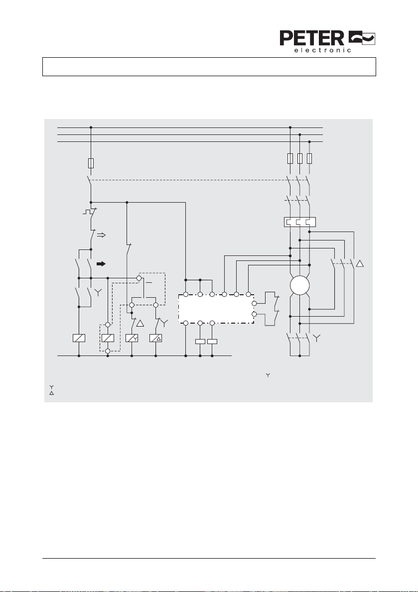
9.5 Typical connection combination with star delta timer, 3-channel connection of the measuring inputs
suitable up to SIL3, Performance Level e, Cat. 4
L1
L2
L3
fuse
main switch
N
F
N
N
N
d = star delta timer
N = mains contactor
= star-contactor
= triangle contactor
off
on
A1
dN
A2
N
17
27
d
18
28
BC7936N
With “3-phase” connection of LH5946 the star contactor ( )
has to be closed after the motor is switched off to detect standstill.
If this is not the case the failure signal “broken wire” blocks
the output contacts in off posisition.
A1 23 33 L1 L2 L3
LH5946
24 34A2
K4 K5
F
U1
V1U2W1
M
3~
W2
X1
K4
X2
K5
V2
M9969_a

28 VersiSafe

 Loading...