

Page 1
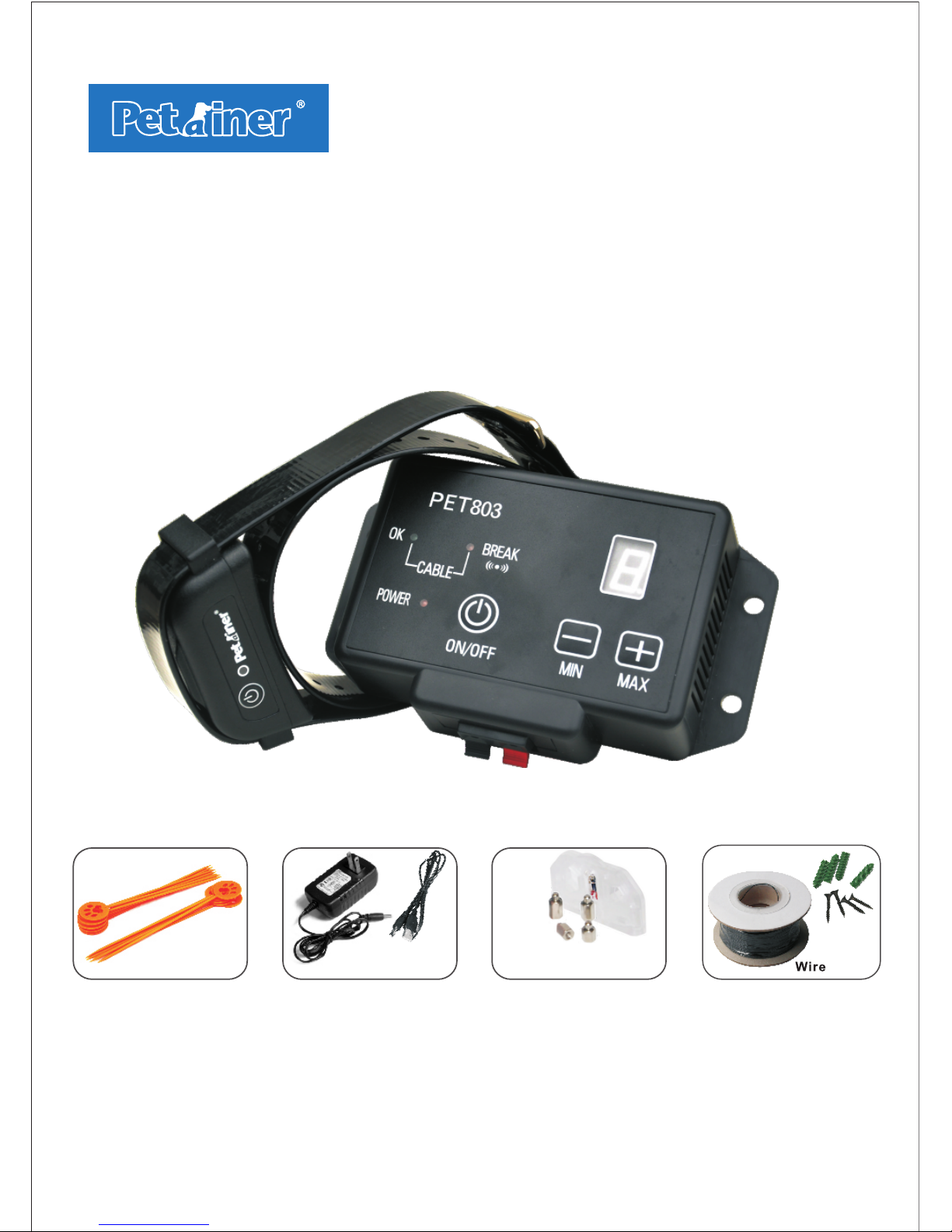
Electronic Pet Fence System
Boundary/
Trai ning Fl ags
Meta l Probe ls &
Test L ight To ol
Pet Fence System will make sure your dog stays safely in the yard.
Operating Guide
Please read this entire guide before beginning
&N ai ls
110- 240V
Adap ter
Page 2

Table of Contents
Main Features
2
3
3
Common size of different dogs
Common weight of dogs
3
4
4
4
18
18
Package Contents:
Other items you may need:
CAUTION
IMPORTANT NOTE
Operating Guide
INSTRUCTIONS FOR SETTING UP THIS FENCING SYSTEM
SECTION 1
SECTION 2 HOW THE CORRECTION WORKS
SECTION 3
TRAINING YOUR DOG
SECTION 4 SYSTEM MAINTENANCE TIPS
TROUBLESHOOTING GUIDELINES
SECTION 5
1
WARNING
Please charge the collar receiver before using the product!
If the receiver don t work for a long time, you should
charge it fully before keeping it idle, and charging it every
one month.
collar '
13
13
15
16
Page 3
Electronic Pet Fencing System PET803
This el e c t r o n i c p e t f e n cing sy s t e m
PET8 0 3 i s o n e o f t h e m o s t r e l i a b l e,
cost-efficient pet containment sy stem s
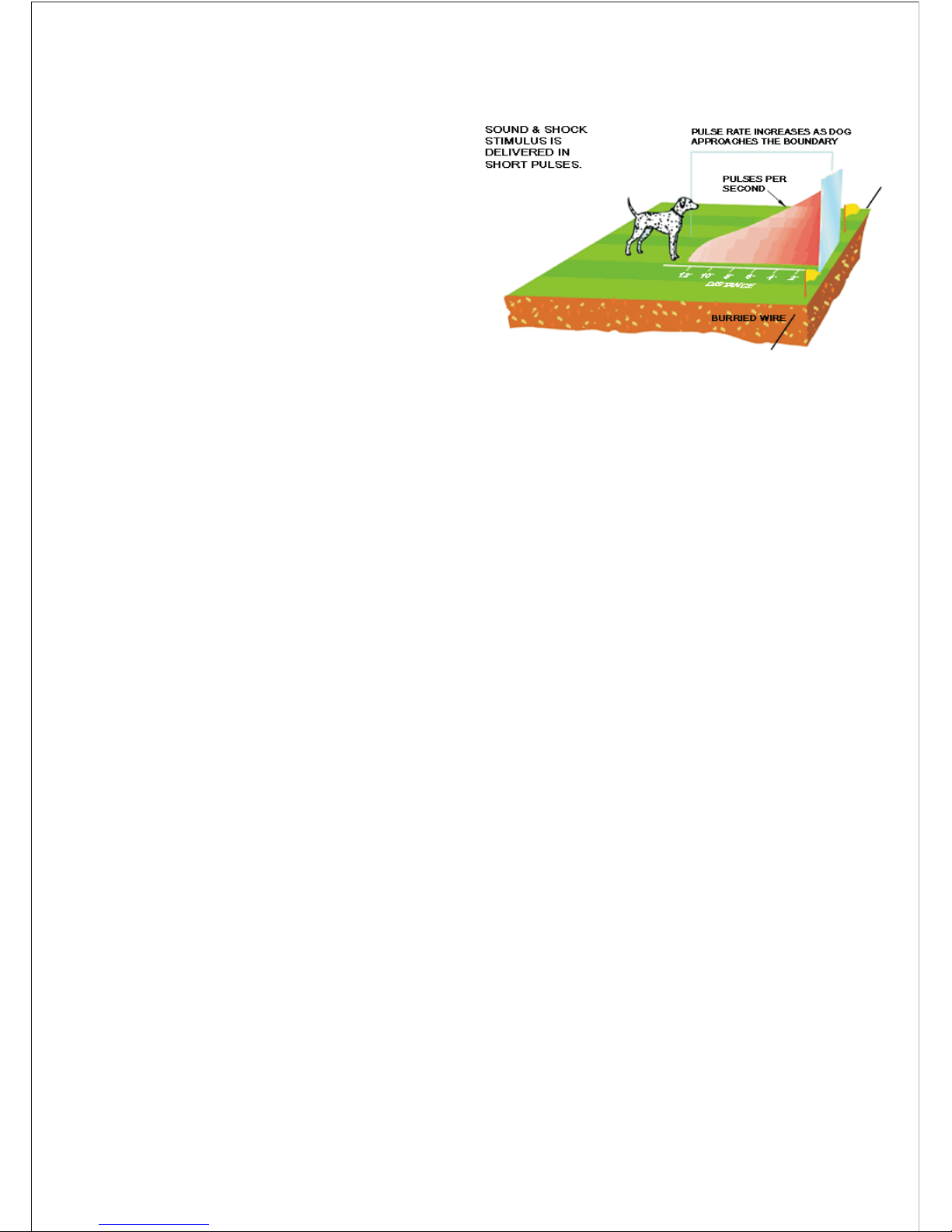
available today. A buried wire transmits
a harmless radio signal. When your dog
ap p ro a che s the bo un da ry, The si gnal
causes the dog's collar receiver to deliver
a warning beep first. If your dog continues
closer to the boundary, the sy stem will
issu e a m ild shock. If yo ur dog co ntin ues further, the s yste m will is sue stronger
shocks until your dog returns to within the boundary your have set up. Your dog will
na turally se ek to a void c or re ct io n an d i s co nt en tl y stay in g w it hin es ta bl is he d
boundaries.
Proportional static shock
The closer your dog gets to the boundary, the more intense the shock will be;
Progressive Warning Tone
A warning tone will be issued twice and then a shock stimulus if your dog continues
to move closer to the boundary;
Variable Field Width Control
Allows you to precisely control the width of the signal field;
Audible and Visual Wire Break Indicators
Should your buried wire ever break, a loud sonic alarm will so und accompanie d by
a flashing light;
Speed Detect Anti-Run through
The faster your dog is moving, and the higher level of intensity is issued;
Multiple Collar Operation
Add as many collars as you like to contain as many animals you have. The re is no
limit to the number of collars it can control.
Up to 2500 square meters range (over 0.62 acre).
Main Features:
2
Page 4

Package Contents:
1 x Indoor wall-mounted Transmitter;
1 x Power plug;
1 x Rechargeable and Waterproof Collar Receiver;
1 x Adjustable Collar
1 x AC Adaptor
2 x USB Charging Cable
1 x Boundary Wire of 200 Metres;
2 x Extra Metal Contact Points;
20 x Boundary/Training Flags;
1 x Test Light Tool
4 x Screws;
1 x User's Manual.
Other items you may need:
Screwdriver;
Straight edged spade or a lawn edger;
Wire stripping pliers;
Electrical tape;
Waterproofing compound (e.g. silicone caulk);
Patching compound for your type of driveway or sidewalk;
PVC pipe if crossing a gravel or dirt driveway, pond or lake;
Pencil, Ruler or Protractor;
Drill with drill bit or masonry bit if drilling through wood or concrete;
Additional Boundary Wire.
CAUTION
Please take a few minutes to read the instruction manual prior to your first use.
For best results, follow these important rules:
The electronic dog collar is intended only for use on dogs.
A low battery may cause intermittent operation. DO NOT USE if you suspect a
low battery.
Allo w your do g to get use d to the col lar before you begin training. You want
your dog to acce pt the co llar as p art of a ro ut in e, not to a ss oc ia te the collar
with correction.
DO NOT leave the collar on your dog for more than 12 hours per day.
3
Page 5

NEVER perform set-up procedures when the collar is on your dog.
An electronic collar should only be used under close supervision by the dog's
owner.
KEEP OUT OF THE REACH OF CHILDREN.
Read all instructions before using this product.
IMPORTANT NOTE
Realize that because individual dogs have unique temperaments, there is no way of
knowing how your dog will react to its introduction to this product. For the safety
of your dog, initial training should take place using a long leash to keep you in control
of the situat ion. Also rea lize that an agg ress ive animal co uld turn agai nst upon
receiving the stimulus. Therefore, if you feel your dog has an aggressive behaviour
and/or it has a history of aggressive behavior, you should consult a certified animal
behaviorist before using this product.
Step
1
SECTION 1
INSTRUCTIONS FOR SETTING UP THIS FENCING SYSTEM
PREPARE A LAYOUT OF YOUR CONTAINMENT AREA
A. Design and Draw Diagram
Prepare a diagram of the area you want to contain your dog.
location of house, driveway, pond, garden, swimming pool, etc. A diagram
will help to avoid unforeseen obstacles. If your neighbour has a containment
system installed, mark the location of the buried wire on your diagram.
Including the
B. Contact Utility Company
Contact your utility companies to mark any buried utility lines. Be sure to
include the buried lines on your dr awing beca use these uti lity li nes will
affect the placement of your wire.
C. Determine Location of Wall Transmitter
The transmitter can be mounted to a wall near any standard 110/240-Volt
ho usehold ou tl et wit h t he i nc lu de d scre ws . I t wi ll withstand fr eezing
temp erat ures, but it is no t water proof. Therefore, it is best to lo cate the
transmitter in an enclosed area. Inst all the t rans mitter at lea st three feet
away from any large metal objects such as breaker bo xes, w ater heaters,
metal garage doors, or washer and/or dryer. When installing the transmitter
4
Page 6
make sure the wire is not cut off or pinched by a window, door or garage
door. When drilling holes, make sure there are no electrical wires, nails or
screws inside the area you are drilling.
D. Det ermin e the Exi t Route of You r Bo u nd a ry Wi r e f ro m th e
Transmitter to the Outside Containment Area
Since your transmitter must be mounted in an enclosed are a to prot ect it
from the weather, give careful consideration on where the wire exits to the
exterior. Existing openings such as a window, door or utility line hole may
provide easy access to the outside. You may need to drill a hole through the
exterior wall.
Step
2
ADD PROPOSED WIRE LOCATION TO YOUR
DRAWING
Mark your dia gram with the pr oposed loc atio n of your wi re. This w ill
provide an easy reference as you install the wire. For t he system to work
properly, the wire must make one continuous loop. The signal is transmitted
from one term inal of t he transmitter, thro ugh the wire and b ack to th e
other terminal.
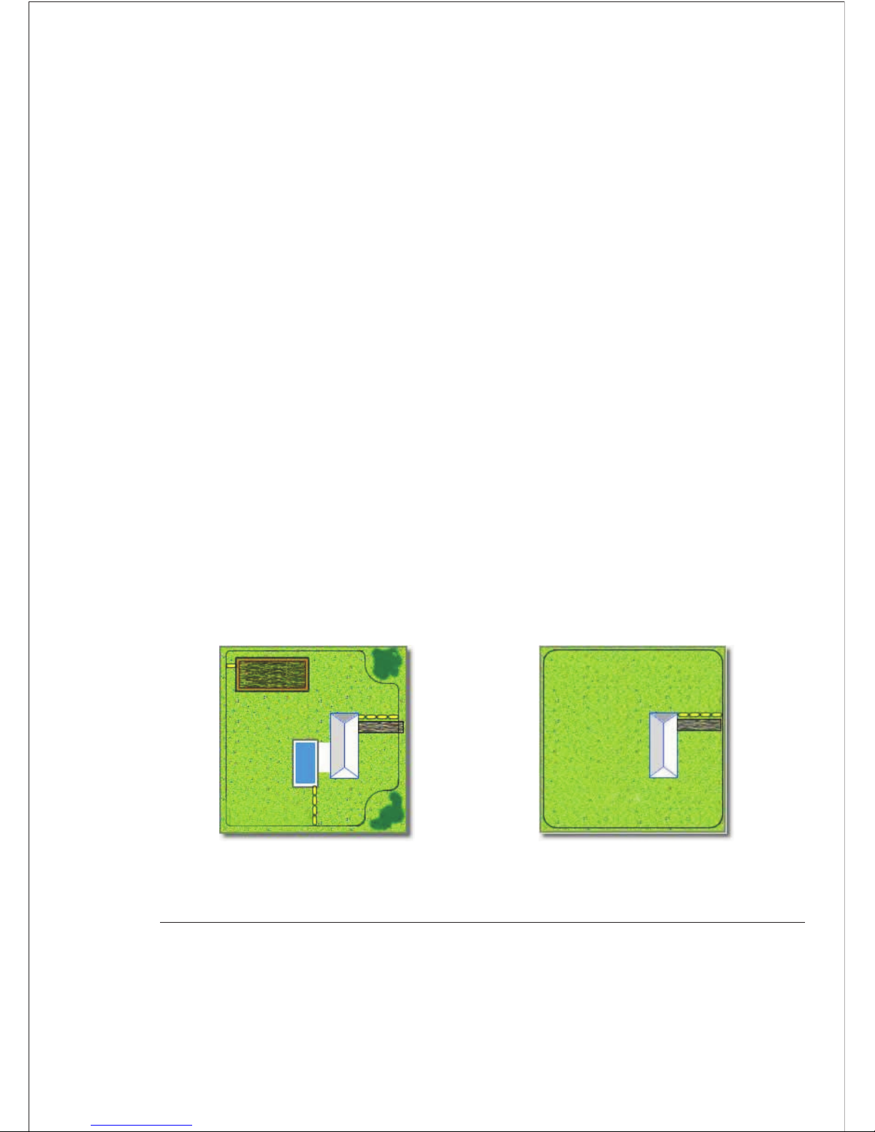
Example Installation Diagrams
Zones within Zones
Basic Single Wire Zone
Keeps your pet safely away from
gardens, pools, and other areas.
Your pet has a 360 degree perimeter
to roam within.
5
Page 7
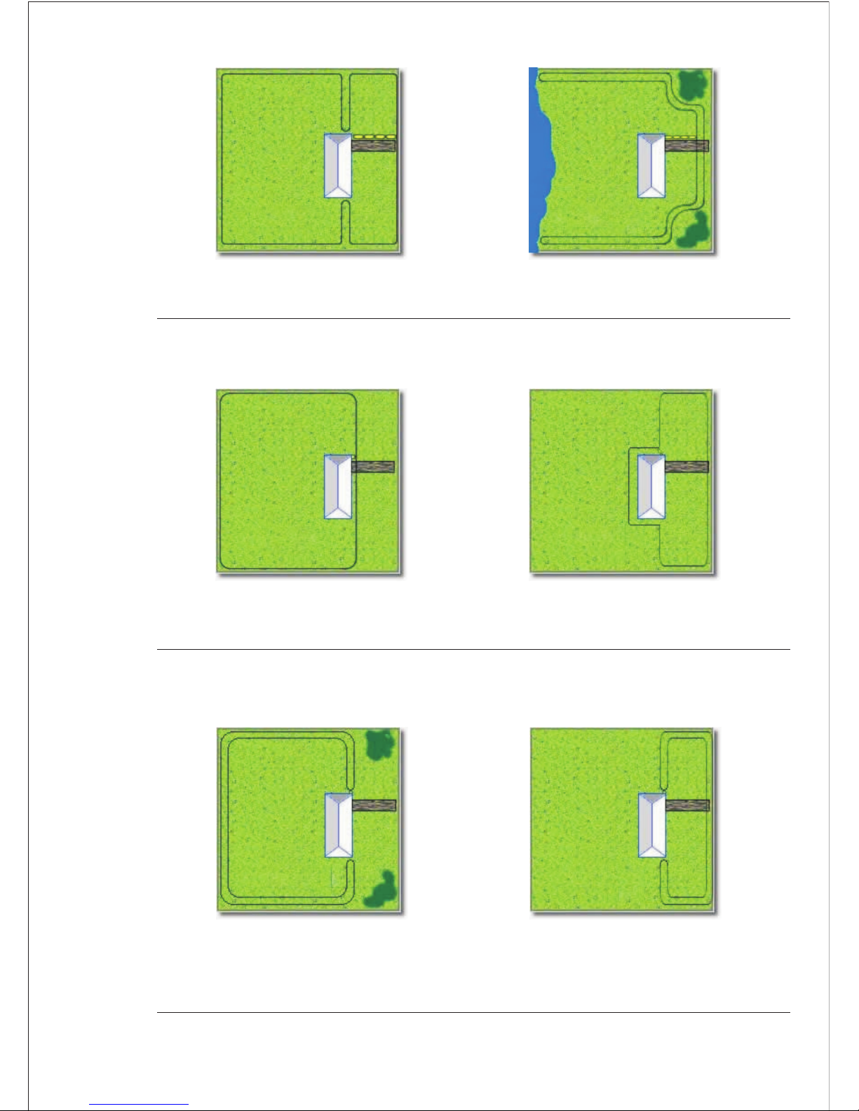
Your pet has run of the house and
back yard.
Your pet has run of the house and
front yard.
Dual Zones
Open Back Zone
Keep pets separated, or to prevent
run-thru.
This lets your pet have access to the
lake or other rear area.
Single loop - Back Yard Zone Single Loop - Front Yard Zone
Double Loop - Back Yard Zone
Double Loop - Front Yard Zone
Your pet has run of the house and
back yard.
Your pet has run of the house and
front yard.
6
Page 8
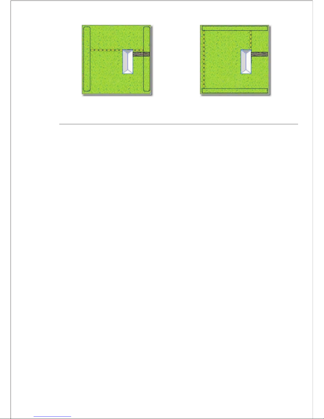
Front & Rear Barrier Zones
Side Barrier Zones
Your pet has full access to both
sides, but not to the front or rear.
Your pet has full access to the front
or rear, but not to the sides.
Step
3
IMPORTANT NOTES FOR WIRE PLACEMENT:
Do NOT run the wire less than 15 metres under any occasions. Do NOT
run the level of the signal field to maximum "H" when the wire is just over
15 metres, otherwise it will burn the wall transmitter (level 5 of field is
maximum). Wire MUST be over 100 metres if you need to use the level "H"
of the signal field. If required wire is shorter than 100 metres, it will be
safer to run double or even triple loop to make the layout wire over 10 0
metres.
Do NOT run th e loop within 2 meters pa rall el to electrical, telephone,
cable TV, or other buried wire in the yard.
Do NOT run one section of wire within 3 meters of another section or the
signal may cancel.
Do N OT r un you r w ir e wi th in 3 me te rs of a ny a dj ac en t c on t ain m en t
system's wire.
Do NOT run yo ur wire w ithi n 3 c enti -meters o f an y ste el s b ar s un de r
concrete ground otherwise signal strength will be reduced.
'' ''
ESTIMATE THE AMOUNT OF WIRE NEEDED
PET803 model includes 200 metres of boundary wire. It c an enclose an
area of over 0.8 acres.
The amount of wire needed is determined by several factors:
(a)Total area to be contained;
(b)Using a double loop. This requires twice as much wire.
7
Page 9
(c)Size of the signal field. The signal field is the distance from the wire
to the place where the collar receiver first activates. A 3 to 4 meters wide
field is preferred.
Step
4
INSTALL THE WALL TRANSMITTER
Install the wall transmitter close to a standard 110/24 0-Volt househol d
outlet. Do not plug the transmitter to the outlet until the boundary wire is
in place.
IMPORTANT NOTE:
We recommend that you unplug the transmitter and d isco nnect the fen ce
wire during lightning storms.
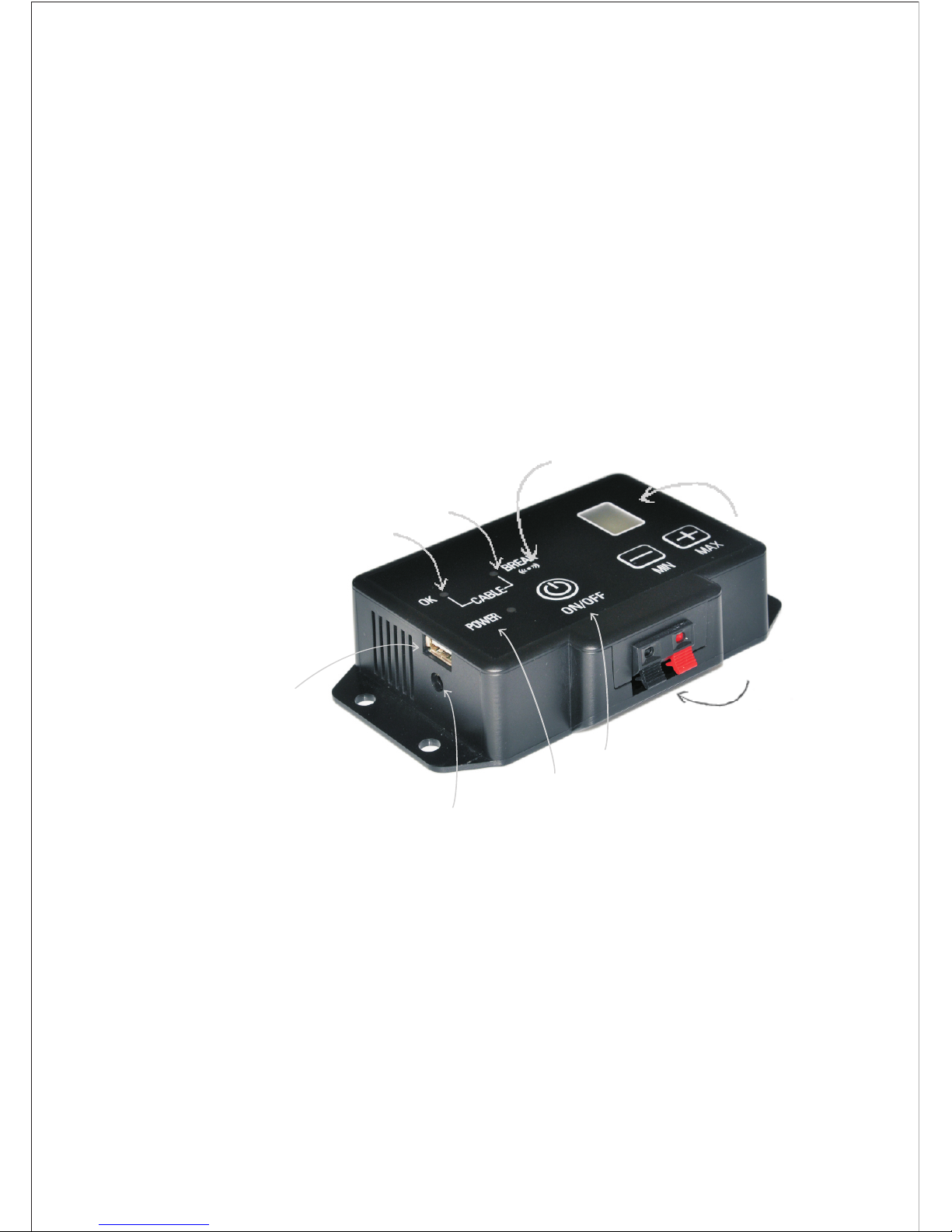
Cable OK
Calbe Break
Power Port for Transmitter
Wire teminals
ON/OFF field width
adjust ment knob
If underground wire break, aloud
sonic alarm will sound
The Signal
Field Width
Power Light
LAY OUT THE PERIMETER WIRE
IMPO RTANT NOT E: Do NOT bur y the wire until you have t es te d th e
syst em and ar e sure it is wo rking prop erly. D o NOT nick or scrape the
wire during installation. Improper function may result.
1. Use your drawi ng as a reference. Be gi n laying th e wi re around t he
perimeter of your containment area to form a continuous loop. Use gradual
turns at the corners with a minimum of 1meter radius. This provides a more
consistent signal field.
2. If you are using mo re wire than ini tial ly supplie d with your fenc ing
Step
5
8
Charging Port
for Collar Receiver
Page 10

syst em, the w ire connec tion s must be wa te rp ro of t o p ro vi de a sealed
connection between the wires. Do not use electrical tape or twisted wire
nuts. This will cause an intermittent signal or disarm the system.
3. Continue around your perimeter until you return to the start of the loop.
4. Cut the wire.
Step
6
CONNECT T H E PERIM E T E R WI R E T O T HE W A LL
TRANSMITTER
The wire from the perimeter to the wall transmitter should be twisted to
cancel the signal. This allows the dog to cross the area without receiving
a correction. It also eliminates possible interference from electrical wires,
etc.
1. Mea su re the di st an ce f ro m t he w al l t ran s mi t ter to t h e e d ge o f th e
perimeter wire.
2. Because twisting the wire decreases the length of the wire, multiply the
distance by 1 .
3. Measure and cut two wires of equal lengths of the above measurement.
4. Hold the two ends of the wire side by side and twist them together. The
wires can be twisted manually until the twists are 6 to 12 cm apart. The
tighter the wire is twisted the better the signal cancellation.
5. Pull the twisted wire to the perimeter location of the two ends of your
boundary wire loop. Splice the ends of the twisted wire to th e ends of
the boundary wire ONLY with waterproof splices.
6. Put the twisted wires through the existing opening or drilled hole so it
can be connected to the transmitter.
7. Strip off about 1 cm of insulation from the end of each twisted wire.
8. Insert the wires into the terminals of the transmitter.
9. Plug the power adapter into a standard 240-volt household outlet.
10. Connect the power adapter to the transmitter's power port.
Step
7
VERIFY TRANSMITTER IS FUNCTIONING PROPERLY
To verify the transmitter is functioning properly, look for OK and Power
lights on the transmitter. When the OK turn s green a nd the Power lig ht
turn s red, it me ans the t ransmitter is r ec ei ving p ow er, b o th w ire s ar e
9
Page 11
connected, and the wire
light turns red, it means that one or both wires are not properly connected
or both wires are connected but the wire is broken. Co rrec t the pro blem
and retest.
forms an unbroken, continuous loop. If the Break
SET UP YOUR COLLAR RECEIVER
Before using our Rechargeable and Waterproof Collar Receiver, for the
first use, please make sure charging it at least 4 hours.
Turn on the power button on the receiver and the red LED light will turn
on. When the indicator light turns flashing red, it means battery is running
down and needs to be recharged.
Step
8
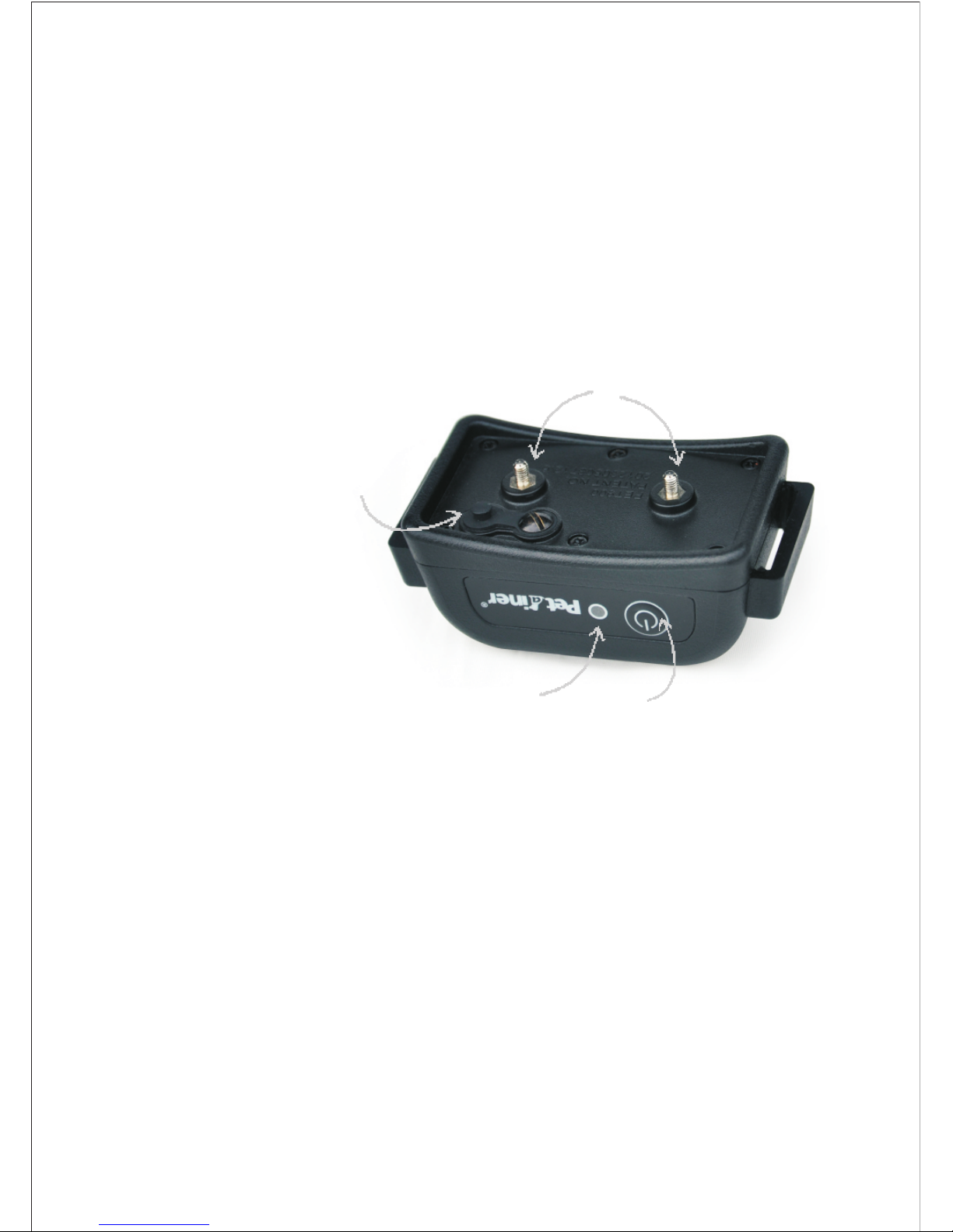
ON/OFF Button
Charging Jack
and Rubber Cover
LED Indication Light
Contact Points
IMPORTANT NOTE:
Do NOT place the collar receiver on your dog until the fencing system has
been tested and the signal field adjusted.
Step
9
TEST THE FENCING SYSTEM
Do Not Test The Fencing System with The Collar Receiver On The Dog.
You must manually test the containment system to verify that the signal
is properly transmitted through the wire. Use the supplied test light.
Sele ct a sect ion of straig ht boundary w ire that is at least 50 feet l ong.
Attach the supplied test light to the receiver p robe s and hol d the collar
rece iver at y our dog's nec k height. Slo wly walk the co ll ar tow ar d t he
boundary wire. Listen for the warning tone and watch for the test light to
light. The wider you can make the Fencing field, the less chance your dog
can run through. Adjust the FIELD WIDTH as necessary and test again.
10
Page 12

Test in a number of different areas until you are satisfied there are no wire
breaks and the system is functioning properly.
Next walk all around the part of the yard to ensure there are no stray
signals, particularly near the twisted wire coming from the transmitter.
Test collar in and arou nd the inside of the hous e as well. Signa ls from
Cable TV, electrical or telephone lines can "couple" causing stray signals
inside and outside the house that can activate the dog's collar accidentally.
If you do encounter this phenomenon, your boundary wire is probably too
cl ose to these ou tside lin e s a n d wi ll n e ed t o b e mo v ed o r mo d if i ed.
Containment collars should not be worn inside the house.
"safe"
ADJUST THE SIGNAL FIELD WIDTH
The signal field is the distance from the wire to the place where the collar
receiver first activates. The "+" "-" button on the transmitter adjusts th e
size of the signal field, not the correction intensity. Pushing the "+" button
increases the signal field width; Pushing "-" button decreases it. Pushing
ON/OFF button to turn on/off the transmitter power.
Follow the instructions in Step 10 to test the signal field width. Walk th e
entire perimeter to be sure that the signal field is consistent throughout
your containment area. The signal field should ex tend a minimu m o f 2
meters on either side of the wire (creating a 4 meter wide field). A 3 to 4
meter wide field is preferred. The wider the sign al field widt h, the less
chance that a dog can run through the field.
Step
10
INSTALL THE BOUNDARY WIRE
Tools Needed
Straight-edged spade, wire cutter / stripper, and standard screwdriver. If
you plan to run the wire across concrete, you will also need a caulk gun,
silicone caulking, and a circular saw with a masonry blade.
Burying the Wire
The wire does not have to be buried, but for protection you probably want
to bury it at least one inch underground. Start by digging about 7 to 10cm
deep where the wire first enters the ground near the transmitter and continue
around the path of the loop wire.
Note:
When covering a large area, you may wish to use a trenching machine to
cut into the ground. However, we recommend that the wire be placed in the
trench by hand. A commercial wire-placing machine may break the wire.
Step
11
11
Page 13

Driveways / Sidewalks
Wh en c ro ss in g an as ph al t dr iv ew ay make a 2cm deep c u t a c ros s th e
driveway using a circular saw and masonry blade. P lace th e wire in th e
crack and seal with asphalt sealant. On driveways a nd sid ew al ks , if an
expansion joint is available, simply place the wire i n the jo in t an d s ea l
with an outdoor caulk. When crossing gravel, bury the wire at least 7 cm
deep. Use an old garden hose or plastic PVC piping to protect the wire. In
water, anchor the wire with large rocks. Protect the wire with an old garden
hose or plastic PVC piping.
INSTALL THE BOUNDARY TRAINING FLAGS
After installing the wire, retest the fencing system as described in Step 10,
Verify that the signal field width is consistent by following the instructions
in Step 11. Adjust the Signal Field Width. As you are retesting and verifying
the system, install the boundary training flags. Place the flags wh ere th e
warning tone is first heard as you approach the wire. The fl ags should b e
placed at the edge of the signal field width, not directly on t he wire. T his
will add a visual cue to the audio warning tone and help your dog to learn
the boundary.
Step
12
Step
13
FITTING THE COLLAR TO YOUR DOG
IMPORTANT NOTE:
Never leave the collar receiver on the dog for longer than 12 hours a day.
Leaving the collar on the dog for ex tend ed periods co uld result in sk in
irritation. Check your dog's neck periodically for skin irritation.
A. Probes
Make sure both probes contact the dog's skin. If needed, a small amount
of hair removal or thinning will improve probe contact with the skin.
Use short probes for short-haired dogs. Use long probes for long-haired
dogs.
Finger-tighten the probes then turn them one a dditional revo luti on. Do
not over-tighten.
12
Check the tightness of the probes regularly to prevent loss of the receiver
box.
Page 14

B. Collar Strap
To prevent accidental correction inside the home, remove the collar from
the dog's neck when it comes inside.
Place the collar around the dog's neck with the receiver box under the chin.
The collar mu st be on rel ativ ely tight to kee p the pr ob es m ak in g s ki n
contact without restricting breathing. You should be able to slide only one
finger under the strap at the back of the dog's neck.
Always make sure the collar is functioning properly BEFORE putting it
on the dog.
Remove other metal collars when the dog wears the containment collar.
Metal collars may interfere with proper operation.
Remove the collar and trim the excess strap
SECTION 2
HOW THE CORRECTION WORKS
1. Pre-Correction Warning Tone:
When the dog reaches the edge of the signal field in the yard, it will hear a warning
tone that lasts about 10 seconds. If the dog does not return to the safe part of the yard,
it will receive two static shocks every a warning tone until it returns to the safe area.
Within 20 seconds, if the dog reaches the edge of the signal field in the yard again, a
warning tone plus static shock will be activated.
2. Run-Through Prevention:
The receiver automatically increases the correction as the dog enters the signal field.
A four warning tone along with 4 correction shocks and a six warning tone along with
5 correction shocks will be activated as the dog move closer and closer to the wire.
The dog cannot "run through" the signal field without receiving a strong correction.
SECTION 3
TRAINING YOUR DOG
To get the most out of your fencing system when training, keep these tips in the mind:
To prevent accidental correction inside the home, remove the collar from
the dog's neck when it comes inside.
13
Page 15

Always make sure the collar is functioning properly BEFORE putting it on
th e do g. Ver if y the s ys te m is op er at in g pr op er ly and the fi eld width is
appropriate as described in Section 1, Step 11. Adjust the Signal Field Width.
Stay positive and playful during the training session.
Keep training sessions brief. Never continue a session after your dog has
lost interest. Take a break to rest or play.
ALWAYS praise your dog for good behaviour.
The following steps outline a successful training plan:
Step
1
FLAG TRAINING
1. Turn the wall transmitter so no corrections will be given to your
dog.
"off"
2. Place the collar receiver on your dog.
3. Place a long leash on your dog. Play with your dog in the saf e area of
the yard for 2-4 minutes. Do not allow your dog to run free or cross the
flag lines.
4. Walk towards the flags. Reach down and shake a flag. Say "bad flag"
a disapproving tone.
in
5. Return to the centre part of the yard and play with y ou r dog. Re ward
with treats.
6. Repeat this exercise several times in various locations of the yard.
Step
2
1. You need to reset the signal field width before placing the collar receiver
on your d og. Follow th e instructions ou tlined in Sec tion 1, S tep 11,
adjust the Signal Field Width.
2. Place the collar receiver on your dog in the safe area of the yard.
3. Place a long leash on your dog. Play with the dog in the safe area of the
yard.
4. Walk towards the flags. If your dog tries to avoid the flags, praise and
reassure your dog.
5. Repeat this step in other locations of the yard.
6. Allow no more than three corrections in a day or seven in a week. This
depends on your dog's stress tolerance. Most dogs o nly receive a few
corrections during the training phase; they respond to tone very quickly.
THE FIRST CORRECTION
14
Page 16

7. Reward your dog when it avoids the flags, even if a correction is issued.
8. Play in the safe zone with your dog before ending this training session.
1. With th e collar on your dog and the wall tra nsmi tter , play with
your dog (on leash) in the safe area. After a few minutes of play, toss a
toy or treat through the flags.
"on"
2. If your dog runs through the flags to chase the toy, wait for the startled
response and pull your dog back into the safe area. Praise and reward
your dog.
3. Reinforce training by shaking a flag. Say "bad flag" with a disapproving
tone. Consider increasing the signal field area. If you choose to increase
the signal field area, remove the collar from your dog, increase the signal
field, and retest. Refer to Section 1, Step 11, Adjust the Signal Field.
4. Repeat this exercise in other locations of the yard.
5. Pra is e y ou r do g when it avo id s t he f la gs . St ay positive a nd playful
during the training session.
6. When your dog refuses to run through the flags 20 consecutive times,
proceed to the next step.
ON-LEASH PROOFING
Step
3
Step
4
OFF-LEASH PROOFING
1. Follow the instructions in Step 3, On-Leash Proofing except drop the
leash on the ground. It will be available if you need to retrieve your dog.
2. If your dog gets through the signal field during this phase, quickly
remove the collar. Bring your dog back into the safe area. Put the collar
back on your dog. Reinforce "bad flag" training. Praise and reward
your dog.
3. Repeat this off-leash training until you are confident that your dog will
ignore temptations outside the containment area.
SECTION 4
SYSTEM MAINTENANCE TIPS
Your system requires very little maintenance. The rechargeable collar receiv er is
waterproof.
15
Page 17

The wall transmitter is not waterproof and must be protected f rom the w eath er. A
close lightning strike may damage the unit. Unplug the transmitter a nd disconnect
the wires during storms.
Do not attempt to dismantle or repair any of the system components; this will void
the manufacturer's warranty.
Test the system once a week to make sure the collar receiver is wor king properly.
Also, testing the system will verify the field width setting is correct. To test, attach
the supplied test light to the collar receiver probes. Holding the receiver by the case,
NOT by the probes, walk into the signal field. Listen for the war ning tone to sou nd
and the test light to illuminate.
TROUBLESHOOTING GUIDELINES
SECTION 5
A.Dog is not responding to correction:
Adjust the collar fit.
Trim the dog's hair or use longer probes to make better skin contact.
Charge the collar receiver.
B.System Test Procedure:
Whenever you experience a malfunction, you will need to do a Test Lo op
to determine which component - collar, wall transmitter, or yard wire - is
not working. To perform the Test Loop procedure:
1. Make a test loop using a piece of wire at least 4 meters in length.
2. Remove the existing wire from your wall transmitter.
3. Insert the two ends of the test loop wire into the wall transmitter.
4. Set the field width level to a low setting.
5. Place the test light on the collar receiver. With the collar in hand, move
outside the field and approach the test loop. Make a mental note of the
distance between the collar and the wire when the collar activates.
6. Set the field width level to a medium setting.
7. Back away from the wire and approach it again. Determine the dis tanc e
between the collar and the wire when the collar activates. The distance
should be greater on the medium range setting.
8. If more than one collar receiver is used with the system, repeat the above
test on each collar.
16
Page 18
Results of System Test Procedures:
If there is no red PO WER lig ht on the wall transmi tter with the te st loop w ire in
place, the wall transmitter is malfunctioning.
If the red POWER and gree n OK lights are solid on the w all transmitter, b ut the
collar does not activate on the test loop wire, the collar receiver is not working. Charge
the collar receiver and repeat the test.
If the red Break light on the transmitter turns on together with beeping sound, the
problem is in the yard wire.
Warning:
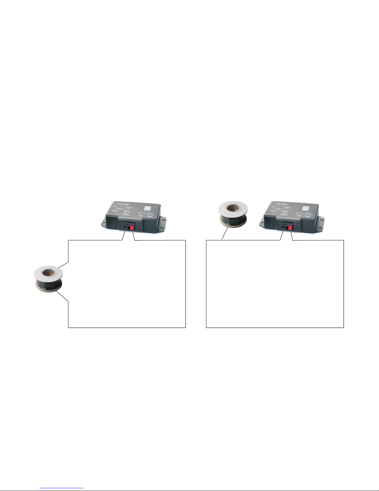
1. The system included a boundary wire of 200 metres. If there still have wires after
you used it to make the fence wire. Please cut down the unused wire. You can't use
the remanent wire to connect with the transmitter. O ther wise t he transmitter wi ll
can't working properly.
(This connect way is wrong)
2. If there are any wrong operation caused the system w orking unc onve ntio nally.
Please unplug the power of the transmitter. After 5minutes, The system will work
properly when you plug the power again.
(This connect way is right)
17
Page 19
18
Common size of different dogs
Size
Neck
(cm)
Back
Length
(cm)
Type
Mini
Small
Medium
Large
Large
Large
Huge
20-22
20-24
23-28
27-31
30-34
33-37
43-48
47-52
52-62
25-30
29-36
35-42
41-47
46-53
52-59
76-84
88-97
92-100
19
23
28
31
35
40
60
65
70
Chest
Measurement
(cm)
Chihuahua, Yorkshire
Temier
Chihuahua, Yorkshire
Temier, Poodle, Pomeranian
Maltese Dog, Shih Tzu
Miniature Schnauzer,
Pekingese
Beagle
Husky
Labrador Retriever
Golden Retriever, Old
English Sheepdog
Schnauzer, English Cocker
Spaniel
Common weight of dogs
Large Dog (Body height above 61cm, Weight above 40kg)
Medium Dog (Height 40.7-61cm, Weight 11-30kg)
Small Dog (Height 25.5-40.7cm, Weight 4-10kg)
Mini Dog (height under 25cm, Weight under 4kg)
Page 20

 Loading...