

Page 1
Part No. 81-9059-0732-0 Rev. A
Quick-Start Guide
C22
For further information, refer to PESA Xstream C22 User Guide
Carefully unpack C22 module from shipping container and verify
package contents against contents shown below
Visually inspect for any signs of damage in shipment or transit
If any components are missing or damaged, contact PESA
Customer Service
1
2
P
ACKAGE CONTENTS
:
V
ERIFY ITEMS SHOWN ABOVE ARE INCLUDED WITH MODULE
*
U
NPACK
S
HIPPING
C
ONTAINER
1
Step
U
NPACK XSTREAM
C22
M
ODULE
2
Step
GET A
CQUAINTED
2
Step
GET A
CQUAINTED(CONT
.)
Quick
Start
Guide
AC POWER ADAPTER –
IF PURCHASED AS
STAND-ALONE
MODULE
PESA’s X
STREAM
C22 is a dual channel encoder/decoder
device for high definition video processing, audio processing
and IP streaming.
Each processing channel supports an IP streaming decoder
that functions as a remote client for decoding an IP stream for
video streams up to 720p/60, and an IP streaming encoder to
broadcast an IP output stream from a variety of input signal
sources.
Each processing channel offers video and audio input and
output interface through a variety of rear panel connection
options and signal formats at resolutions up to 1080p/60.
BNC ports and SFP connector ports are bi-directional.
Input for an external analog sync reference source allows local
output video to be frame synced for use in broadcast and other
high-end video environments.
An independent audio mixer function is provided for each
encoder and local output allowing audio associated with each
input or output video source to be blended or replaced with
local auxiliary audio.
All audio processing is dual channel for full L/R stereo or other
applications.
C22 is housed in a small footprint, modular chassis.
Front panel display device and channel status LEDs provide
real-time status monitoring.
Optional rack mount kit allows up to two C22 modules to be
installed in a single 1 RU frame with a built-in power
distribution module that provides power for both modules.
Integrated web server supports a browser-based graphical
user interface (GUI) control application for password-protected
access to all operating controls and functions of the device.
F
RONT AND REAR PANEL LAYOUT
The following support equipment is recommended for best performance of a C22 installation:
- Gig-E Ethernet Recommended, 100 Mbps Minimum
- Recommended Web Browsers:
Google Chrome, Ver. 36.0 or later
Mozilla Firefox, Ver. 24.0 or later
Apple Safari, Ver. 6.2 or later
Internet Explorer, Ver. 10.0 or later
PESA’s Xstream C22 ships from the factory with the following factory defaults:
IP Address: 192.168.1.100
Gateway: 192.168.1.1
Subnet Mask : 255.255.255.0
Bi-directional rear panel BNC connectors by default are selected as input ports.
S
YSTEM REQUIREMENTS
F
ACTORY DEFAULTS
Locate each C22 module or extender frame for convenient access to I/O signals and Ethernet
network connection.
Ensure primary power is available and that each module or extender frame has clearance for
cooling air.
If mounting modules in extender frame, slide module into position from rear, as shown below,
and secure by tightening thumb screw on front of rack panel.
When modules are mounted in extender frame, power is derived from external power supply(s)
and connected to individual modules using connector cables from power distribution module as
shown.
For further information, refer to PESA Xstream C22 User Guide
4
Step
C
ONNECT VIDEO
& A
UDIO
I/O
AND
N
ETWORK CABLES TO
C22
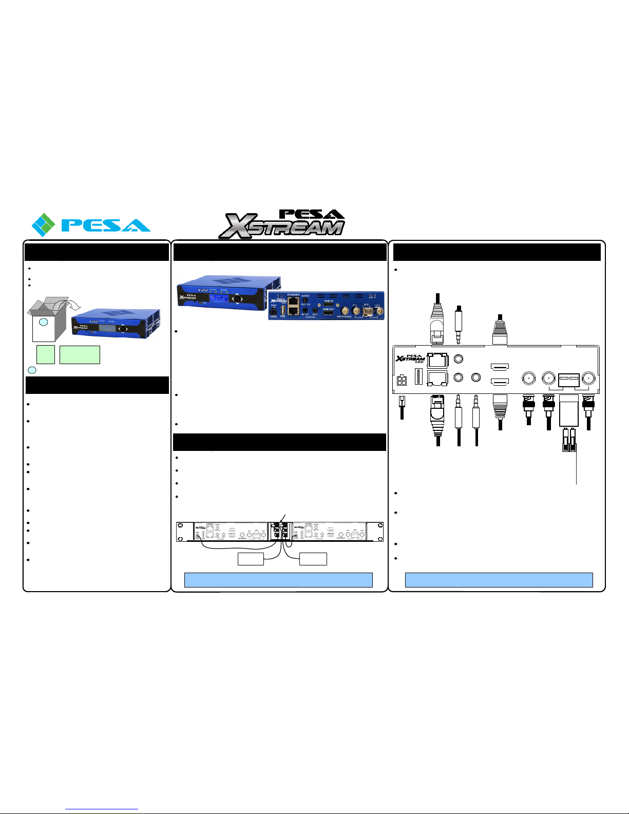
Using illustrations below and in Step 2 for reference, complete I/O connections to module prior
to applying power.
Power (PWR) - Operating power (12 VDC) is attached to this connector. When module is used
standalone, power is derived from a furnished external power supply “brick.” If module is
mounted in rack frame, power is derived from frame power distribution module.
Ethernet Ports 1 and 2 – PESA XStream C22 has a 2 port Ethernet switch built-in. You may
use either RJ-45 port to connect the C22 to the Ethernet, and use the open connector as a
connection point for another device. Often, this feature is used to daisy-chain C22 modules. Be
aware, however, that if the directly connected module is removed or loses power, the
downstream device will also lose connection to the Ethernet.
Audio In 1 & 2 (3.5mm TRS Connectors) – Dual inputs for stereo analog audio signals. See
example hook-up illustrations and pinout table on next page.
Audio Out 1/2 (3.5mm TRS Connector) – Dual line level, stereo, analog output audio signals
for program or monitoring applications. See pinout table on next page.
PWR
ETHERNET
AUDIO
OUT 1/2
IN 1/2*
IN 2*
USB
+12VDC
HDMI IN
HDMI OUT
*See User Guide
REFERENCE
I/O 1
I/O 2
SFP
1 2
SFP
I/O
Module
+12 VDC Primary Power
From External Power
Module or Rack Mount
Chassis Power Supply
Ethernet
Network
Port 2
Ethernet
Network
Port 1
Analog
Audio Input*
Channel 1 & 2
(L & R) with
Unbalanced
Inputs
Channel 1 (L)
with Balanced
Input
Analog
Audio Input*
Channel 2 (R)
with Balanced
Inputs
Not Used with
Unbalanced
Inputs
*See Table in Next Column
Channel 1 &
2 (L & R)
Unbalanced
Outputs
Analog Audio
Output*
Native HDMI Input
Selectable as
Source Signal for
Either Processing
Channel 1 or 2
May attach a DVI
Input with Adapter
Cable
HDMI Input
HDMI Output
Local HDMI
Output
May attach a
DVI Adapter
Cable
Analog
SYNC
Reference
Input
Processing
Channel 1
Bi-Directional
BNC I/O
Connector for
SDI Video
Select Port Signal
Direction through
Webcenter
Control Page
Processing
Channel 2
Bi-Directional
BNC I/O
Connector for
SDI Video
Select Port
Signal Direction
through
Webcenter
Control Page
Chnl 1
I/O
Chnl 2
I/O
Bi-Directional SFP
Module Cage
Supports SFP I/O
Module for Specific
Application
(See User Guide)
3
Step
L
OCATE
C22 M
ODULE IN OPERATING POSITION
OR INSTALL IN OPTIONAL RACK FRAME
Power Distribution / Fan Module
External Power
Supply Module A
External Power
Supply Module B
(Redundant Power)
Page 2
Step
S
YSTEM SET-UP AN D CONFIGURATION
If not already powered-up from previous step, apply power to C22 and allow it to
complete boot-up sequence.
Open a web browser on a network connected PC and enter the IP address of the C22
in the browser URL address bar.
NOTE: Currently set IP address of C22 module is shown by the front panel display
The login screen as shown here should open.
If the login screen does not open, or you receive a communication error message,
open a command entry window from the Windows Start button and ping the default IP
address.
If the ping is successful, try using a different web browser.
If the ping is not successful, consult your facility IT administrator for possible network
conflicts.
6
Step
M
ODIFY
C22 N
ETWORK COMMUNICATION
P
ARAMETERS
If you do not need to modify the C22 network communication parameters, continue to
Step 7.
Open the C22 webcenter control application to the login screen. Refer to Step 5.
Login to webcenter using the default administrator account with the following
credentials:
Username – admin
Password – a
Select the System button from the landing page as shown here.
5
Step
E
STABLISH CONNECTION TO
C22 W
EBCENTER
C
ONTROL APPLICATION(CONT
.)
Part No. 81-9059-0732-0 Rev. A
Quick-Start Guide
C22
For further information, refer to PESA Xstream C22 User Guide
C
ONTINUED ON NEXT PAGE
HDMI In – Native HDMI input port. May attach a DVI input signal with an adapter
cable. Input signal at this connector may be selected as a source signal for either
processing channel.
HDMI Out – HDMI output port. May attach a DVI input signal with an adapter
cable. Output signal at this connector may be selected through software as the
local output of processing channel 1 or 2.
Reference – Accepts an input of analog video sync reference from an external
source, such as tri-level sync.
I/O 1 and 2 – These BNC connectors provide a bi-directional video interface for
SMPTE SDI video with embedded audio. Through control software, either BNC
may be configured as a video input port or output port for its respective
processing channel, 1 or 2. By default, each BNC is configured as an input port.
SFP – Dual channel mounting cage for installation of a variety of SFP input or
output modules. Both SFP channels may function as an input port or output port,
depending on the SFP module installed.
4
Step
C
ONNECT VIDEO
& A
UDIO
I/O
AND
N
ETWORK CABLES TO
C22 (C
ONT
.)
PWR
ETHERNET
AUDIO
OUT 1/2
IN 1/2*
IN 2*
USB
+12VDC
*See User Guide
4
Step
C
ONNECT VIDEO
& A
UDIO
I/O
AND
N
ETWORK CABLES TO
C22 (C
ONT
.)
3.5mm Male to
Male Cable
Direct Connection to
Unbalanced PC
Audio Output
IN 2 Not
Used in This
Application
E
XAMPLE
- U
NBALANCED AUDIO FROM
PC
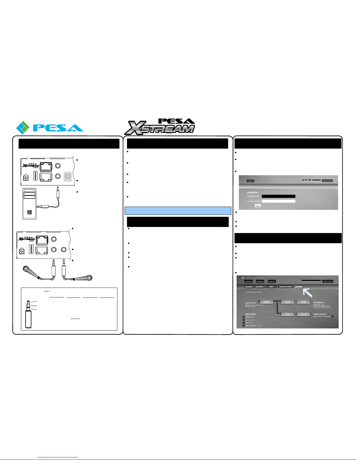
When connecting unbalanced
input audio sources to C22,
such as the output from a
computer, both channels are
attached through the IN 1/2
3.5mm connector.
Pinouts for C22 input and a PC
sound card output are pin-forpin compatible.
IN 2 connector is not used
when attaching unbalanced
inputs.
E
XAMPLE
- B
ALANCED AUDIO FROM EXTERNAL MICROPHONES
Tip
Ring
Sleeve
Chnl 1 (L) +
Chnl 2 (R) +
Common
Ground -
Chnl 1 (L) +
Chnl 1 (L) -
Channel 1
Shield
IN 1/2
Unbalanced
Inputs
IN 1/2
Balanced
Inputs
IN 2
Balanced
Inputs
Chnl 2 (R) +
Chnl 2 (R) -
Channel 2
Shield
*Analog Audio Input & Output Pinouts
NOTES
Connector IN 2 Not Used when Attaching Unbalanced Inputs
Analog Audio Outputs are Unbalanced Only
Phantom Power Available Only with Balanced Inputs
Chnl 1 (L) +
Chnl 2 (R) +
Common
Ground -
OUT 1/2
Unbalanced
Outputs
Connector
When connecting balanced input
audio sources to C22, such as from a
microphone with XLR connector,
each channel is attached through one
of the 3.5mm connectors. See pinout
table at bottom of this column.
Inputs may be line level or
microphone level. C22 auto-detects
input level of source.
Phantom power for condenser
microphones may be switched to
both inputs through webcenter
configuration page.
PWR
ETHERNET
AUDIO
OUT 1/2
IN 1/2*
IN 2*
USB
+12VDC
*See User Guide
C22 factory default network communication parameters are:
IP Address 192.168.1.100
Subnet Mask 255.255.255.0
Gateway 192.168.1.1
Verify that the factory default parameters are compatible with your facility network,
and that the default IP address will not cause a network conflict before applying
power to C22.
Verify that the C22 Ethernet port is connected to the facility network.
Once you have established network communication with C22, you may change
the operating network communication parameters of the device for network
compatibility through the webcenter control application. Refer to Step 6.
If factory default parameters are not compatible, and you can not access the
webcenter over the facility network, it will be necessary to modify the network
parameters with the C22 and a PC in a direct Ethernet connection while not
connected to the LAN as follows:
- Log the PC off of the network and remove the Ethernet cable connection to
the PC.
- Open the Windows Control Panel and configure the PC with a unique IP
address and compatible Ethernet parameter settings for network
communication with the C22 using its factory default network settings.
- Use a Cat5 network cable to directly connect C22 rear panel Ethernet
connector to the PC Ethernet connector. A crossover Cat5 cable is not
required for this connection.
- Apply power to C22 and allow it to complete boot-up sequence.
- Perform the remaining steps presented here and in Step 8 to change the
network parameters of C22 as necessary for LAN compatibility using the
webcenter control application.
- Remove power to the C22.
- Reconfigure the PC for communication on the facility LAN.
- Reconnect the PC and C22 to the facility Ethernet.
- Apply power to the C22 and allow it to complete boot-up sequence.
- You should now be able to connect to the C22 webcenter over the facility
network.
5
Step
E
STABLISH CONNECTION TO
C22
W
EBCENTER CONTROL APPLICATION
Page 3
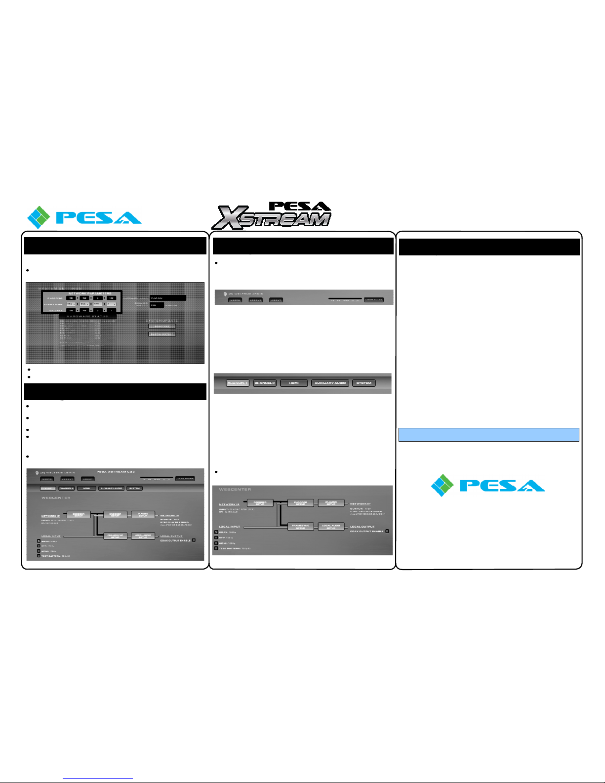
From the Systems page, enter the desired network communication parameters in the
cells as shown here.
Click Save to apply the new network parameter settings.
C22 will restart with new settings.
6
Step
M
ODIFY
C22 N
ETWORK COMMUNICATION
P
ARAMETERS(CONT
.)
7
Step
I
NTRODUCTION TO
C22 W
EBCENTER
C
ONTROL APPLICATION
Configuration and operational commands for C22 are entered through the webcenter
control application.
Webcenter is resident in the C22 processing engine and may be accessed through a
web browser such as Google Chrome or Mozilla Firefox.
Enter a username and password on the login page to open webcenter.
Login credentials for the default administrator account are:
Username – admin
Password – a
Following login, the control application always opens to the Webcenter page for
processing channel 1, as shown here.
7
Step
I
NTRODUCTION TO
C22 W
EBCENTER
C
ONTROL APPLICATION(CONT
.)
A brief description of control and configuration functions available from the webcenter
page is provided here. Detailed configuration and operation procedures are available
in the C22 User Guide.
- Channel 1 – Opens Webcenter set-up page for processing channel 1.
- Channel 2 – Opens Webcenter set-up page for processing channel 2.
- HDMI – Selects signal source for local HDMI output.
- Auxiliary Audio – Contains controls to configure analog audio inputs and software
faders to set level of auxiliary audio source. Also contains controls to select source
for local analog audio output as the audio signals from any of the encoder mixers
or local video output channels, and software faders to set level of local analog
audio outputs.
- System – Available only to administrative level users; opens control page for C22
system set-up parameters.
Part No. 81-9059-0732-0 Rev. A
Quick-Start Guide
C22
For further information, refer to PESA Xstream C22 User Guide
Step
S
YSTEM SET-UP AND CONFIGURATION
C
ONTINUED FROM PREVIOUS PAGE
7
Step
I
NTRODUCTION TO
C22 W
EBCENTER
C
ONTROL APPLICATION(CONT
.)
Set-up and configuration commands and settings for each processing channel are
entered through its webcenter page. An example page is shown below.
- Network IP (Input)– Displays IP address and status of the H.264 source connected
to the decoder, when IP streaming decoder is active.
- Local Input – Radio buttons allow selection of input port for local video source of
selected processing channel.
- Decoder Setup – Opens Decoder control page.
- Encoder Setup – Opens control pages for selecting output stream parameters and
streaming encoder configuration.
- IP Audio Setup – Opens control page for a two channel audio mixer. Use “faders”
and channel panning options to create a custom stereo audio track for AAC encoder
output.
- Frame Sync Setup – Allows selection of signal source and frame sync parameters
for local video output for selected processing channel.
- Local Audio Setup -Opens control page for a two channel audio mixer. Use
“faders” and channel panning options to create a custom stereo audio track for
embedding into local SDI video output.
- Network IP (Output) – Displays protocol of the output signal when the streaming
encoder is active. RTSP Player String displays a character string that contains
connection parameters for RTSP channel. Entering displayed connection
parameters to an RTSP client will initiate a connection with C22 server and establish
a streaming transport.
- Local Output – Displays output ports that are currently available as local signal
outputs, and the video format of output signal. A radio button allows you to select
whether rear panel BNC connector for processing channel is configured as an input
port or an output port.
P
AGE HEADER CONTROLS
& D
ISPLAYS
- Users – Allows an administrative level user to add users to the C22 system and
grant or revoke administrative access privileges.
- Logout – Logs user out of a C22 webcenter session.
- About – Provides system software/firmware revision data and other C22
information.
- Web server communication activity indicators – Provide visual display of
web server activity.
- User Guide – Opens a copy of the C22 User Guide.
M
ENU SELECT TABS
W
EBCENTER PAGE CONTROLS
& D
ISPLAYS
W
EBCENTER PAGE CONTROLS
& D
ISPLAYS(CONT
.)
*If any components are missing or damaged, contact PESA Customer Service by phone
or e-mail.
Customer Service: (256) 726-9222
Toll Free: (800) 323-7372
Fax: (256) 726-9268
Email: [email protected]
 Loading...