

Page 1

RCP-GPIO Control Panel
PESA Switching Systems
330A Wynn Drive
Huntsville, AL 35805
Document No. 81-9059-0386-0 Rev. B
Page 2

Manual Updates:
10/31/96 Manual released for initial printing.
03-05-01 Rev B: Deleted Printing Specification per ECO CE00113. GLT
Page 3

Ordering Assistance,
Service & Inquiries
Service and
Ordering
Assistance
Sales Office
PESA Switching Systems, Inc.
330A Wynn Drive
Huntsville, AL 35805
Main Numbers:
Tel: (205) 726-9200
Fax: (205) 726-9271
Service Department Numbers:
Tel: (205) 726-9222
Fax: (205) 726-9268
National Sales Office
PESA Switching Systems, Inc.
35 Pinelawn Road, Suite 99E
Melville, NY 11747
Tel: (800) 328-1008
Fax: (516) 845-5023
Page 4

NOTE
PESA reserves the right to change any information con-
tained in this manual without notice. Unauthorized copying,
modifications, distribution, or display is prohibited. All rights
reserved.
Please address all comments or suggestions concerning
this or other PESA manuals to:
Publications Department
Attn: Charles E. Jaynes
(Engineering Technical Writer)
PESA Switching Systems, Inc.
330A Wynn Drive
Huntsville, Alabama 35805
(205) 726-9200 EXT. 145
Page 5

ATTENTION
ALL EQUIPMENT
ITEMS MANUFACTURED BY OR SOLD
BY PESA SWITCHING SYSTEMS, INC.
ATTENTION
SHOULD BE SERVICED BY QUALIFIED SERVICE PERSONNEL OR BY
QUALIFIED SERVICE TECHNICANS
ONLY.
Page 6

Table of Contents
RCP-GPIO Control Panel
Section 1. Introduction
1.1 Manual Overview .......................................................................... 1.1
1.2 General Description ...................................................................... 1.2
1.3 Specifications ............................................................................... 1.3
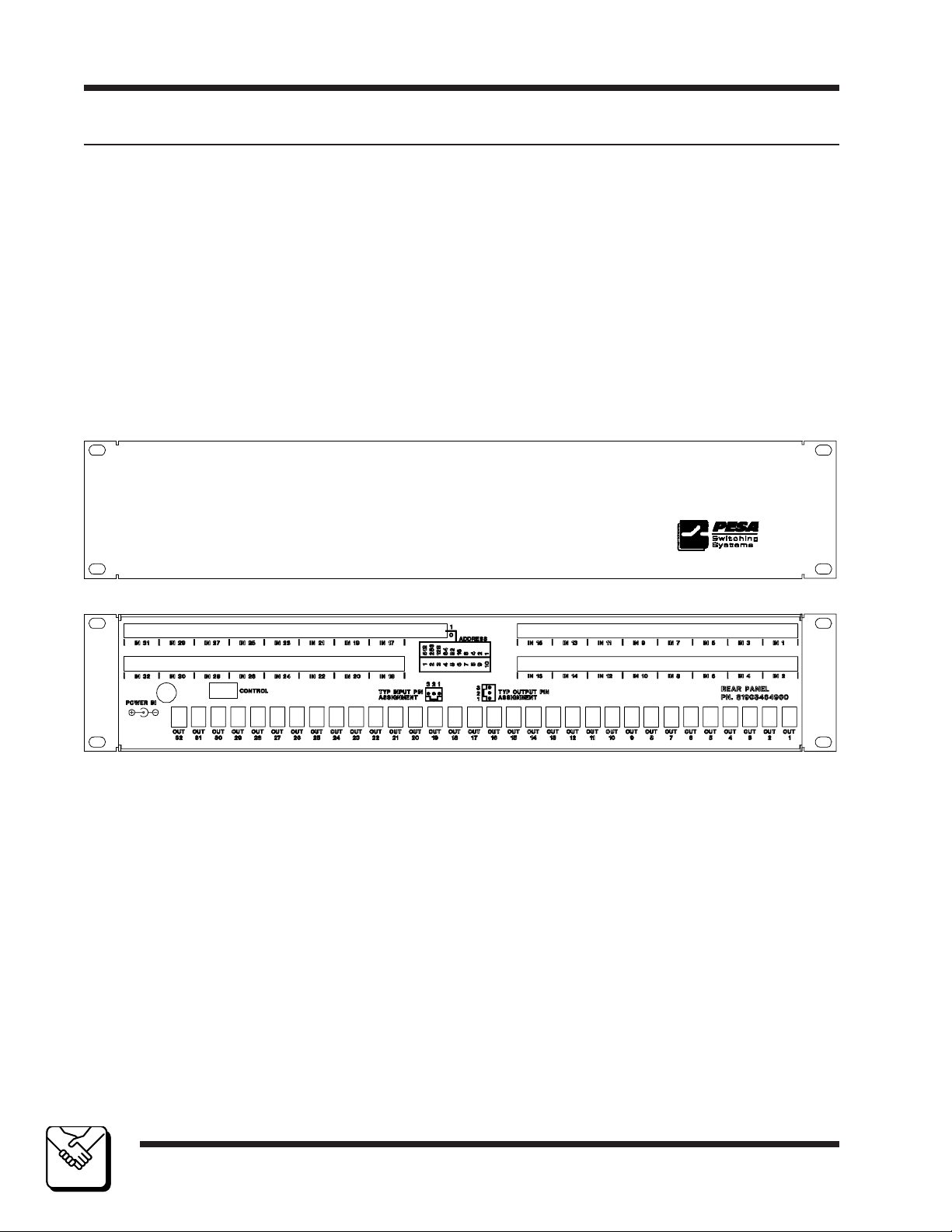
Figure 1-1 RCP-GPIO Control Panel (Front and Rear Views)............. 1.2
Section 2. Installation
2.1 Introduction ................................................................................... 2.1
2.2 Receipt Inspection ........................................................................ 2.1
2.3 Location and Mounting ................................................................. 2.1
2.4 Polling Address............................................................................. 2.3
2.5 Control Panel/Controller Interconnection...................................... 2.4
2.6 Wiring the Control Connector ....................................................... 2.5
2.7 Terminating Control Cable Runs .................................................. 2.6
2.8 Input Connection .......................................................................... 2.7
2.9 Output Connection ....................................................................... 2.9
2.10 Power Connections .................................................................... 2.9
Figures
Figure 2-1 RCP-GPIO Chassis Installation......................................... 2.2
Figure 2-2 DIP Switch Setting ............................................................. 2.3
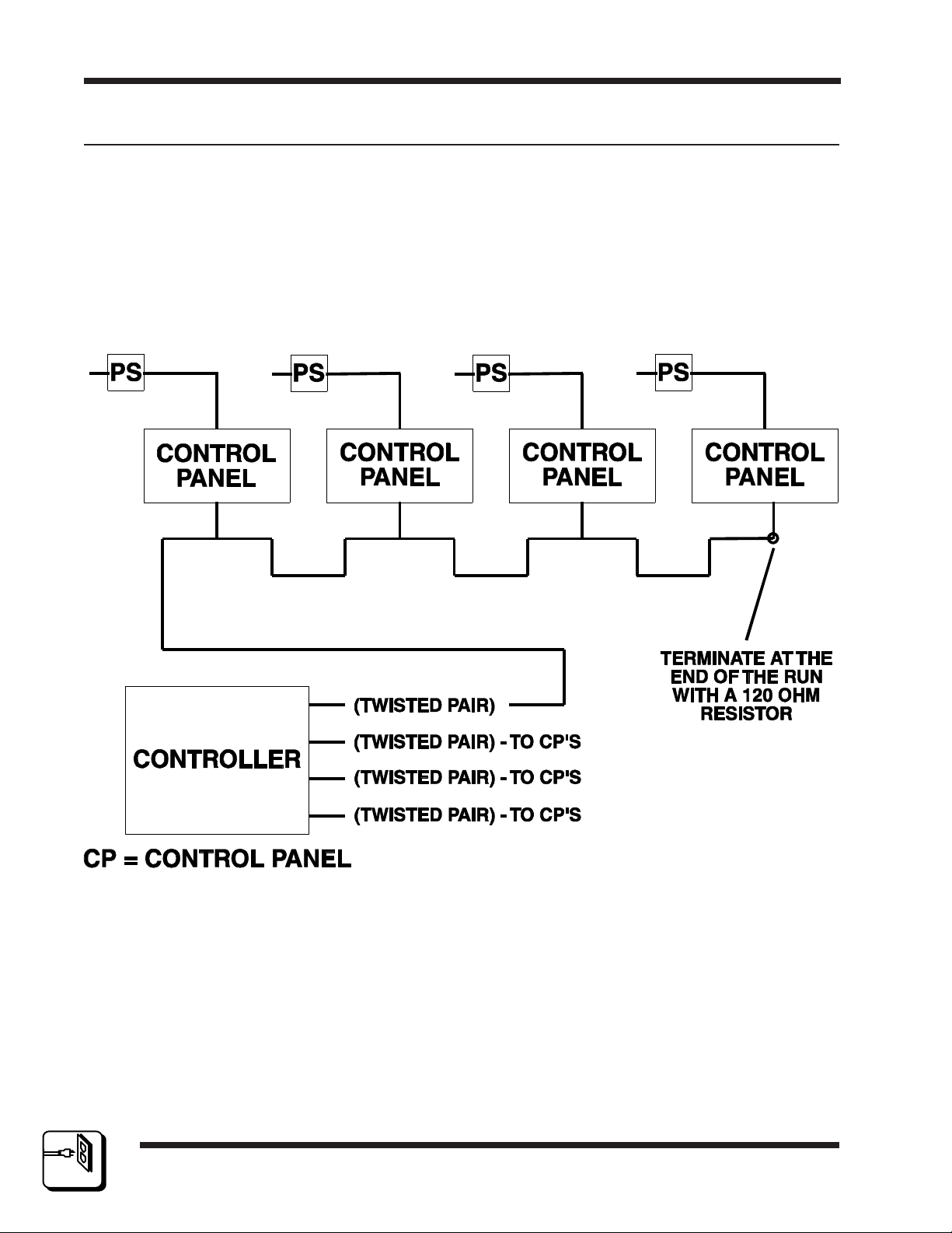
Figure 2-3 Typical Control Panel Controller Interconnection ............... 2.4
Figure 2-4 Wiring the Control Connector ............................................. 2.5
Figure 2-5 Terminating Control Cable Runs ........................................ 2.6
Figure 2-6 Typical Input (View One) .................................................... 2.7
Figure 2-7 Typical Input (View Two) .................................................... 2.8
Figure 2-7 Typical Output .................................................................... 2.9
Figure 2-8 Typical Control Panel Power Supply .................................. 2.10
10/96
P/N 81905903860
Figures
i
Page 7

Table of Contents
RCP-GPIO Control Panel
Section 3. Operation
3.1 Introduction ................................................................................... 3.1
General ..................................................................................... 3.1
3.2 General Purpose Inputs ................................................................ 3.1
3.3 General Purpose Outputs ............................................................. 3.2
3.4 Panel Configuration ...................................................................... 3.2
Configuring All Actions to be Taken on a Single Destination .... 3.4
Configuring Actions to be Taken on Different Destinations ...... 3.5
Section 4. Functional
4.1 Introduction ................................................................................... 4.1
4.2 GPIO Interface Card ..................................................................... 4.1
Power Supply............................................................................ 4.1
Microprocessor ......................................................................... 4.1
Clock ......................................................................................... 4.2
Reset ........................................................................................ 4.2
RS485 Communications ........................................................... 4.2
LED Driver Support................................................................... 4.3
Inputs Scan ............................................................................... 4.3
Output Relay Activation ............................................................ 4.4
Section 5. Maintenance
5.1 General ......................................................................................... 5.1
5.2 Preventive Maintenance ............................................................... 5.1
5.3 Test Equipment ............................................................................ 5.1
5.4 Corrective Maintenance ................................................................ 5.1
Factory Repair Service ............................................................ 5.2
Troubleshooting ........................................................................ 5.2
Figures
Table 5-1 Test Equipment Table ......................................................... 5.1
10/96
ii
P/N 81905903860
Page 8

Table of Contents
RCP-GPIO Control Panel
Section 6. Schematics
6.1 Schematics .................................................................................... 6.1
General ..................................................................................... 6.1
RCP-GPIO Control Panel Front View .................................................. 6.2
RCP-GPIO Control Panel Rear View .................................................. 6.3
RCP-GPIO Control Panel Assembly .................. CD63-0784 ............ 6.4
RCP-GPIO Interface Card ...................................CA25-1376 ............ 6.5
............................................................ SC33-1376 ............ 6.6
Section 7. Parts List
7.1 Parts List ....................................................................................... 7.1
General ..................................................................................... 7.1
RCP-GPIO Control Panel Assembly ................... 81906519250......... 7.2
RCP-GPIO Interface Card ...................................81906519260......... 7.3
RCP-GPIO Software............................................ 81906519330......... 7.4
10/96
P/N 81905903860
iii
Page 9
RCP-GPIO
Introduction Section 1
1.2 General Description
The RCP-GPIO Control Panel is a specialized control panel that can take electrical switch closure inputs and generate electrical switch closure outputs for use in
interfacing with external electronic equipment.
The RCP-GPIO Control Panel can be configured to operate in a variety of selection modes. The RCP-GPIO Control Panel offers 32 inputs and outputs that can
be configured to generate switches on the PESA router as well as generate tally.
The RCP-GPIO Control Panel comes packaged in a standard 19" two rack unit
chassis requiring 3" of depth. Power is supplied to the control panel through a
plug-in-the-wall type power pack.
1
1
INTRODUCTIO N
INTRODUCTIO N
page 1.2
Figure 1-1 RCP-GPIO Control Panel (Front and Rear Views)
10/96
P/N 81905903860
Page 10
RCP-GPIO
2.1 Introduction
This section details the RCP-GPIO Control Panel installation procedures.
The following topics are discussed:
Receipt Inspection
Location and Mounting
Polling Address
Control Panel and Controller Interconnection
Wiring the Control Panel Connector
Terminating Cable Runs
Power Connections
2.2 Receipt Inspection
The RCP-GPIO Control Panel is inspected and tested prior to shipment
from the PESA factory. Upon receipt, please inspect the unit for shipping
damage. If damage is detected, notify the carrier immediately and hold all
packing material for inspection. If assistance is required, please contact
PESA Customer Service at the telephone number listed in the front of this
manual.
Installation
Section 2
After unpacking, compare all parts received against the packing list. If the
unit is undamaged and all components have been received, proceed with
installation.
2.3 Location and Mounting
The RCP-GPIO Control Panel has been designed to fit in a standard
E.I.A. 19" equipment rack and use two rack units of space (3.5"). An area
should be selected where the ambient temperature will not exceed 40°C
inside the equipment rack, and where air can circulate freely. The control
panel should be mounted in an area convenient to control and power
connections. Sufficient space must be provided behind the equipment
rack to allow for the control and power cables. When the RCP-GPIO
Control Panel is supplied as part of a system including interconnecting
cables, rack layout drawings are usually provided. While adherence to the
rack layout drawings is not required, it will ensure that the interconnection
cables are the proper lengths. All mounting holes should be utilized and
the hardware be securely tightened.
10/96
P/N 81905903860
page 2.1
2
IN STA LLA TI O N
Page 11
RCP-GPIO
2.3 Location and Mounting Continued:
All interconnection cables should be strain relieved and secured to the
equipment racks or other supporting structures. Failure to provide adequate cable support may result in cables separating from connectors. If
cables are to be run under elevated flooring, they should be laid out in
cable racks if possible and tied to the cable racks as a guide. If cables are
run along the floor, do not allow then to lay in the work area behind the
racks. Stepping or tripping on the cables may result in connections being
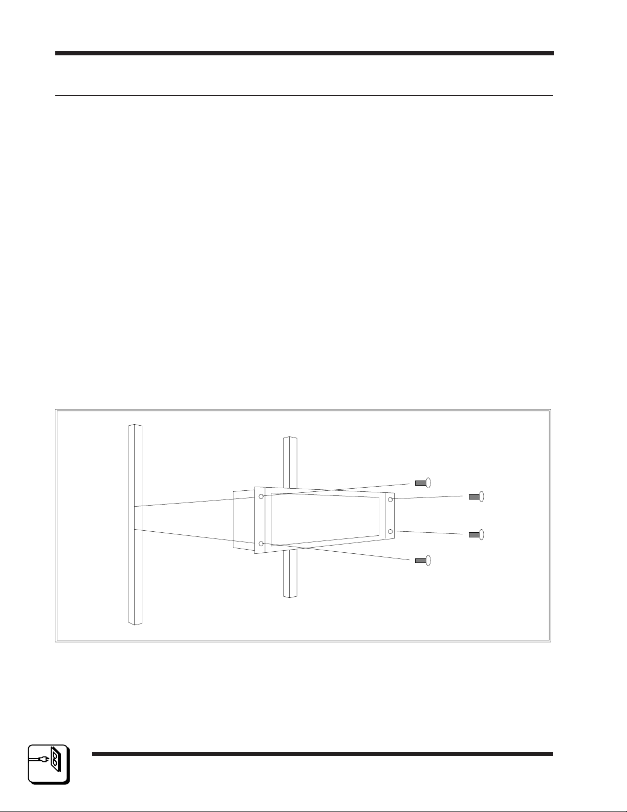
pulled free or wire breakage inside the insulation. Figure 2-1 illustrates
the chassis installation.
To install the RCP-GPIO Control Panel take the following steps:
1. Align the control panel chassis with a slotted opening in the rack.
2. Install the bottom screws first.
Section 2Installation
3. Install the top two screws.
4. Tighten all four screws securely.
2
IN STA LLA TI O N
page 2.2
Figure 2-1 RCP-GPIO Chassis Installation
10/96
P/N 81905903860
Page 12
RCP-GPIO
2.4 Polling Address
For the system controller to identify a particular control panel, a specific
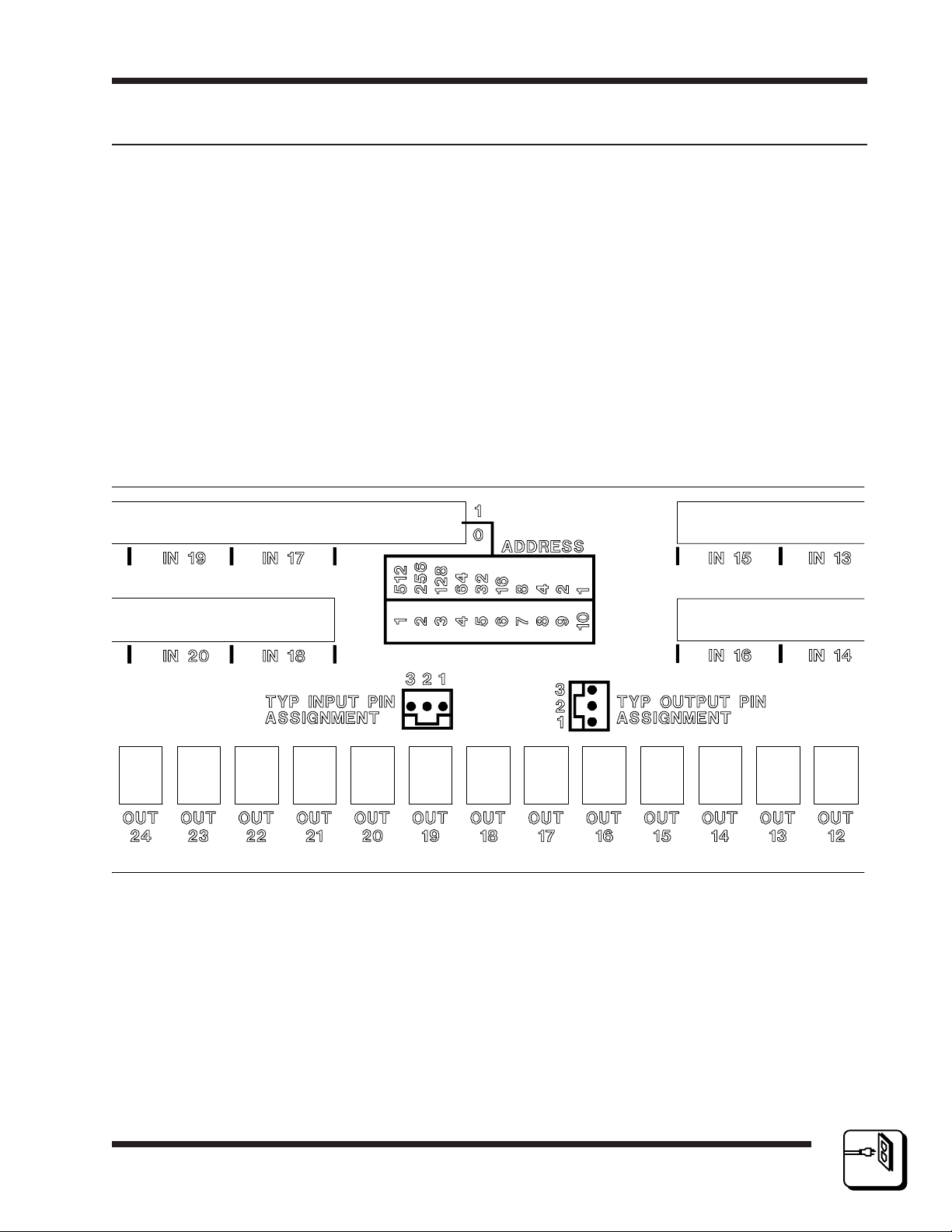
device number or polling address must be assigned to each panel. Sequential binary numbers (1 thorough 1023) are used for this purpose. The
appropriate binary number is entered into the control panel by setting an
internal 10-position DIP switch to the selected binary number. The DIP
switch is located on the Remote CPU Board and is accessible from the
rear of the unit. The panel address is normally assigned and entered at
the factory if the panel is purchased as part of a system and a design
guide has been completed by the user. If the panel is purchased separately, the user may be required to set the panel address.
EXAMPLE: To select polling address 21, set switches 10, 8, and 6 to the
"ON" or "1" position. See Figure 2-2.
Installation
Section 2
10/96
P/N 81905903860
Figure 2-2 DIP Switch Setting
page 2.3
2
IN STA LLA TI O N
Page 13
RCP-GPIO
2.5 Control Panel/Controller Interconnection
Each control panel has a single 3-pin MTA connector located on its rear
panel which is utilized for system communications to and from the controller. Control panels are daisy-chained to a communications port on the
rear panel of the system controller or to a communications port on the rear
panel of the routing switcher containing the system controller. Use
shielded twisted pair cable for all control panel communication port connections. See Figure 2-3.
Section 2Installation
2
IN STA LLA TI O N
page 2.4
Figure 2-3 Typical Control Panel Controller Interconnection
10/96
P/N 81905903860
Page 14
RCP-GPIO
Installation
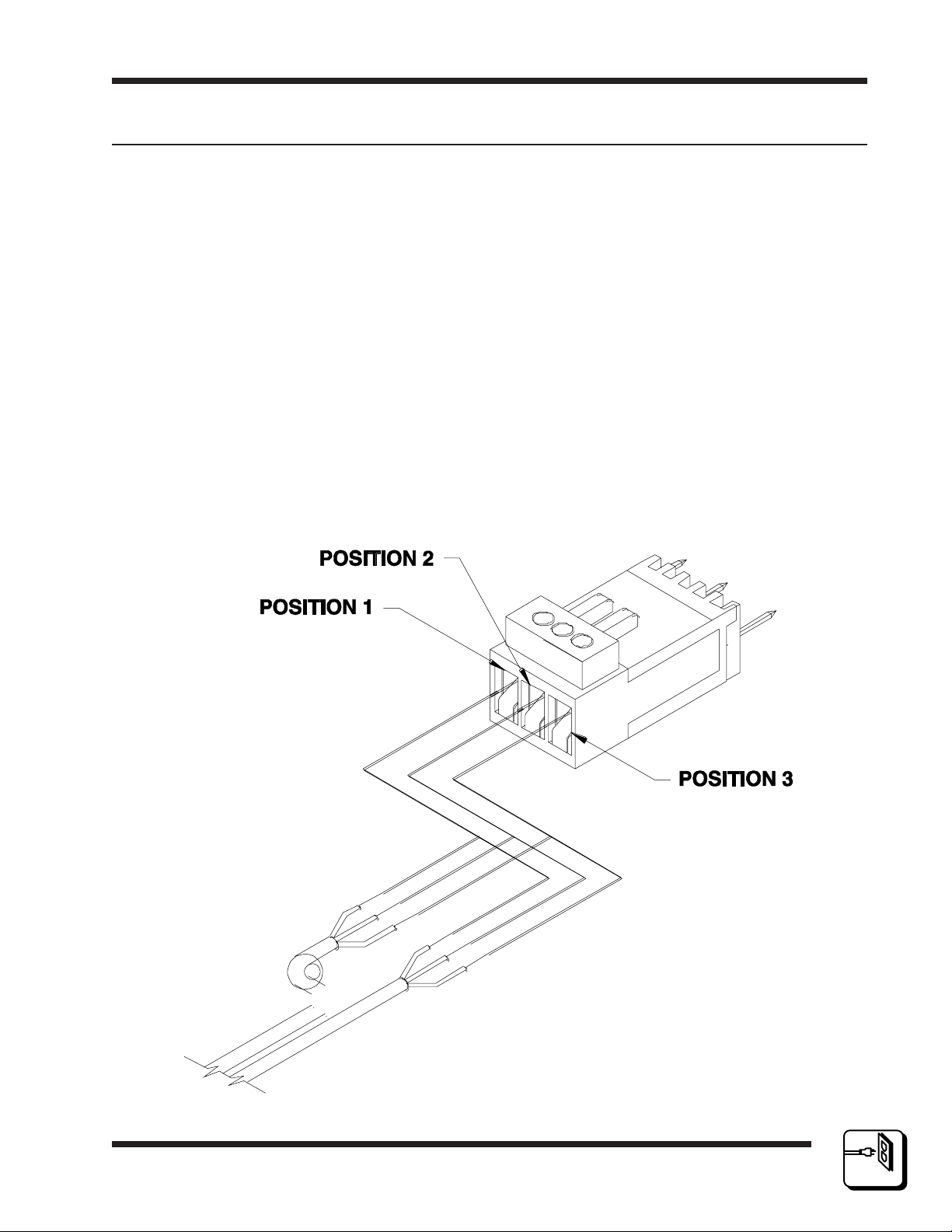
2.6 Wiring the Control Connector
Should an additional panel be added to your system, it will be necessary
to wire the connector using shielded twisted pair cable and a 3-pin MTA
connector using the following instructions. See Figure 2-4.
1. Remove approximately 1.5" of insulation from each of the two cables.
2. Remove approximately 0.5" of insulation from the black and red wires.
3. Twist together and insert the two black wire into position one. Crimp
down using a screwdriver.
4. Twist together and insert the two shield wires into position two. Crimp
down using a screwdriver.
5. Twist together and insert the two red wires into position three. Crimp
down using a screwdriver.
Section 2
10/96
P/N 81905903860
Figure 2-4 Wiring the Control Connector
page 2.5
2
IN STA LLA TI O N
Page 15
RCP-GPIO
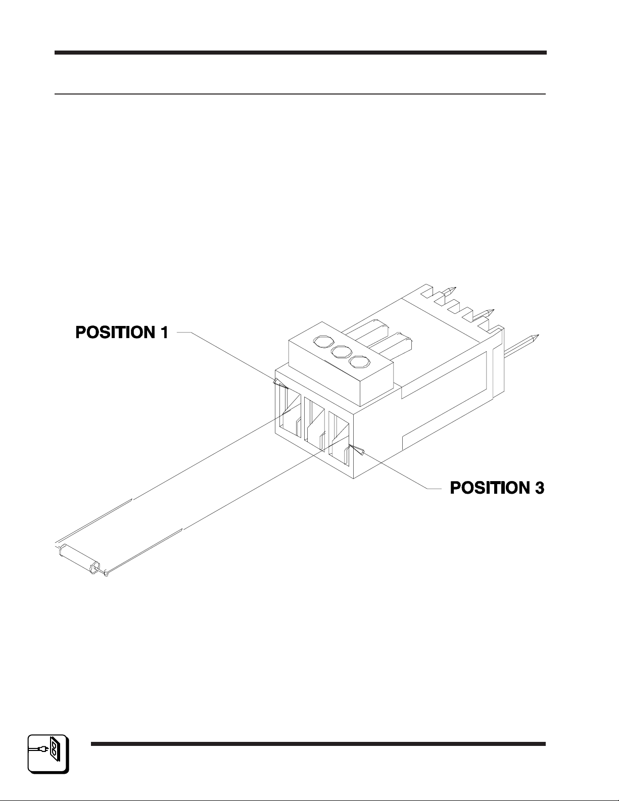
2.7 Terminating Control Cable Runs
Each cable run should be terminated with a 120 ohm, 1/4 watt 5% resistor. The cable is terminated internally at the controller. See Figure 2-5.
1. Un-crimp the black and red leads in positions one and three.
2. Insert the resistor leads into positions one and three along with the
black and red leads.
3. Crimp down using a screwdriver.
4. The shield wire remains in position two.
Section 2Installation
2
IN STA LLA TI O N
page 2.6
Figure 2-5 Terminating Control Cable Runs
10/96
P/N 81905903860
Page 16
RCP-GPIO
2.8 Input Connection
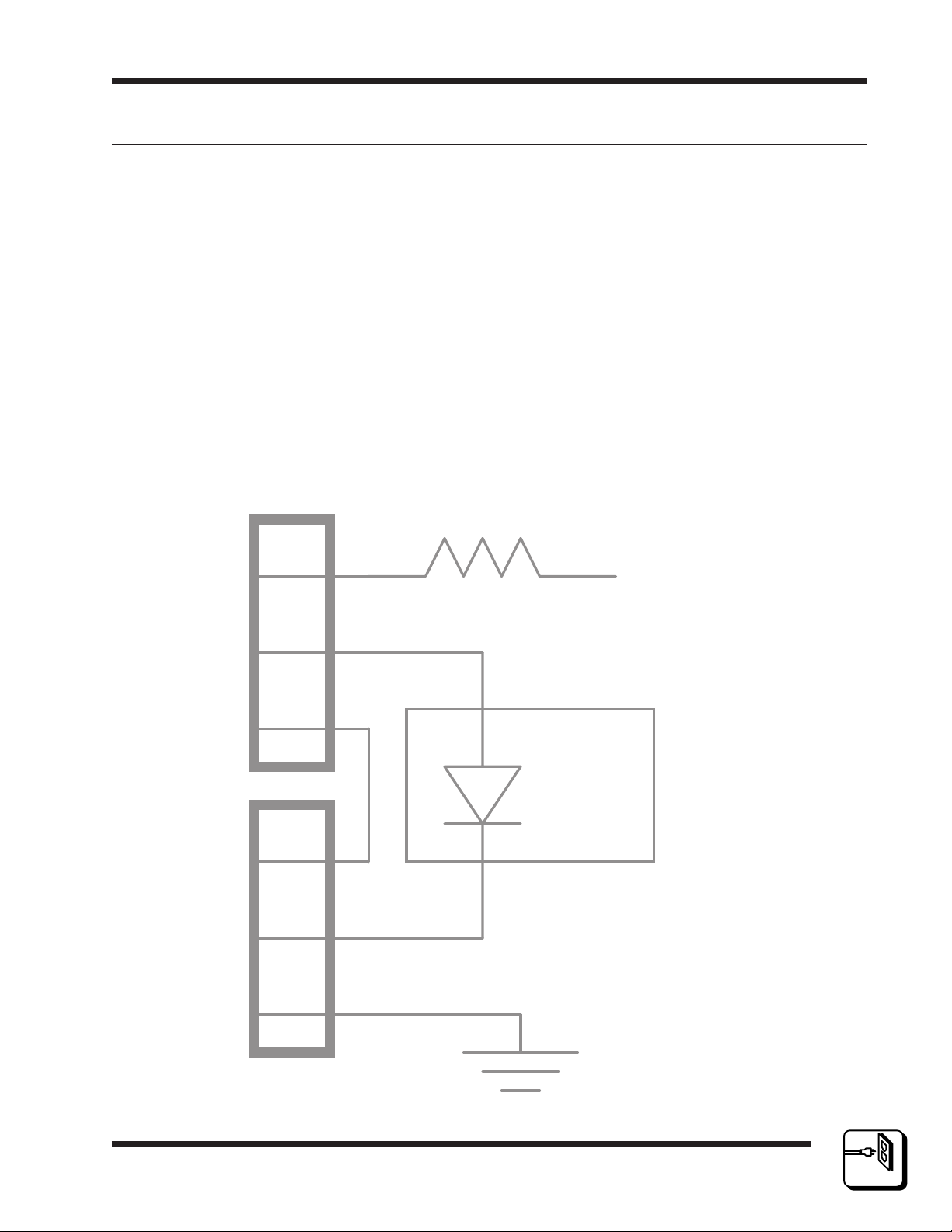
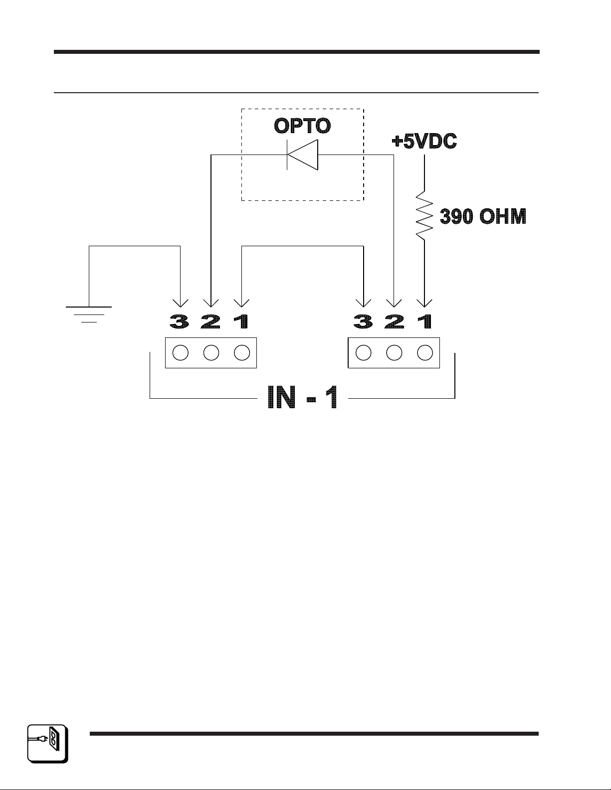
The RCP-GPIO Control Panel provides 32 opto-isolated inputs. Each
control panel input utilizes two 3-pin Weco input connectors (Figures 2-6
and 2-7). The two 3-pin input connectors allow the user to utilize internal
power and an internal 390 ohm pull-up resistor which can be connected to
the anode of the opto-isolator by connecting pins 1 and 2 of Input Connector One together. Input Connector Two provides the user with an open
collector connection on pin 2 to be utilized as a contact closure by user
supplied equipment. A GND connection is provided on pin 3 of Input
Connector Two for utilization by user supplied equipment. Alternatively,
an external current limit resistor can be installed between pins 2 and 3 on
Input Connector Two and user supplied power to pin 2 on Input Connector
One to activate the corresponding output. The input opto-diode is rated
for a maximum forward current of 60 milli-amps.
Installation
2KP
Section 2
9'&
2372
*1'
10/96
P/N 81905903860
Figure 2-6 Typical Input (View One)
page 2.7
2
IN STA LLA TI O N
Page 17
RCP-GPIO
2.8 Input Connection Continued:
Section 2Installation
Figure 2-7 Typical Input (View Two)
2
IN STA LLA TI O N
page 2.8
10/96
P/N 81905903860
Page 18
RCP-GPIO
2.9 Output Connection
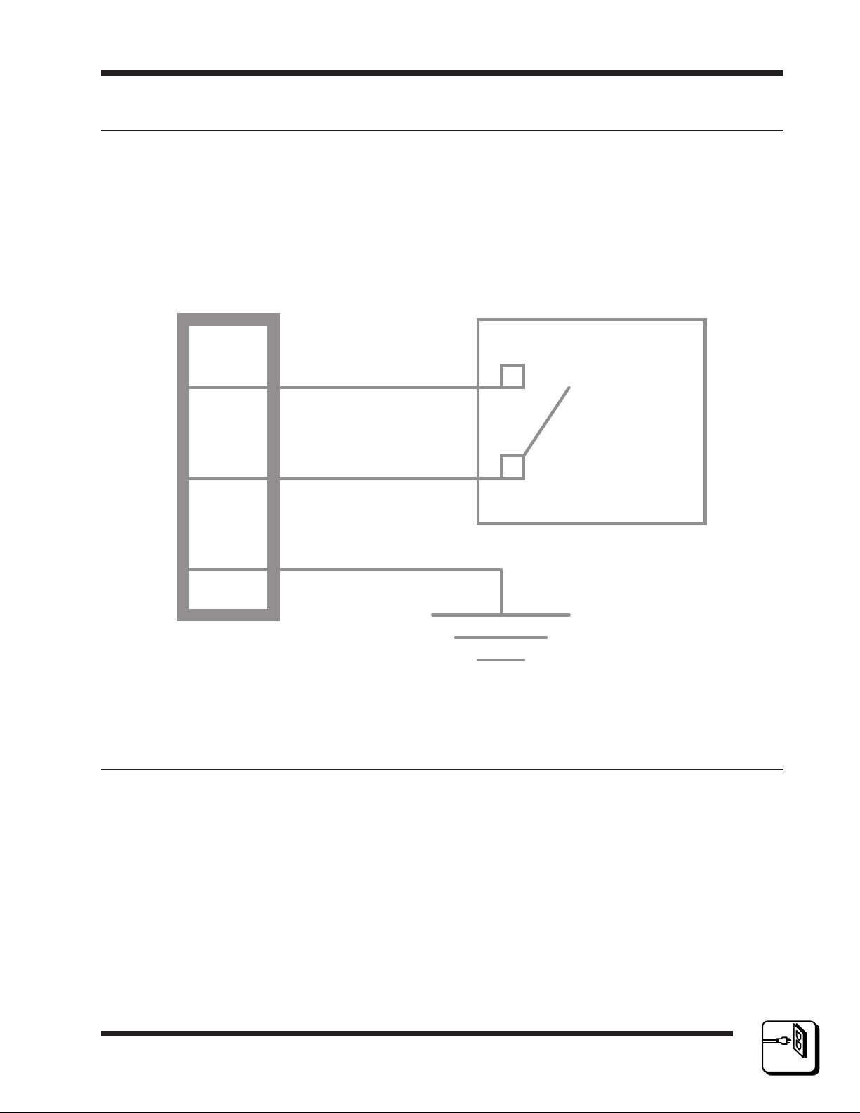
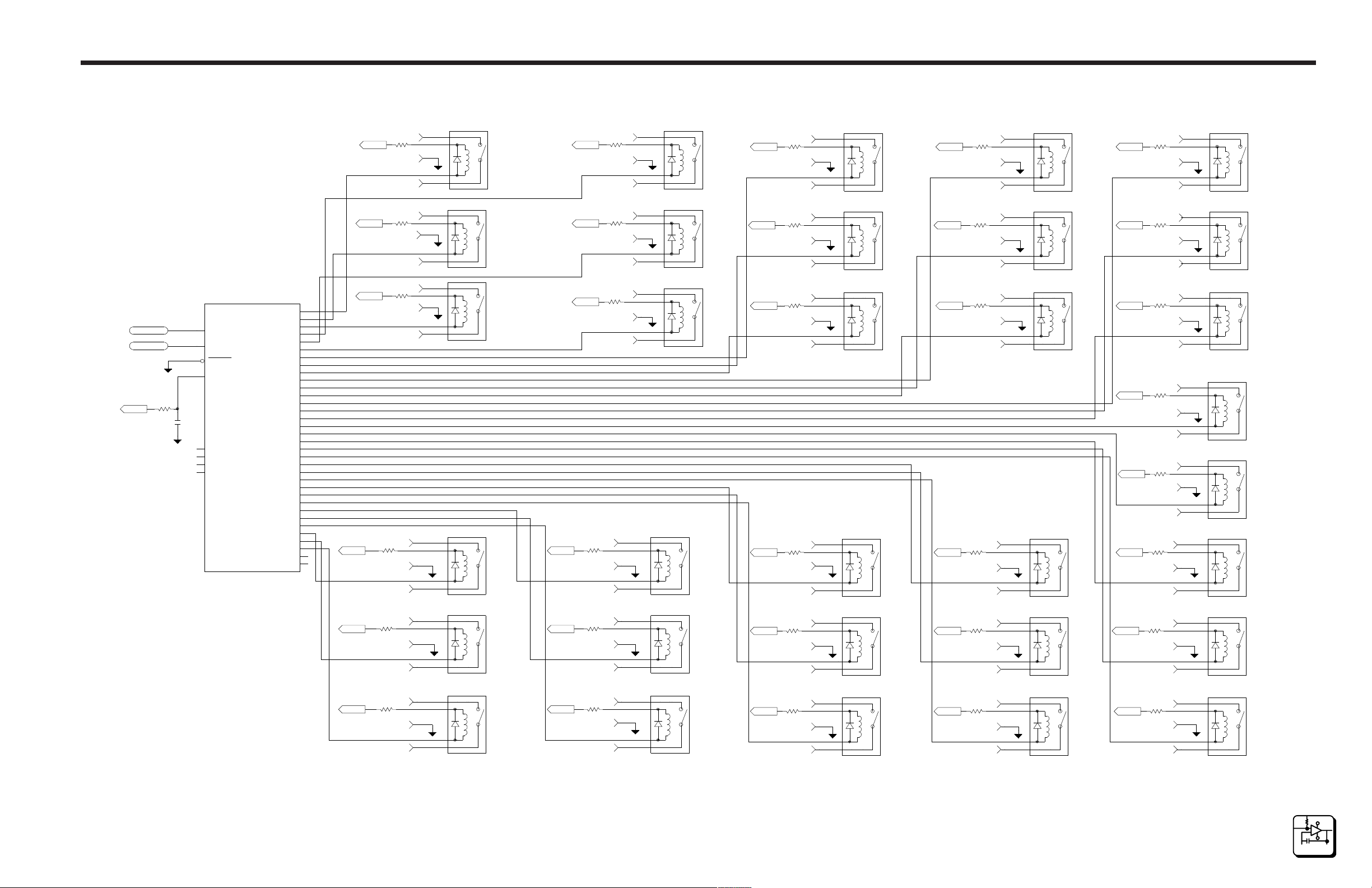
The RCP-GPIO Control Panel provides 32 form "A" relay outputs (Figure
2-8). Each control panel output utilizes one 3-pin Weco connector . Each
3-pin output connector provides; a signal ground connection (pin 3), a
relay wiper connection (pin 2), and a relay normally open connection (pin
1). The maximum voltage rating of the output relay contacts is 100VDC or
100V Peak to Peak AC. The maximum current rating of the output relay
contacts is 1A continuous or 0.5A switched.
Installation
Section 2
2.10 Power Connections
*1'
Figure 2-8 Typical Output
12
:
5HOD\
10/96
P/N 81905903860
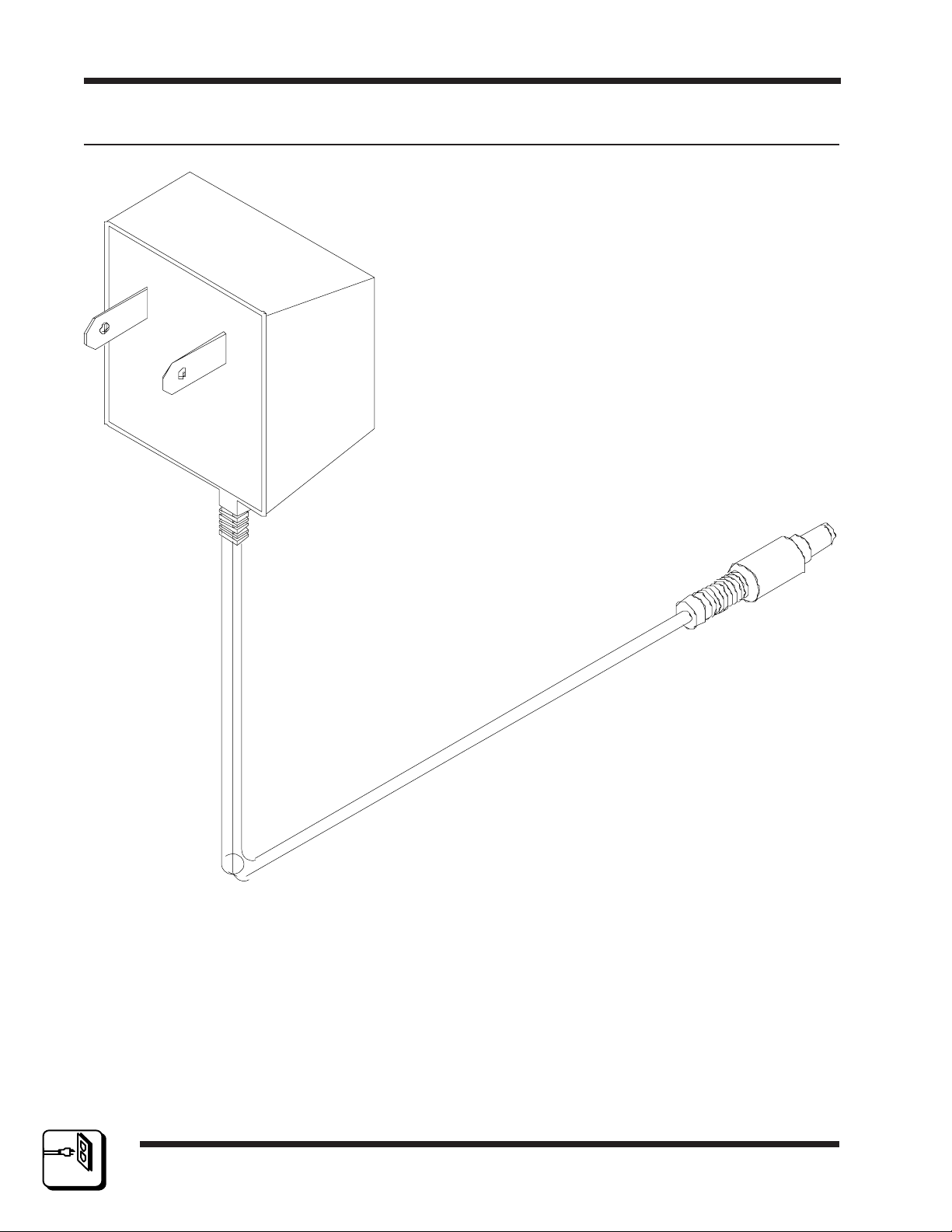
Power for the RCP-GPIO Control Panel is supplied by an external 7.5
VDC, 800 mA power supply.
Remove the power supply from the box it was shipped in and check to
insure that no damage has occurred in shipping. Verify that the power
supply is rated for the proper AC voltage (i.e. 115 VAC or 230 VAC) before connection to the AC line voltage. The power connector can now be
plugged into the POWER IN connector on the rear of the control panel.
The power supply will immediately power the unit upon connection to the
AC line voltage. See Figure 2-9.
page 2.9
2
IN STA LLA TI O N
Page 19
RCP-GPIO
2.10 Power Connections Continued:
Section 2Installation
2
IN STA LLA TI O N
page 2.10
Figure 2-9 Typical Control Panel Power Supply
10/96
P/N 81905903860
Page 20
RCP-GPIO
3.1 Introduction
The RCP-GPIO Control Panel is designed to be controlled by the 3300
Controller. Operations of the RCP-GPIO Control Panel require that it be
configured at the system controller utilizing the Win3300 Control System.
The RCP-GPIO is configured as an RCP-MLDT panel using the first 32 of
the data keys to define its behavior.
General
All RCP-GPIO Control Panels in a system are custom configured at the
factory prior to shipment. The information needed to configure the control
panels comes from the System Design Guide filled out by the customer.
However, if the system configuration changes, the RCP-GPIO Control
Panels can be re-configured on site using the control system configuration
software.
Operations Section 3
3.2 General Purpose Inputs
The RCP-GPIO panel is equipped with 32 general purpose inputs. The
input circuit to the GPIO panel consist of an opto-isolated input. The
circuit requires that the LED input be driven with sufficient current to
trigger the opto-coupled transistor and be read by the panel. The input is
optically isolated from the input LED to electrically isolate the panel's
circuits from the input interface. The input connectors provide a current
source and ground so that an isolated switch closure (such as a relay) can
be used to activate the inputs as well.
The RCP-GPIO inputs are treated by the panel the same as a user activating a data key on an RCP-MLDT panel. When an input is activated on
the GPIO panel, the 3300 reads the event as if it were a key press. As a
key press, the panel can act to take a switch or change the destination
being controlled by the panel. Given the manner in which the keys are
configured, the activation of the input may do a number of actions.
The most common instance of operation is assigning a source to a data
key on the panel. When the input associated with the data key is activated, the panel switches the source to the destination that the panel is
currently controlling.
10/96
P/N 81905903860 page 3.1
3
OPERATION
Page 21

RCP-GPIO
3.3 General Purpose Outputs
The RCP-GPIO panel is equipped with 32 general purpose outputs. The
output circuit of the GPIO panel consists of a relay output closure. When
activated, the panel activates the relay coil causing the relay switch to
close.
The GPIO panel outputs appear as MLDT panel LEDs to the 3300 control
system. When the panel lights an LED, the GPIO panel activates the
associated output. These LEDs are lit when the source assigned to the
key is switched to the panels current destination. In this manner, tally
can be generated when a source is connected to a certain destination.
3.4 Panel Configuration
The RCP-GPIO panel is configured in the system as a RCP-MLDT panel.
The manner in which the panel is configured determines how the panel
inputs and outputs will function.
Section 3Operations
Address: Decimal number from 1 to 1023 which is used to distinguish
each panel on the panel communications bus. Address must match the
DIP switch settings on the rear of the panel.
Panel Name: Any eight alphanumeric characters. Currently used only by
the controller configuration program to provide a user friendly method of
referring to each panel.
Requester Code: A number from 1 to 65535, this value is used by panels that need to share locks and protects. This is usually set to the same
value as the panel address.
Priority: Priorities are used when a panel attempts to set or clear a
destination protect or lock. Since the RCP-GPIO does not lock or unlock
its destination, this field does not have any real application. A master
priority of 0 is sufficient for this panel.
Status Method: The utilization of the default status is required by the
RCP-GPIO Control Panel.
Default Status Level: Level to be statused by the GPIO panel. This
level is important since it is used in the determination of which general
purpose output is activated for tally.
3
OPERATION
10/96
P/N 81905903860page 3.2
Page 22

RCP-GPIO
Operations Section 3
3.4 Panel Configuration Continued:
Default Destination Group: Destination group to be controlled by the
panel when first powered up.
Level List: List of levels to controlled by the panel. Any level not assigned in the Level List will not be accessible to or affected by panel
operations.
Include Source List: List of all source groups accessible by the panel.
Not applicable to the RCP-GPIO panel.
Include Destination List: List of all destination groups controllable by the
panel. Not applicable to the RCP-GPIO panel.
Salvo List: List of all salvoes the panel can execute. Not applicable to
the RCP-GPIO panel.
Data Key Assignment List: List containing the assignment of all data
keys as configured by you. Though the RCP-MLDT allows 72 data keys,
the RCP-GPIO is only functional for the first 32 of those keys.
The RCP-GPIO panel uses only two of the data key types: Source and
Destination. Though the RCP-MLDT supports many other types of key
options, the other types should be avoided unless you have a very good
understanding of the RCP-MLDT and RCP-GPIO panels.
Salvo Key Assignment List: Since salvos are not accessible from the
RCP-GPIO panel, this list is not applicable and may be left blank.
Soft Keys: Since soft keys are not accessible from the RCP-GPIO panel,
this item is not applicable and may be left blank.
The following is an example of configuring the RCP-GPIO for two different
types of applications.
10/96
P/N 81905903860 page 3.3
3
OPERATION
Page 23

RCP-GPIO
3.4 Panel Configuration Continued:
Configuring All Actions to be Taken on a Single Destination
If all actions initiated by the panel are to be taken on a single destination,
then the following is required for configuring the panel.
1. Enter a panel name. This is an optional name for your benefit that
allows you to identify the function of the panel.
2. Enter the address for which the panel is coded. This address matches
the binary encoded value on the DIP switch on the back of the panel.
3. Enter a requester code. Usually this is the same as the panel address.
Requester codes are used when locks and protects need to be shared
among a number of panels.
4. Enter the lock priority. Since this panel performs no lock actions, a
value of 0 (super user) is adequate.
Section 3Operations
5. Enter the status level. This is the level of control that is of most interest to the panel. It is the level of control that will determine the tally
that activates the GPIO panel outputs.
6. Enter the status method. The selection should be the default (DEF).
7. Enter the default destination. The selected destination is the destination on which all panel actions are taken.
8. Levels of control list determines which levels of control the panel will
take switches on. Selection of the ALL list will insure that actions are
taken on all levels of control.
9. Source, destination, and salvo include lists do not have any impact on
the operation of the panel. Selection of the ALL list is adequate for
these panels.
10.The data key list is the list that determines what switches will be taken
when a particular input is activated as well as what outputs are activated when a certain switch status occurs. Data key associations to
inputs/outputs are 1-to-1 so that data key #1 is associated with input
and output #1 on the GPIO panel, etc. In this configuration, data keys
are assigned desired sources (Source Key Type) that correspond to
each input/output that will be activated.
3
OPERATION
10/96
P/N 81905903860page 3.4
Page 24
RCP-GPIO
Operations Section 3
3.4 Panel Configuration Continued:
Configuring All Actions to be Taken on a Single Destination Cont:
Given a configuration that has the source VTR 1 associated to data key
#3, when input #3 is activated on the panel, VTR 1 is taken to the destination controlled by the panel. The output associated with the source VTR1
becomes active.
If the same source is used more than once on a panel (i.e. assigned to
more than one data key) and is used for GPIO panel output activation, the
user will need to OR the switch closures together. The panel does not
guarantee which output will activate when the source is switched to the
panels destination.
The data key list only needs the first 32 data keys configured. Keys 3372 need not be configured.
11.Salvo key and soft keys are not used by this configuration. They do
not need to be configured on the panel.
Configuring Actions to be Taken on Different Destinations
The RCP-GPIO panel may be configured to initiate switches on different
destinations. Doing so has some limitations in that each input event must
go to two separate inputs. In addition, the use of the general purpose
outputs is limited as the panel only provides tally for one destination at any
one time.
1. Enter a panel name. This is an optional name for your benefit that
allows you to identify the function of the panel.
2. Enter the address for which the panel is coded. This address is coded
on the DIP switch on the back of the panel.
3. Enter a requester code. Usually this is the same as the panel address.
Requester codes are used when locks and protects need to be shared
among a number of panels.
4. Enter the lock priority. Since this panel performs no lock actions, a
value of 0 (super user) is adequate.
5. Enter the status level. This is the level of control that is of most inter-
est to the panel. It is the level of control that will determine the tally
that activates the GPIO panel outputs.
10/96
P/N 81905903860 page 3.5
3
OPERATION
Page 25

RCP-GPIO
3.4 Panel Configuration Continued:
Configuring Actions to be Taken on Different Destinations Cont:
6. Enter the status method. The selection should be the default (DEF).
7. Enter the default destination. The selected destination is the destination that the panel controls coming out of reset. This will be used for
status until an input is activated on the panel.
8. Levels of control list determines which levels of control the panel will
take switches on. Selection of the ALL list will insure that actions are
taken on all levels of control.
9. Source, destination, and salvo include lists do not have any impact on
the operation of the panel. Selection of the ALL list is adequate for
these panels.
Section 3Operations
10.The data key list is the list that determines what switches will be taken
to a which destinations when a particular input is activated. When
configuring for this scenario, two successive data keys must be assigned for each input. The first key (lower number) is assigned the
destination (Destination Key) that will be switched. The second key is
assigned the source (Source Key) that is to be switched to the destination. (Note that the destination key must be the lower number key as
the panel reacts to lower key inputs before higher key inputs. Failure
to do this will cause the switch to be taken before the proper destination is selected.)
Given a configuration that has source VTR 1 to be taken to MONITOR 1
on an input event, MONITOR 1 is the destination assigned to key #1 and
VTR 1 is the source assigned to key #2. The input circuits to inputs #1
and #2 are paralleled. When the input is activated, the panel switches
control to the destination MONITOR 1 and then switches the source VTR
1 to MONITOR 1.
The data key list only need the first 32 data keys configured for 16 switching events. Keys 33-72 need not be configured.
3
OPERATION
11.Salvo key and soft keys are not used by this configuration. They do
not need to be configured on the panel.
10/96
P/N 81905903860page 3.6
Page 26

RCP-GPIO
Functional Section 4
4.1 Introduction
The RCP-GPIO Control Panel contains one printed circuit board assembly; the GPIO Interface Card. The GPIO Interface Card contains a microprocessor that controls the panel's operation and communicates with the
routing switching system controller. The GPIO Interface Card also contains the interface connections used by the external relays to the control
the routing switcher system. The following manual section contain a detailed description of the GPIO Interface Card.
4.2 GPIO Interface Card
The GPIO Interface Card contains all of the circuitry necessary to communicate with the system controller and to interface with 32 inputs and 32
outputs. The circuitry on the GPIO Interface Card may be divided into the
following sections: Power Supply, Microprocessor, Clock, Reset, and
RS485 Communications. The GPIO Interface Card also contains circuitry
which scans the inputs and activates the corresponding output relays. The
following paragraphs explain each section in detail.
Power Supply
The power supply circuit on the GPIO Interface Card consists of a 7805
+5V regulator and filter capacitors. Unregulated DC voltage (7.5 to 9 VDC)
is supplied by an external power supply via J65. The voltage regulator
(U39) reduces the voltage to 5.0 VDC. C10 and C9 provide filtering for the
input and output of the regulator. Bypass capacitors (0.1 uF) are scattered
about the assembly to provide power supply bypassing for the individual
integrated circuits (ICs). Unregulated voltage (Vext) is also provided to the
output relay circuits.
Microprocessor
The heart of the GPIO Interface Card is the Motorola 68HC11 microprocessor (U35). This IC contains the microprocessor and peripheral circuitry
used to operate the control panel. In addition, the 68HC11 contains a
PROM loaded with the software used to operate the control panel. The
68HC11 is operated in the multiplexed mode. In this mode port B (U35 pin
35-42) provides the address byte (A0-A2). Port C (U35 pins 9-16) provides
the data byte (D0-D7).
10/96
P/N 81905903860
page 4.1
4
FU NCTIONAL
DES CRIPTION
Page 27
RCP-GPIO
4.2 GPIO Interface Card Continued:
Microprocessor Continued:
During the first half of the bus cycle, port C presents the lower address
byte (A0-A2). This information is presented to U38 and remains stable until the beginning of the next bus cycle when KBD_SEL is driven high by
the processor. During the last half of the bus cycle port C presents data
during write cycles and accepts data during read cycles.
Clock
The master system clock is provided by oscillator U6 pin 8. SYSCLK is
available to the processor (U35 pin 7). The frequency of SYSCLK is
7.3728 MHz. This value was chosen to provide an appropriate frequency
for the baud rate generator inside the 68HC11.
Reset
Section 4Functional
As with all microprocessors, the 68HC11 requires initialization during
power-up. The 68HC11 requires that the RESET pin (U35 pin 17) be held
low for 4064 cycles of E clock (2.2 mS @ 1.8432 MHz E clock). In addition
the RESET pin must be held low while VDD is below legal limits to protect
the internal EPROM register contents. A Maxim MAX690 chip (U34) performs the reset function for the 68HC11. The MAX690 monitors the supply
voltage and asserts RESET (U34 pin 7) whenever VCC falls below 4.5
VDC. The RESET signal is guaranteed to be asserted for a minimum of
50 mS after VCC rises above 4.75 VDC. This is more than adequate to
meet the 2.2 mS requirement of the 68HC11.
RS485 Communications
Communication between the panel and the system controller is accomplished by the 68HC11 internal serial communications interface (SCI). The
SCI is an asynchronous receiver/transmitter, sometimes referred to as a
UART. The RS485 standard is used for the electrical interface between
control panels and the system controller. A 75ALS176 (U37) chip is used
convert between RS485 and the levels required by the SCI. Transmit data
(TXD) is presented by the SCI on U35 pin 21. This signal drives the input
to the RS485 transceiver on U37 pin 4. Data received from the system
controller is converted to the appropriate levels by the RS485 transceiver
and is presented on U37 pin 1. This received data (RXD) signal is then fed
to the SCI receiver at U35 pin 20. Since the RS485 interface requires the
transmitter to be tri-stated when not is use, a third signal is required to enable/disable the RS485 transmitter.
4
FU NCTIONAL
DES CRIPTION
page 4.2
10/96
P/N 81905903860
Page 28

RCP-GPIO
Functional Section 4
4.2 GPIO Interface Card Continued:
RS485 Communications Continued:
The processor provides the TX_ENABLE signal under software control at
U35 pin 25. This signal is connected to the RS485 transceiver at U37 pin
3. When TX_ENABLE is asserted (high), U37 drives the RS485 bus (U37
pins 6 and 7 to J4 pins 1 and 3). When TX_ENABLE is negated (low),
U37 ceases driving the bus and allows other devices to drive the bus. During reset, the TX_ENABLE signal from the processor is initialized to an input and is not driven to a particular state. A pull-down resistor (R35) has
been added to ensure that U37 does not drive the RS485 bus during
power-up or other reset conditions. A shield connection is provided for the
RS485 bus on J66 pin 2.
LED Driver Support
The 68HC11 processor uses the internal synchronous peripheral interface
(SPI) under software control to drive the GPIO Interface Card's LED circuitry. LDATA is presented as serial bit stream on U36 pin 25. LCLK is
presented on U36 pin 24. U36 accepts LDATA on the rising edge of LCK.
The data stream generated is compatible with that required by National
MM5450 LED driver chips.
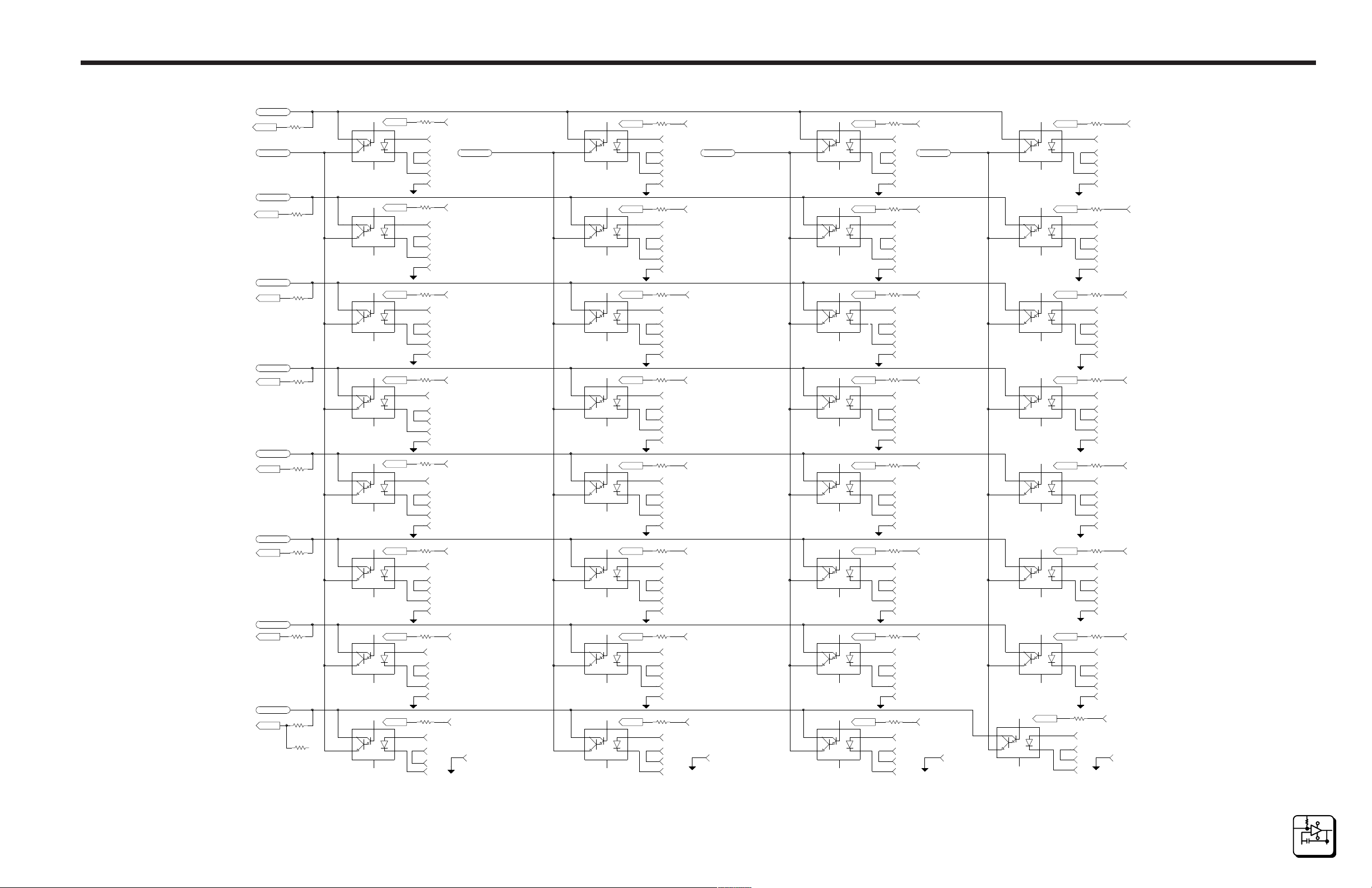
Inputs Scan
The GPIO Interface Card contains circuitry capable of scanning up to 64
inputs. The scan circuit is arranged as an eight row by eight column array.
While the scan circuitry is capable of serving 64 push-buttons, the GPIO
Interface Card has circuitry for 32 inputs. To scan the inputs, the microprocessor performs read cycles that enable KRD_SEL. This occurs for the
address range of 800h to FFFh. KRD_SEL provides an active low chip select for the bus transceiver (U1 pin 19). The three least significant address
bits (A0-A2) are connected to the input of the decoders (U38 pins 1, 2,
and 3). One of the eight active low outputs of the decoders is selected by
placing the appropriate address on the input of the decoders. Since partial
decoding is used, the keyboard circuitry is mapped to several addresses
within the KRD_SEL address range. The software in the microprocessor
only uses the lowest available addresses to access the keyboard.
10/96
P/N 81905903860
page 4.3
4
FU NCTIONAL
DES CRIPTION
Page 29

RCP-GPIO
4.2 GPIO Interface Card Continued:
Inputs Scan Continued:
Although the GPIO Interface Card only uses rows 0-3, the microprocessor
still scans all 16 rows. Each row of push-buttons contains up to eight individual switches. Example: KB_ROW0 will simultaneously enable inputs 1-
8. If any of these inputs are activated, the active low signal will be passed
through the input jumpers to one of the eight column signals (KB_COL0
through KB_COL7). If the input is not activated the column signal will be
pulled high by resistor pack RP1. The KRD_SEL signal also enables U1 to
place the KB_COL signals on the data bus. Thus, by performing a read
cycle at address 800h, the microprocessor can determine the state of inputs 1-8 by looking at the state of data bits D0-D7. If input 1 is activated,
then D0 will be low. Likewise, if input 2 is activated, D1 will be low. The
status of the entire input array may be determined by performing successive reads of each row of the array.
Section 4Functional
Output Relay Activation
While the GPIO Interface Card contains circuitry capable of activating up
to 34 output relays, the GPIO only uses 32 of the output relay driver circuits (one per output). The drive for the output relay circuits is provided by
U36 (MM5450V LED Driver). The microprocessor sends a serial data
stream to the MM5450V LED driver using the LDATA (pin 25 of LED
driver chip) and LCLK (pin 24 of the LED driver chip) signals. The enable
signal (pin 26 of the LED driver chip) is always asserted (active low). The
output current used drive each LED is enabled by the brightness pin of the
LED driver (pin 21). Resistor R323 sets the current flow through the output
relays. The LDATA line is latched into the LED driver chip on the rising
edge of LCLK.
4
FU NCTIONAL
DES CRIPTION
page 4.4
10/96
P/N 81905903860
Page 30
RCP-GPIO
Maintenance Section 5
5.1 General
The RCP-GPIO Control Panel is a solid state electro-mechanical device
designed to give long, trouble free service with minimum maintenance
requirements. If problems do occur, follow the troubleshooting procedure
provided. If additional technical assistance is required, refer to the general
assistance and service information in the front of this manual.
NOTICE
THIS EQUIPMENT CONTAINS STATIC SENSITIVE DEVICES. IT IS RECOMMENDED
THAT A GROUNDED WRIST STRAP AND MAT BE USED WHILE MAKING REPAIRS.
5.2 Preventive Maintenance
There is little need for performing preventive maintenance on the RCPGPIO Control Panel other than the normal care which should be given to
any high quality electronic equipment.
5.3 Test Equipment
The test equipment recommended for servicing the RCP-GPIO Control
Panel is listed in Table 5-1. Equivalent test equipment may be used.
Table 5-1 Test Equipment Table
EQUIPMENT FUNCTION
Oscilloscope - 20MHz or Higher Waveform Monitoring and Tracing
VOM - 20,000 Ohm per Volt or Higher Voltage and Resistance Measurements
5.4 Corrective Maintenance
The following paragraphs provide information to assist the servicing technician in the maintenance of the RCP-GPIO Control Panel. The functional
description (Section 4) contains assembly and circuit level information to
help identify specific problems.
10/96
P/N 81905903860 page 5.1
5
MAINT ENANCE
Page 31

RCP-GPIO
Section 5Maintenance
5.4 Corrective Maintenance Continued:
Factory Repair Service
If desired, equipment items or assemblies may be returned to the PESA
factory (transportation prepaid) for repair. Refer to the General Assistance
and Service Information Sheet found in the front of this manual. Call the
PESA Service Department (the phone number is listed on Service Information Sheet) for a RMA number prior to shipping an equipment item to
the PESA factory for repair.
NOTE
PACK THE EQUIPMENT SECURELY AND LABEL WITH THE CORRECT ADDRESS.
PROPER PACKAGING SAVES MONEY. THE SMALL AMOUNT OF EXTRA CARE AND
TIME IT TAKES TO CUSHION A PART OR UNIT PROPERLY MAY PREVENT COSTLY
DAMAGE WHILE IN TRANSIT. MAKE CERTAIN THAT THE ADDRESS IS BOTH LEGIBLE AND COMPLETE. FAILURE TO DO SO OFTEN RESULTS IN DELAY OR EVEN
LOSS.
Troubleshooting
Troubleshooting the RCP-GPIO Control Panel requires the routing
switcher system to be used as a test fixture. The RCP-GPIO Control
Panel will not function except as part of routing switcher system. The only
troubleshooting which can be accomplished without opening the control
panels is to check input power (from plug-in power supply).
To open a control panel for troubleshooting, remove the front cover and
disassemble the unit as far as required to gain access to the component
side of the circuit assemblies. Place the disassembled panel on a nonconductive surface and arrange the parts so the unit can be operated. You
must be able to check the operation of the inputs and outputs while observe the resulting status. You must also have sufficient access to the
circuit assemblies to measure voltage or observe waveforms.
Procedure: Put the RCP-GPIO Control Panel through the operating
sequence as described in operation section of this manual. Refer to Section 3.
If the control panel is unresponsive, there may be a power problem
or the microprocessor on the GPIO Interface Card is not operating.
5
MAINT ENANCE
10/96
P/N 81905903860page 5.2
Page 32

RCP-GPIO
Maintenance Section 5
5.4 Corrective Maintenance Continued:
Troubleshooting Continued:
1. Refer to the Power Distribution discussion in Section 4. Refer to the
Remote CPU Assembly Schematic in Section 6 if it is necessary to
make voltage checks at the chip or component level.
2. If the power is functioning properly, the microprocessor is not function-
ing. The microprocessor requires a clock, a power-up reset, and communications from the system controller. Refer to the GPIO Interface
Card functional description in Section 4.
10/96
P/N 81905903860 page 5.3
5
MAINT ENANCE
Page 33

RCP-GPIO
6.1 Schematics
General
This section contains the schematic diagrams and parts location diagrams
for the RCP-GPIO Control Panel. Please refer to this section when
troubleshooting the equipment or replacing defective parts.
Description Dwg No. Page No.
RCP-GPIO Control Panel Front View 6.2
RCP-GPIO Control Panel Rear View 6.3
RCP-GPIO Control Panel Assembly CD63-0784 6.4
RCP-GPIO Interface Card CA25-1376 6.5
Schematics Section 6
SC33-1376 6.6
10/96
P/N 81905903860
page 6.1
6
SCHEMATICS
Page 34
RCP-GPIO Control Panel
Schematics Section 6
10/96
P/N 81905903860
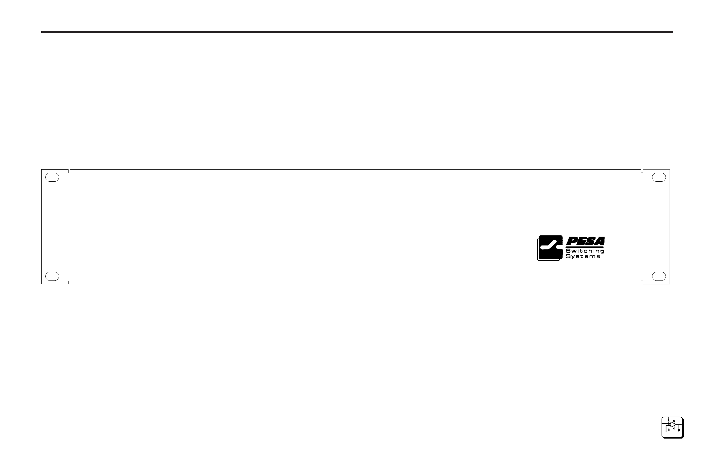
RCP-GPIO Control Panel Front View
page 6.2
6
SCHEMATICS
Page 35
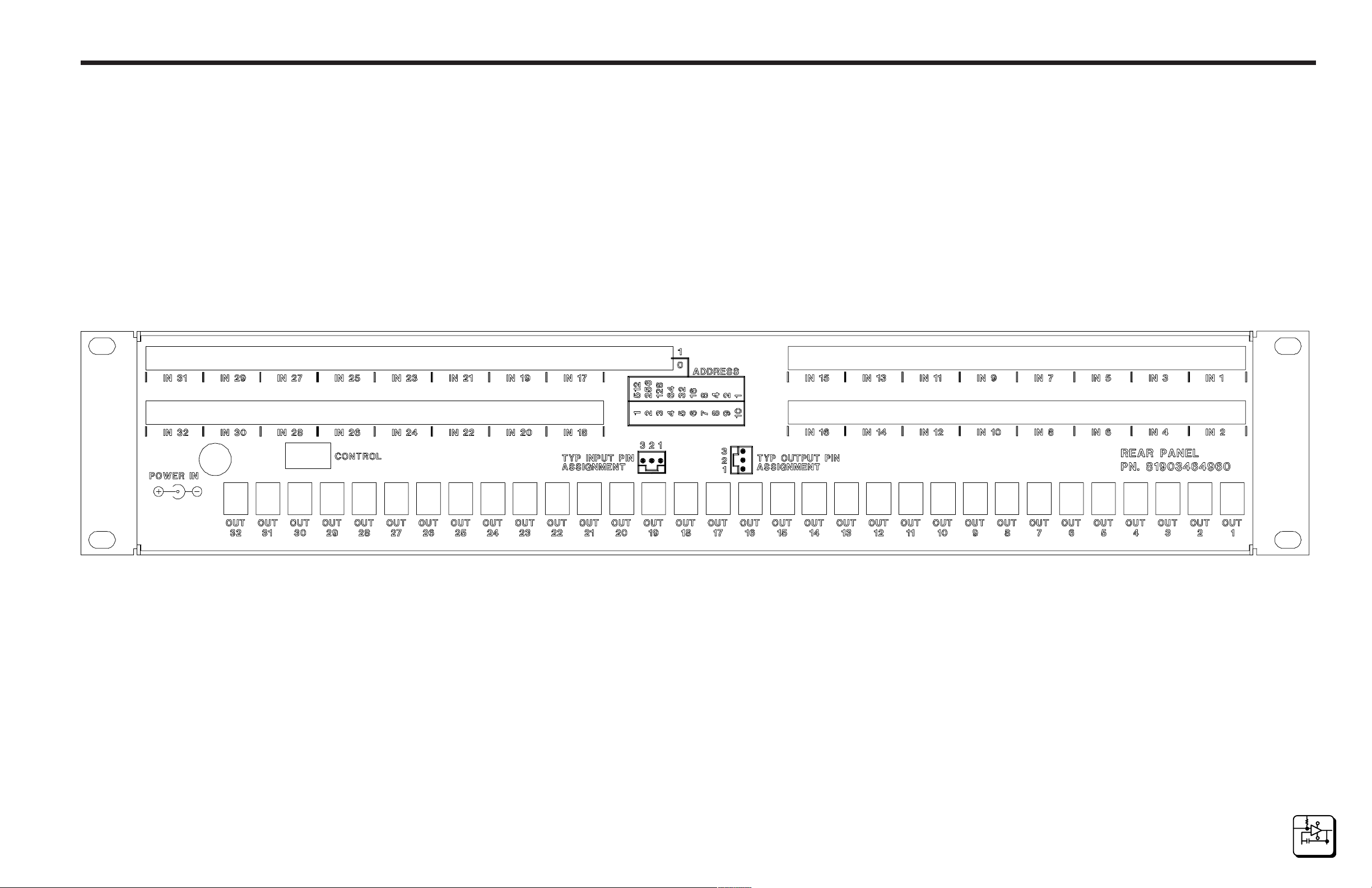
RCP-GPIO Control Panel
Schematics Section 6
10/96
P/N 81905903860
RCP-GPIO Control Panel Rear View
page 6.3
6
SCHEMATICS
Page 36
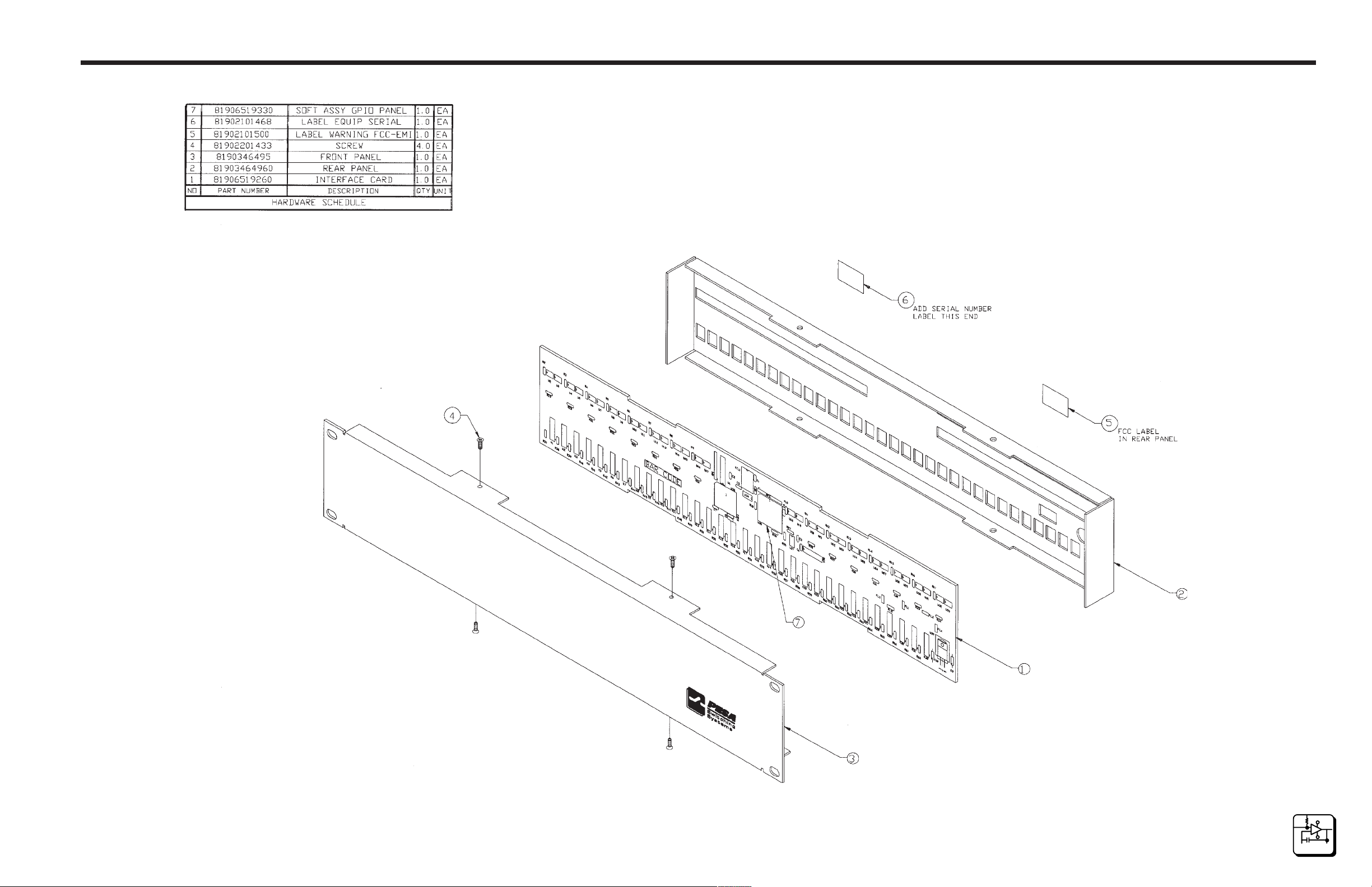
RCP-GPIO Control Panel
Schematics Section 6
10/96
P/N 81905903860
Configuration Drawing RCP-GPIO Control Panel Assembly CD63-0784
page 6.4
6
SCHEMATICS
Page 37
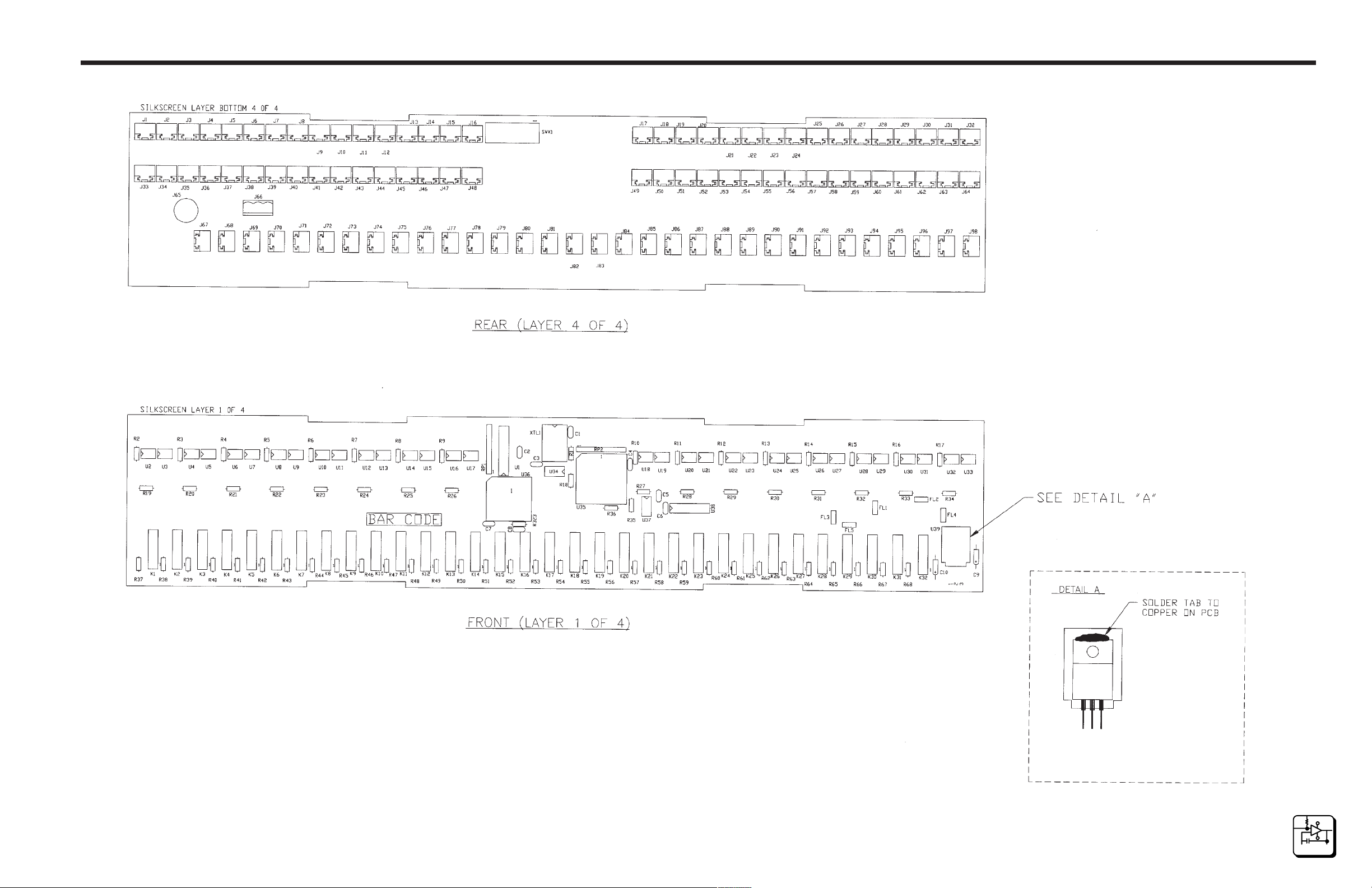
RCP-GPIO Control Panel
Schematics Section 6
10/96
P/N 81905903860
Component Assembly RCP-GPIO Interface Card CA25-1376
page 6.5
6
SCHEMATICS
Page 38
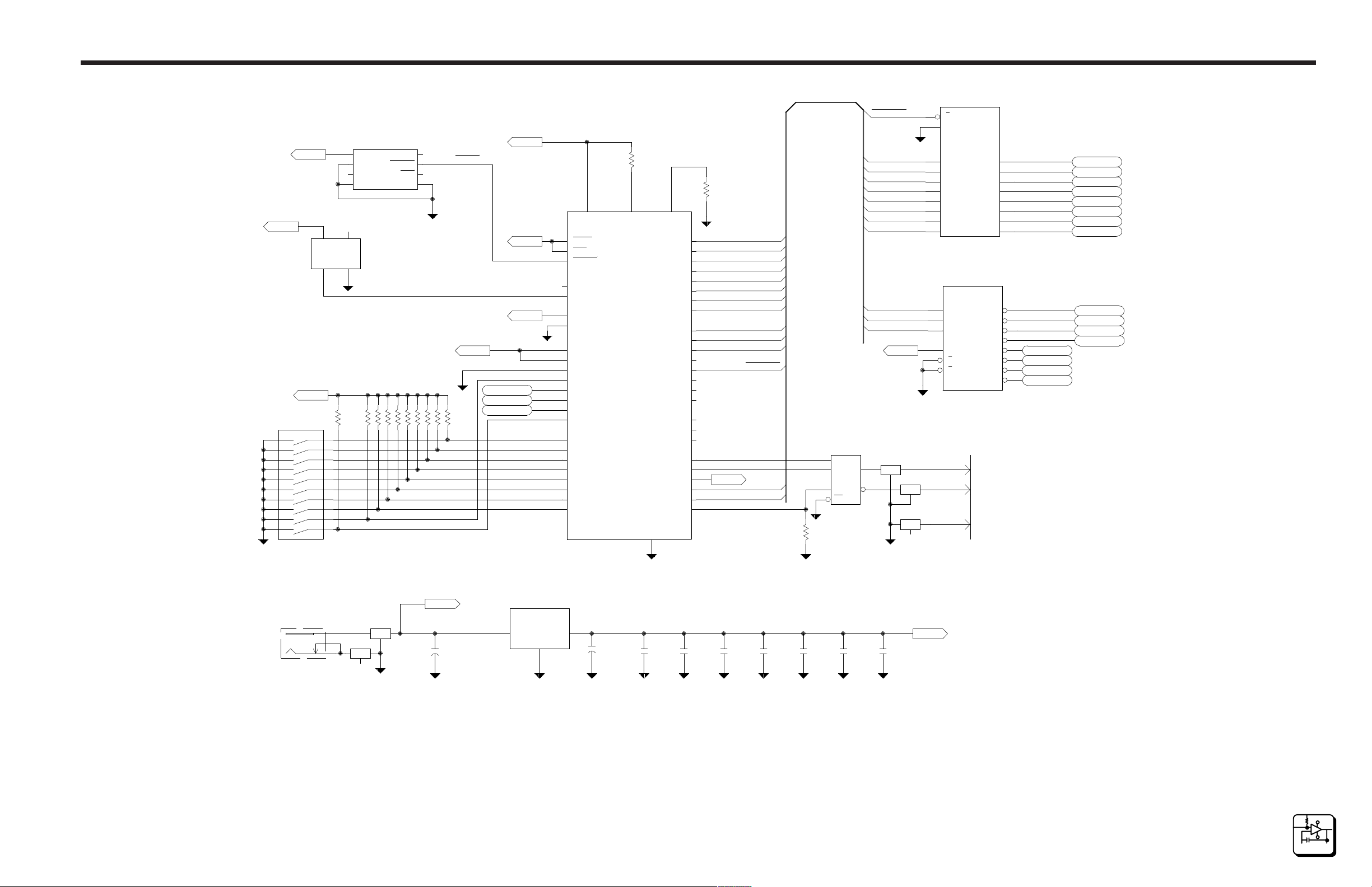
RCP-GPIO Control Panel
Schematics Section 6
+5V
12
13
14
15
16
17
18
19
20
DIPSWX10
ADDRESS
+5V
SWX1
PANEL
14
VCC
OUT VSS
+5V
1011
9
8
7
6
5
4
3
2
1
2
8
6
4
IN
R36
4.7K
VCC
VBATT
WDI
PFI
1
7.3728MHz
78
U34
MAX690
XTL1
1
1
2
3
VOUT
RESET
PFO
VSS
SIP10
SIP10
SIP10
SIP10
SIP10
SIP10
SIP10
SIP10
SIP10
1
1
5
4
FL3
FL5
19
1
2
3
4
5
6
7
8
9
1
2
3
6
4
5
G
DIR
74HC245
A1
A2
A3
A4
A5
A6
A7
A8
74HC138
A
B
C
G1
2AG
2BG
J66
J66
J66
U1
U38
B1
17
Y0
Y1
Y2
Y3
Y4
Y5
Y6
Y7
COMA
COMB
16
15
14
13
12
11
15
14
13
12
11
10
9
7
KB_COL1
KB_COL2
KB_COL3
KB_COL4
KB_COL5
KB_COL6
KB_COL7
KB_ROW0
KB_ROW1
KB_ROW2
KB_ROW3
KB_ROW4KB_ROW4
KB_ROW5
KB_ROW6
KB_ROW7
B2
B3
B4
B5
B6
B7
B8
1
3
2
SHEET 3
SHEET 3
SHEET 3
SHEET 3
SHEET 3
SHEET 3
SHEET 3
SHEET 3
SHEET 3
SHEET 3
SHEET 3
SHEET 3
NOT USED
NOT USED
NOT USED
NOT USED
KB_COL0
18
KBD_SEL
DSP_SEL
DSP_RS
DSP_RW
+5V
+5V
+5V
18
XIRQ
19
IRQ
17
RESET
8
XTAL
7
EXTAL
52
VRH
51
VRL
34
PA0/IC3
33
PA1/IC2
32
PA2/IC1
31
PA3/OC5/OC1
30
PA4/OC4/OC1
29
PA5/OC3/OC1
28
PA6/OC2/OC1
27
PA7/PAI/OC1
43
PE0/AN0
45
PE1/AN1
47
PE2/AN2
49
PE3/AN3
44
PE4/AN4
46
PE5/AN5
48
PE6/AN6
PE7/AN7
R18
1K
26 2 3
PC0/AD0
PC1/AD1
U35
68HC11
PC2/AD2
PC3/AD3
PC4/AD4
PC5/AD5
PC6/AD6
PC7/AD7
PB2/A10
PB3/A11
PB4/A12
PB5/A13
PB6/A14
PB7/A15
STRA/AS
STRB/RW
PD0/RXD
PD1/TXD
PD2/MISO
PD3/MOSI
PD4/SCK
VSS
MODAMODB/STBYVDD
PB0/A8
PB1/A9
PD5/SS
1
E
R1
1K
9
10
11
12
13
14
15
16
42
41
40
39
38
37
36
35
4
6
5
RXD
20
TXD
21
22
23
24
TX_ENABLE
2550
+5V
KBD_SEL
LDATA
LCLK
D0
D1
D2
D3
D4
D5
D6
D7
A0
A1
A2
R35
1K
1
4
3
2
U37
R
D
DE
RE
75ALS176
D0
D1
D2
D3
D4
D5
D6
D7
A0
A1
A2
+5V+5V
6
FL1
A
7
B
1
7
5
3
1
1
6
7
RESET
SYSCLK
1
1
1
RP2
RP2
RP2
RP2
RP2
RP2
RP2
RP2
RP2
4.7K
4.7K
4.7K
4.7K
4.7K
4.7K
4.7K
4.7K
4.7K
8
9
10
10/96
P/N 81905903860
J65
1
2
3
FL2
BOARD ID CODE : 3 PA0 = 1*
PA1 = 1
PA2 = 0
FL4
Vext
+
C10
10uF,20V
U39
LM7805
1
GND
3
OUTIN
2
+
C9
10uF,20V
C4
0.1uf
0.1uFC20.1uF
C1
C7
0.1uF
C6
0.1uF
C5
0.1uF
Schematic (Sheet 1 of 3) RCP-GPIO Interface Card SC33-1376
C3
0.1uF
+5V
page 6.6
6
SCHEMATICS
Page 39
RCP-GPIO Control Panel
Schematics Section 6
SHEET 1
SHEET 1
+5V
3.3K
0.001uF
R323
C8
LDATA
LCLK
25
DATA
24
CLOCK
26
ENABLE
21
BRIGHTNESS
1
N/C
12
N/C
23
N/C
34
N/C
U36
MM5450V
O10
O11
O12
O13
O14
O15
O16
O17
O18
O19
O20
O21
O22
O23
O24
O25
O26
O27
O28
O29
O30
O31
O32
O33
O34
OUT 1
J98
R37
VEXT
220
R38
VEXT
220
R39
VEXT
R67
220
R68
220
220
R66
220
1
3
2
1
3
2
1
3
2
20
O1
19
O2
18
O3
17
O4
16
O5
15
O6
14
O7
13
O8
11
O9
10
9
8
7
6
5
4
3
44
43
42
41
40
39
38
37
36
35
33
32
31
30
29
28
27
VEXT
VEXT
VEXT
3
J98
3
5
7
J98
2
OUT 2
J97
1
1
3
J97
3
5
J97
7
2
J96
1
1
3
J96
3
5
7
J96
2
J69
OUT 30
1
3
J69
5
7
J69
OUT 31
J68
1
3
J68
5
J68
7
OUT 32
J67
1
3
J67
5
J67
7
1
1
DSS41
DSS41
DSS41
DSS41
DSS41
DSS41
K1
K2
K3
OUT 3
K30
K31
K32
VEXT
VEXT
VEXT
VEXT
VEXT
VEXT
R64
R63
220
220
R65
220
R40
220
R41
220
R42
220
1
3
2
1
3
2
1
3
2
1
3
2
1
3
2
1
3
2
J72
J72
J72
J71
J71
J71
J70
J70
J70
J95
J95
J95
J94
J94
J94
J93
J93
J93
1
3
5
7
1
3
5
7
1
3
5
7
OUT 4
1
3
5
7
OUT 5
1
3
5
7
OUT 6
1
3
5
7
OUT 27
DSS41
OUT 28
DSS41
OUT 29
DSS41
DSS41
DSS41
DSS41
K27
K28
K29
OUT 7
R61
220
220
R43
220
R44
220
R45
220
R60
220
R62
J92
1
1
3
J92
3
5
J92
7
2
OUT 8
J91
1
1
3
J91
3
5
J91
7
2
OUT 9
J90
1
1
3
J90
3
5
J90
7
2
OUT 24
J75
1
1
3
J75
3
5
7
J75
2
OUT 25
J74
1
1
3
J74
3
5
7
J74
2
OUT 26
J73
1
1
3
J73
3
5
7
J73
2
DSS41
DSS41
DSS41
DSS41
DSS41
DSS41
K24
K25
K26
K7
VEXT
K8
VEXT
K9
VEXT
VEXT
VEXT
VEXT
220
R58
220
R59
220
R57
R47
220
R48
220
R46
220
1
3
2
1
3
2
1
3
2
1
3
2
1
3
2
1
3
2
K4
VEXT
K5
VEXT
K6
VEXT
VEXT
VEXT
VEXT
OUT 10
J89
1
3
J89
5
J89
7
OUT 11
J88
1
3
J88
5
J88
7
OUT 12
J87
1
3
J87
5
J87
7
OUT 21
J78
1
3
J78
5
7
J78
OUT 22
J77
1
3
J77
5
7
J77
OUT 23
J76
1
3
J76
5
7
J76
DSS41
DSS41
DSS41
DSS41
DSS41
DSS41
K21
K22
K23
K10
K11
K12
VEXT
VEXT
VEXT
VEXT
VEXT
VEXT
VEXT
VEXT
R55
220
R56
220
R51
R54
220
R49
220
R50
220
220
R52
220
R53
220
1
3
2
1
3
2
1
3
2
1
3
2
1
3
2
1
3
2
1
3
2
1
3
2
OUT 13
J86
1
3
J86
5
J86
7
OUT 14
J85
1
3
J85
5
J85
7
OUT 15
J84
1
3
J84
5
J84
7
OUT 16
J83
1
3
J83
5
7
J83
OUT 17
J82
1
3
J82
5
7
J82
OUT 18
J81
1
3
J81
5
7
J81
OUT 19
J80
1
3
J80
5
7
J80
OUT 20
J79
1
3
J79
5
7
J79
K13
DSS41
K14
DSS41
K15
DSS41
K16
DSS41
K17
DSS41
K18
DSS41
K19
DSS41
K20
DSS41
10/96
P/N 81905903860
Schematic (Sheet 2 of 3) RCP-GPIO Interface Card SC33-1376
page 6.7
6
SCHEMATICS
Page 40
RCP-GPIO Control Panel
SHEET 1
KB_COL0
KB_COL1
KB_COL2
KB_COL3
KB_COL4
KB_COL5
KB_COL6
KB_COL7
RP1
+5V
12
4.7K
SHEET 1 SHEET 1 SHEET 1 SHEET 1
SHEET 1
RP1
+5V
13
4.7K
SHEET 1
SHEET 1
SHEET 1
SHEET 1
SHEET 1
SHEET 1
+5V
+5V
+5V
+5V
+5V
+5V
RP1
14
4.7K
RP1
15
4.7K
RP1
16
4.7K
RP1
17
4.7K
RP1
18
4.7K
RP1
19
4.7K
RP1
110
4.7K
5
4
5
4
5
4
5
4
5
4
5
4
5
4
5
4
4N33
4N33
4N33
4N33
4N33
4N33
4N33
4N33
Schematics Section 6
R2
+5V
6
1
2
3
U2
+5V
6
1
2
3
U3
+5V
6
1
2
3
U4
+5V
6
1
2
3
U5
+5V
6
1
2
3
U6
+5V
6
1
2
3
U7
+5V
6
1
2
3
U8
+5V
6
1
2
3
U9
J32
1
390
J32
2
J32
3
J31
1
J31
2
R19
390
390
R20
390
390
R21
390
R22
390
INPUT 1
3
J64
1
2
3
1
2
INPUT 2
3
R3
J30
1
2
3
1
2
INPUT 3
3
J62
1
2
3
1
2
INPUT 4
3
R4
J28
1
2
3
1
2
INPUT 5
3
J60
1
2
3
1
2
INPUT 6
3
R5
J26
1
390
2
3
1
2
INPUT 7
3
J58
1
2
INPUT 8
3
J57
1
2
3
J31
J64
J64
J63
J63
J63
J30
J30
J29
J29
J29
J62
J62
J61
J61
J61
J28
J28
J27
J27
J27
J60
J60
J59
J59
J59
J26
J26
J25
J25
J25
J58
J58
J57
J57
KB_ROW1KB_ROW0 KB_ROW2
5
4
5
4
5
4
5
4
5
4
5
4
5
4
5
4
4N33
4N33
4N33
4N33
4N33
4N33
4N33
4N33
6
3
U10
6
3
U11
6
3
U12
6
3
U13
6
3
U14
6
3
U15
6
3
U16
6
3
U17
+5V
1
2
+5V
1
2
+5V
1
2
+5V
1
2
+5V
1
2
+5V
1
2
+5V
1
2
+5V
1
2
R6
J24
1
390
J24
2
J24
3
J23
1
J23
2
INPUT 9
J23
3
R23
J56
1
390
J56
2
J56
3
J55
1
J55
2
INPUT 10
J55
3
R7
1
J22
390
J22
2
J22
3
J21
1
J21
2
INPUT 11
J21
3
R24
J54
1
390
J54
2
J54
3
J53
1
J53
2
INPUT 12
J53
3
R8
J20
1
390
J20
2
J20
3
J19
1
J19
2
INPUT 13
J19
3
R25
J52
1
390
J52
2
J52
3
J51
1
J51
2
INPUT 14
J51
3
R9
J18
1
390
J18
2
J18
3
J17
1
J17
2
INPUT 15
J17
3
R26
J50
390
J50
J50
J49
J49
1
2
3
1
2
INPUT 16
J49
3
4N33
6
5
4
3
U18
4N33
6
5
4
3
U19
4N33
6
5
4
3
U20
4N33
6
5
4
3
U21
4N33
6
5
4
3
U22
4N33
6
5
4
3
U23
4N33
6
5
4
3
U24
4N33
6
5
4
3
U25
+5V
1
2
+5V
1
2
+5V
1
2
+5V
1
2
+5V
1
2
+5V
1
2
+5V
1
2
+5V
1
2
R10
J16
1
390
J16
2
J16
3
J15
1
J15
2
INPUT 17
J15
3
R27
J48
1
390
J48
2
J48
3
J47
1
J47
2
INPUT 18
J47
3
R11
J14
1
390
J14
2
J14
3
J13
1
J13
2
INPUT 19
J13
3
R28
J46
1
390
J46
2
J46
3
J45
1
J45
2
INPUT 20
J45
3
R12
J12
1
390
J12
2
J12
3
J11
1
J11
2
INPUT 21
J11
3
R29
J44
1
390
J44
2
J44
3
J43
1
J43
2
INPUT 22
J43
3
R13
J10
1
390
J10
2
J10
3
J9
1
J9
2
INPUT 23
J9
3
R30
J42
1
390
J42
2
J42
J41
J41
INPUT 24
3
J41
1
2
KB_ROW3
3
4N33
6
5
4
3
U26
4N33
6
5
4
3
U27
4N33
6
5
4
3
U28
4N33
6
5
4
3
U29
4N33
6
5
4
3
U30
4N33
6
5
4
3
U31
4N33
6
5
4
3
U32
4N33
5
4
+5V
6
1
2
3
U33
+5V
1
2
+5V
1
2
+5V
1
2
+5V
1
2
+5V
1
2
+5V
1
2
+5V
1
2
J33
J34
J34
J33
J40
J40
J39
J39
J39
J38
J38
J37
J37
J37
J4
J36
J36
J35
J35
J35
J2
J1
J1
J1
R34
390
2
INPUT 32
3
1
2
R14
J8
2
3
1
2
3
2
3
1
2
3
2
3
1
2
3
2
3
1
2
3
2
3
1
2
3
2
3
1
2
3
2
3
1
2
3
J33
INPUT 25
J40
INPUT 26
J6
INPUT 27
J38
INPUT 28
J4
INPUT 29
J36
INPUT 30
J2
INPUT 31
1
3
1
1
1
1
1
1
1
390
J8
J8
J7
J7
J7
R31
390
R15
390
J6
J6
J5
J5
J5
R32
390
R16
390
J4
J3
J3
J3
R33
390
R17
390
J2
J34
10/96
P/N 81905903860
Schematic (Sheet 3 of 3) RCP-GPIO Interface Card SC33-1376
page 6.8
6
SCHEMATICS
Page 41

RCP-GPIO
7.1 Parts List
General
The Parts List in this section have been grouped according to each assembly associated with the RCP-GPIO Control Panel. Refer to each list by
name of card, board, or section of the equipment requiring replacement
parts.
Part Part Number Page
RCP-GPIO Control Panel Assembly 81906519250 7.2
RCP-GPIO Interface Card 81906519260 7.3
RCP-GPIO Software 81906519330 7.4
Parts List Section 7
10/96
P/N 81905903860
page 7.1
7
PARTS LISTS
Page 42

RCP-GPIO
Section 7Parts List
RCP-GPIO Control Panel Assembly - 81906519250
81902101468 LABEL EQUIPMENT SERIALIZATION 1 EA
81902101500 LABEL WARNING FCC-EMI 1 EA
81902201433 SCREW 4-40X3/16 FLAT HEAD PHIL 4 EA
81902907800 CONN 3-POS W/STRAIN RELIEF 1 EA
81902908110 CONN 3-PIN F STRAIN RELIEF 96 EA
81903464950 RCP-GPIO FRONT PANEL 1 EA
81903464960 RCP-GPIO REAR PANEL 1 EA
81906519260 RCP-GPIO INTERFACE CARD 1 EA
81906519330 SOFT ASSY RCP-GPIO PANEL 1 EA
CD63-0784 DOC RCP-GPIO CONFIGURATION REF
7
PARTS LISTS
page 7.2
10/96
P/N 81905903860
Page 43

RCP-GPIO
Parts List Section 7
RCP-GPIO Interface Card - 81906519260
81900200502 RESISTOR 220 OHM 5% 1/4W R37-R68 32 EA
81900200569 RESISTOR 390 OHM 5% 1/4W R2-R17 R19-R34 32 EA
81900200668 RESISTOR 1K 5% 1/4W R1 R18 R35 3 EA
81900200783 RESISTOR 3.3K 5% 1/4W R323 1 EA
81900200825 RESISTOR 4.7K 5% 1/4W R36 1 EA
81900600958 SIP 4.7K 10-PIN 9 RESISTOR RP1 RP2 2 EA
81900700055 CAP 0.1MF 50V CERAMIC RADIAL C1-C7 7 EA
81900700238 CAP 0.001MF 1000V CERAMIC C8 1 EA
81900900291 CAP 10MF 20V TANTLM AXIAL C9 C10 2 EA
81901601187 REG MC7805C +5V 1A TO-220 U39 1 EA
81901602318 IC 4N33 OPTO DARLINGTON OUT U2-U33 32 EA
81901604314 IC 74HC245 CMOS BUS TRANSV U1 1 EA
81901604827 IC 1 OF 8 DECODER/MULTIPLXR U38 1 EA
81901606061 IC MAX690CPA PWR SUP MON U34 1 EA
81901606830 IC 7.3728 MHZ OSCILLATOR XTL1 1 EA
81901606870 IC 5450 34 SEG LED DRIVER U36 1 EA
81901606880 IC 74ALS176 RS485 TRANSCV U37 1 EA
81901800200 RELAY SIP 5VDC K1-K32 32 EA
81902105050 LABEL BARCODE 1.5"X0.25" 1 EA
81902413760 RCP-GPIO INTERFACE CARD 1 EA
81902600543 SWITCH 10-POS DIP PC-MT SWX1 1 EA
81902905991 SOCKET 52-PIN PLCC PC-MT REF: U35 1 EA
81902906353 CONN 3-POS MALE POLAR STR J66 1 EA
81902907400 CONN SOCKET PLCC 44-PIN REF: U36 1 EA
81902907460 CONN POWER JACK PCB MOUNT J65 1 EA
81902908100 CONN 3-PIN PC-MT VERTICAL J1-J64 J67-J98 96 EA
81903900740 FILTER EMI SUPPRESSION FL1-FL5 5 EA
CA25-1376 DOC RCP-GPIO INTERFACE CARD REF
DD52-1376 DOC RCP-GPIO INTERFACE CARD REF
SC33-1376 DOC RCP-GPIO INTERFACE CARD REF
10/96
P/N 81905903860
page 7.3
7
PARTS LISTS
Page 44

RCP-GPIO
Section 7Parts List
RCP-GPIO Software Assembly - 81906519330
81901606730 IC 68HC11E9 SINGLE CHIP 1 EA
81902104930 LABEL WHITE 1/2"X3/4" REC 1 EA
81905603520 SOFT BIOS RCP-GPIO REF
81906203230 DOC PROGRAMMING EPROMS REF
7
PARTS LISTS
page 7.4
10/96
P/N 81905903860
 Loading...