

Page 1
I
NTEGRITY
CS S
ERIES
S
TART
A2HD516 P
ROCESSOR
UNPACK THE
Step
1
PROCESSOR RACK UNIT
Carefully unpack your Integrity CS Unit from shipping container
and verify package contents against contents listed below.
Visually inspect the unit for any signs of damage in shipment or
transit.
If any components are missing or damaged, contact QuStream
Customer Service.
1
P
U
NPACK
S
HIPPI NG
C
ONTAINER
ACKAG E CONTENTS
P
OWER
C
ORD
MATING AUDI O
CONNECTORS
(A
TTACH ED TO REAR
PANEL AU DIO
CONN ECTORS
C
J
C
)
OAXIAL
UMPER
ABLE
Q
:
E
THER NET
(RJ45)
J
UMPER
C
ABLE
UICK START
G
UIDE
Quick-Start Guide
Step
R
EAR PANEL LAYOUT
2
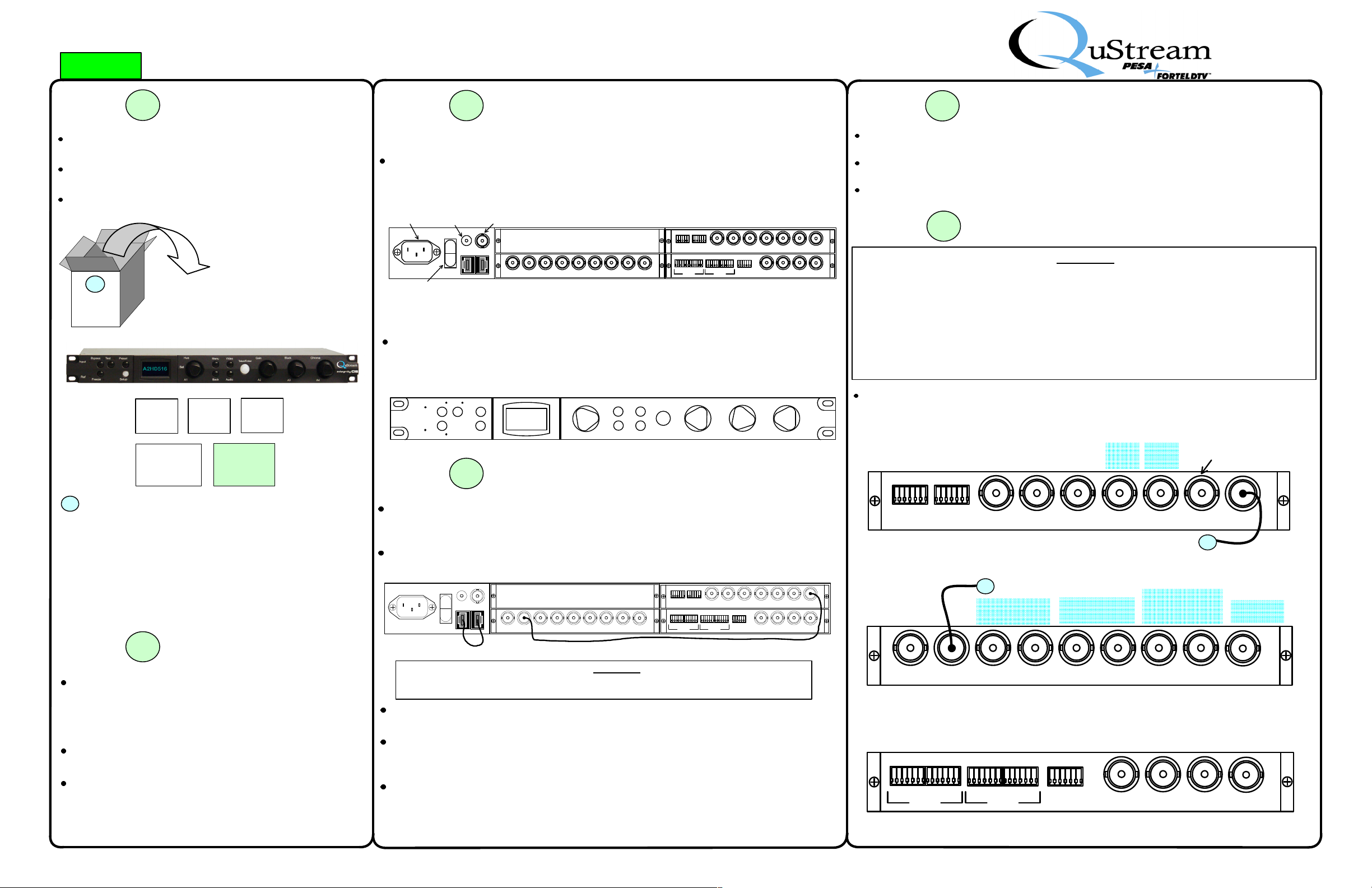
Your Integrity CS A2HD516 is composed of a 1RU rack frame with a power supply and three
processing modules, installed in card slots on the rear of the chassis. An illustration of the rear
panel layout is shown below.
MAIN POWER
CONNECTOR
POWER
SWITCH
F
RONT PANEL LAYOUT
REDUNDANT
POWER
CONNECTOR
ETHERNET
CONNECTORS
In most installations, the processor control panel is installed directly to the chassis frame. If
your system is equipped with the remote panel option, a blank front panel with status LEDs is
attached to the chassis. Whether local or remote, the control panel layout is as shown in the
illustration below.
Bypass T est
Inpu t
Ref
Freeze
Step
3
GET ACQUAINTED (CONT.)
EXTERNAL
SYNC
CONNECTOR
IN 1 OUT 1A OUT 1B OUT 2A OUT 2B OPTION BOPTION A GEN LKIN 2
FORMAT CONVERTER MODUL E
Preset
Setup
Hue
Sel
A1
Video
Menu
Back Audio
Take/Enter
INSTALL REAR PANEL JUMPERS
FRAME SYNC MODULE
ANALOG AU DIO 1,2,3,4
CH1 CH2 CH3 CH4 CH1 CH2 CH3 CH4
ANALOG IN
(1,2,3,4) AUX 1/2 IN 1/2 OUT3/4 IN 3/ 4 OUT
Gain
A2
AES B
AES A
ANALOG OUT
(1,2,3,4)
AUDIO MODULE
Black
A3
DL
DL
VID A SDI IN OUT 1VID B OU T 2
AES
REF
AES
Chroma
A4
Step
4
MOUNT A2HD516 CHASSIS FRAME
Considerations for mounting location include proximity to signal sources/destinations, availability
of primary power and availability of a source of external sync.
Mount the chassis frame in an equipment rack and secure frame to rack using four rack mount
screws.
Do not apply power until all external connections are made and verified.
Step
5
VIDEO/AUDIO CONNECTIONS
!! NOTE !!
Your A2HD516 Processor is shipped from the factory with the UDC operating mode selected.
This mode allows the processor to function as an analog or SD-SDI to HD converter
WITHOUT using the included side column keyer function.
If you wish to use the side column keyer, you MUST provide an HD input signal for use as the
keyer insert video source, and you MUST change the processor to the UCP operating mode as
shown in Step 8 of this guide. If UCP is selected as the operating mode and an HD signal is
not applied to the key video input connector, the A2HD516 WILL NOT function properly!!
Complete video and audio connections to the A2HD516 using the diagrams below as a
reference. Highlighted connection points indicate major function connections.
F
RAME SYNC MODULE CONNECTIONS
ANALO G AUDIO
INPUTS 1 & 2
ANAL OG AUDIO
INPUTS 3 & 4
AES 1
INPUT
AES 2
INPUT
AES 3/
DOLBY-E
INPUT
SD-SDI
SIGNAL
INPUT
ANA LOG
SIGNAL
INPUT
SD-SDI OUTPUT OF
CONVERTED A NALOG
SIGNAL
2
If any components are missing or damaged, contact QuStream
Customer Service by phone or e-mail.
Customer Service: 1+ (256) 726-9222
Toll Free: (800) 323-7372 (US and Canada)
Fax: 1+ (256) 726-9268
Email: [email protected]
Step
The Integrity CS A2HD516 is a self-contained format converter
V
ERIFY ALL ITEMS SHOWN ABOVE ARE
I
NCLUDED WITH UNIT
2
GET ACQUAINTED
Your Integrity CS Series processing product requires installation of rear panel jumpers for proper
operation. These jumper cables are removed for shipping, but are included in the package with
the processor.
Refer to the following figure, and perform the steps to install these necessary jumper cables prior
to use of the processor.
SUPPLIED ETHERNET
CABLE JUMPER
IN 1 OUT 1A
OUT 1B OUT 2A OUT 2B
ANALOG AUDIO 1,2,3,4
CH1 CH2 CH3 CH4 CH1 CH2 CH3 CH4
OPTION BOPTION A GENLOCKIN 2
AES A AES B
DL
DL
ANALOG IN
ANALOG OUT
(1,2,3,4) AUX 1/2 IN 1/ 2 OUT3/4 IN 3/4 OUT
(1,2,3,4)
SUPPLIED COAX IAL
CABLE JUMPER
VID A SDI IN
AES
REF
AES
VID B
OUT 2
OUT 1
!! NOTE !!
Your Integrity CS Processor WILL NOT function unless these connections are completed.
ANALOG A UDIO 1,2,3,4
F
ORMAT CONVERTER CONNECTIONS
SIDE COLUMN
KEYER VIDEO
INPUT
(SEE NOTE
ABOVE)
IN 1
IN 2
AES A AES B
COAX JUMPER FROM
FRAME SYNC MODULE
A
HD-SDI
OUTPUTS
1 2
OUT 1A OUT 1B OUT 2A OUT 2B OPTION BOPTION A GENLOCK
VID A SDI IN
COAX JUMPER TO FORMAT
CONVERTER MODULE
SD-SDI
OUTPUTS
1 2
VID B
OUT 1
A
JUMPER SELECT
SD-SDI or ANALOG
OUTPUTS
1 2
OUT 2
EXTERNAL
SYNC INPUT
and audio embedder/de-embedder. It accepts an input of
composite (NTSC/PAL) analog video or SD-SDI digital video
and produces outputs of HD-SDI, SD-SDI and option outputs
selectable as SD-SDI or composite analog.
The included side-column keyer accepts an input of HD SDI
video.
Inputs are provided for both AES and analog audio sources for
embedding. De-embedded audio is available as both AES
pairs and analog, selectable from any de-embedded channel
Locate supplied coaxial cable jumper and supplied Ethernet cable jumper shipped with your
Integrity processor.
Install coaxial jumper between connector labeled Output (OUT) 2 on frame sync module and
connector labeled Input (IN) 2 on format converter module. Refer to figure when installing this
cable.
If you are using the LOCAL control panel on the front of the frame to control this unit, install
Ethernet cable jumper between the two Ethernet (RJ45) port connectors on rear panel of
processor. If you are using a REMOTE control panel over the facility LAN, use an Ethernet switch
or hub to provide an active network connection to BOTH rear panel Ethernet ports.
A
UDIO MODULE CONNECTIONS
CH4
ANAL OG AUDIO
OUTPUTS
1 & 2 3 & 4
CH1 CH2 CH3
ANA LOG OUT
(1,2,3,4)
ANALO G AUDIO
INPUTS
5 & 6 7 & 8
CH1 CH2 CH3
ANALOG I N
(1,2,3,4)
CH4
AES
DL
DL
REF
AUX 1/2 IN
AES
AES 4
INPUT
AES 5
INPUT
3/4 IN 3/4 OUT
AES 1
OUTPUT
1/2 OUT
AES 2
OUTPUT
Audio Module Connector Pin-Outs Shown on Next Page
Part No. 81-9059-0647-0 Rev. B
Page 2
I
NTEGRITY
CS S
A2HD516 P
ERIES
ROCESSOR
Quick-Start Guide
Step
A
NALOG AUDIO CONNECTORS
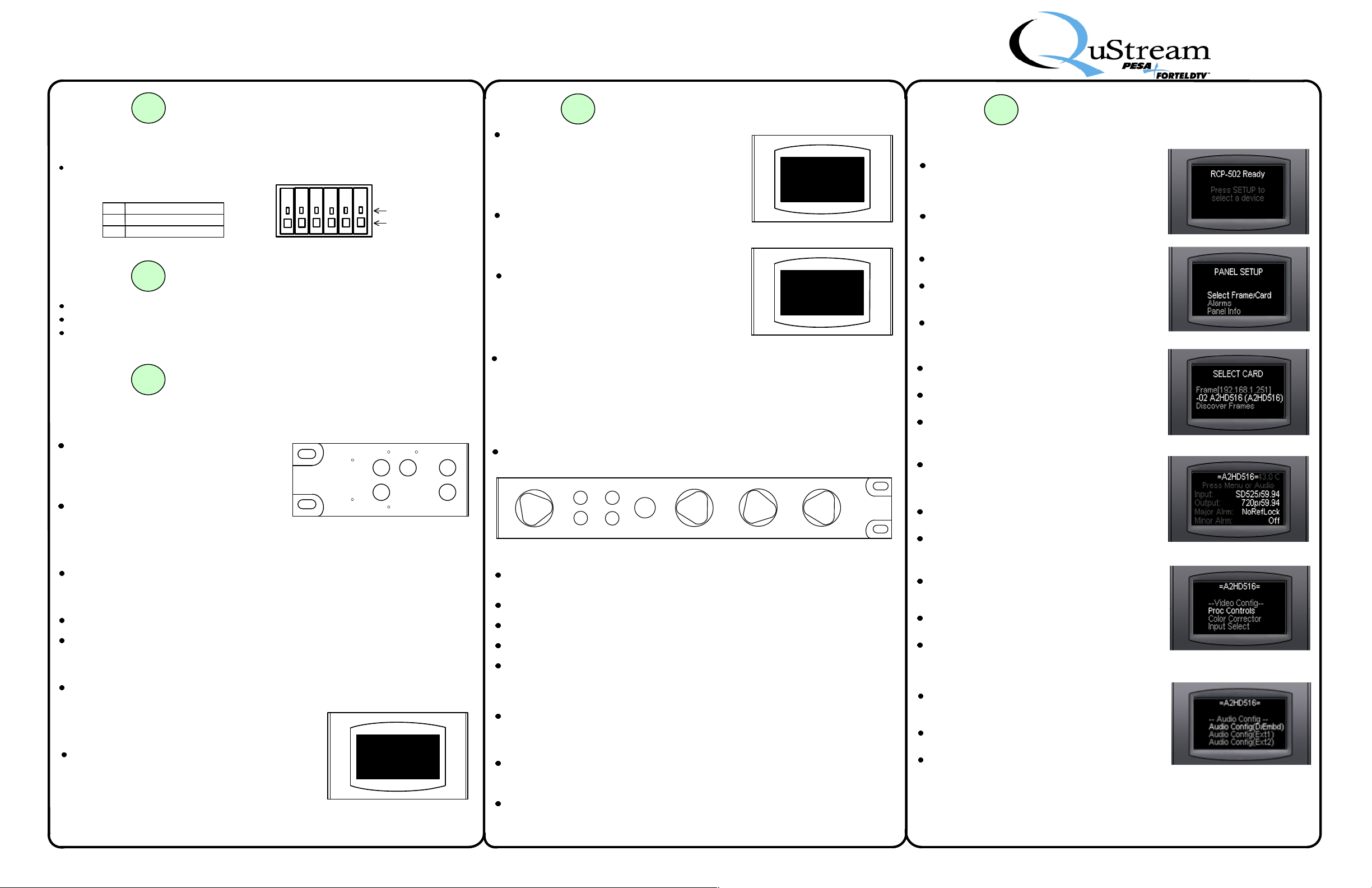
The illustration and chart identify pin-out
for a typical 6-pin analog audio connector.
Pin
Function
Positiv e Audio Signa l
+
Shield
G
Nega tive Audio Signal
-
Step
Inspect all connections to the processor. Ensure that all cables are installed securely.
Attach power cord to rear panel main power connector and a source of power.
Move power switch to the “ON” position.
Step
C
ONTROL PANEL LAYOUT AND OPERATION
Direct Entry Pushbuttons
Test – Pressing Test switches output signal
from active video source to a user-selectable
test signal. A second pressing cancels test
output and returns to video source. The Test
LED illuminates when test output is active.
Freeze – Pressing Freeze freezes video
output signal based on a user-selectable
freeze frame type. A second pressing
cancels freeze output and returns to video
source. The Freeze LED illuminates when
freeze function is active.
Setup – Setup causes control panel to access system set-up menu regardless of
which menu screen is currently displayed.
System Status Indicators
Input – The Input LED illuminates if video input signal is lost for any reason.
Reference (Ref) – The Ref LED illuminates if genlock reference source is lost for any
reason.
Bypass and Preset
Bypass and Preset pushbuttons and Bypass LED are not used in current configuration
of processor.
Menu Display Screen
Menus, operational parameters and system status
are displayed on a six line screen, as illustrated.
VIDEO/AUDIO CONNECTIONS (CONT.)
5
SUPPLIED MATING
AUDIO CONNECTOR
+ G - + G -
6
7
INITIAL POWER UP
BASIC OPERATION
Input
Ref
Bypass Test
Freeze
Text Line 1
Text Line 2
Text Line 3
Text Line 4
Text Line 5
Text Line 6
WIRE RELEASE
WIRE SLOT
Preset
Setup
Step
Menus are arranged in a tree structure, and in
many instances, selecting an item brings up a
branch menu with additional entries. Often a
menu page has more items than can be shown on
the display lines. To navigate these menus, use
selector (SEL) knob to right of display to scroll
through entries until desired entry is highlighted.
Underscore marks before and after text identify a
text entry that describes the function of the menu
items below it. Example: –Video Config
indicates scroll list under entry contains menu
selection options for video configuration function.
Data entry screens allow changes to operating
parameters or adjustments to system settings.
Integrity CS menu structure uses a highlighted
entry to indicate a selectable function modifiable
value. In the example shown here, the value of
all four entries are highlighted, and can be
changed as desired.
Values and parameters are modified by selecting new value or selection from a
scrolling list of available options, or increasing/decreasing numerical values, by
using rotary knobs on control panel. Data entry screens have a maximum of four
selectable values or functions, each is software mapped to one control knob,
beginning with knob A1 for first selectable entry and continuing in sequence to knob
A4 for fourth selectable entry. In this example, HUE vector may be selected by
rotating control knob A1, GAIN percentage by rotating knob A2, BLACK level by
rotating A3 and CHROMA percentage by rotating A4.
Pushbuttons and rotary controls located to right of display screen navigate menu
screens and select or modify parameters.
Hue
Sel
A1
Function Select Pushbuttons
Menu – Pressing Menu advances to next level of menu tree structure as
determined by highlighted menu screen selection.
Back – Pressing Back causes previous menu to be recalled.
Video – Pressing Video accesses top level video status screen.
Audio – Pressing Audio accesses top level audio configuration menu.
Take/Enter – When Take/Enter pushbutton is illuminated green, it is “live” and
used in the current menu to execute a function or command. Once commands is
executed, LED in button extinguishes. Take/Enter performs a function only when
illuminated green.
Some menus use Function Pushbuttons to execute commands on screen. Any
button press required is prompted on individual menus.
Rotary Controls
A1 (Sel) – The Select (Sel) control, also labeled A1, scrolls through menu entries
on scrollable screens. On data entry screens, A1 selects commands or values for
entry mapped to it.
7
Menu Video
Back Audio
BASIC OPERATION (CONT.)
=A2HD516=
Video Config
--
Proc Controls
Color Corrector
Input Select
–
=A2HD516=
Video Out Proc Controls
HUE
GAIN
BLACK
CHROMA
Take/Enter
Gain
A2
Black
Chroma
A3
A4
--
0.0 deg
100.0 %
0 mV
100.0 %
Step
S
YSTEM INITIALIZATION
On power-up, a system initialization bootup procedure commences. Upon
completion of initialization, the screen
message shown here is displayed.
Press SETUP to advance to next screen.
P
ANEL SETUP SCREEN
Panel Setup options allow operator to check
status and change panel operating parameters.
To initiate operation of A2HD516, use SEL
knob to highlight Select Frame/Card menu
entry, as shown to right.
Press MENU to advance to next screen.
S
ELECT CARD SCREEN
This screen allows selection of frame or device
to control.
Use SEL knob to highlight A2HD516 menu entry,
as shown to right.
Press MENU to advance to next screen.
A2HD516 TOP L
Top level screen displays status of input and
output signals and major/minor alarm status, as
shown. From this screen you can branch to main
video and audio operation menus.
Press MENU or VIDEO to select main video
menu screen.
Press AUDIO to select main audio menu screen.
A2HD516 V
Video configuration menus and sub-menus are
accessed through the Video Config screen, as
shown to right.
Use SEL knob to highlight desired menu entry, as
shown.
Press MENU to select desired configuration
menu screen.
A2HD516 A
Audio configuration menus and sub-menus are
accessed through the Audio Config screen, as
shown to right.
Use SEL knob to highlight desired menu entry,
as shown.
Press MENU to select desired configuration
menu screen.
7
EVEL MENU SCREEN
IDEO
- TOP L
UDIO
- TOP L
BASIC OPERATION (CONT.)
EVEL MENU SCREEN
EVEL MENU SCREEN
A2 thru A4 – On data entry screens with more than one selectable entry, control
knobs A2 thru A4 are software mapped sequentially to data entry prompts.
Part No. 81-9059-0647-0 Rev. B
Page 3
I
NTEGRITY
CS S
A2HD516 P
ERIES
ROCESSOR
Quick-Start Guide
Step
M
ENU SCREEN ACCESS CODE
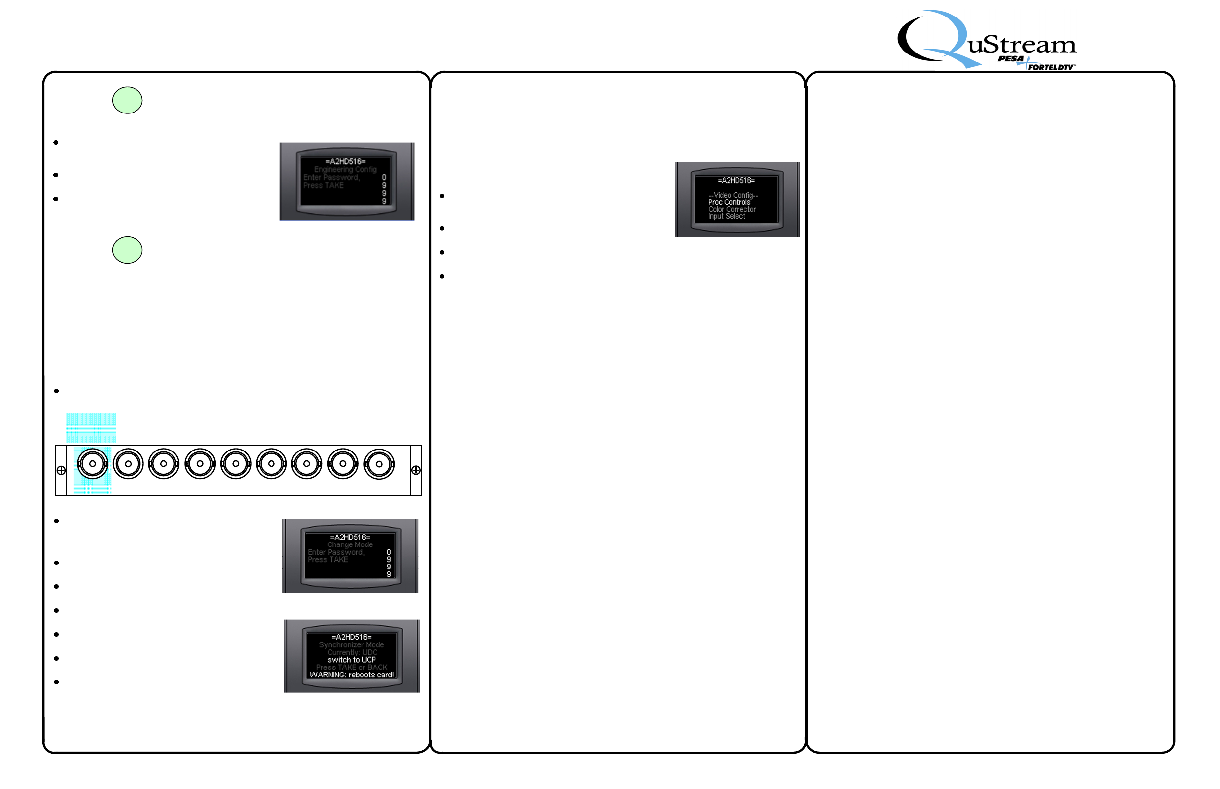
Certain menus are password protected. When a
protected menu is accessed, password entry
screen is displayed, as shown at right.
Use rotary knobs to set four highlighted digits to
0999, as shown.
Press TAKE to enter password and access
desired configuration menu screen.
Step
Your A2HD516 Processor is shipped from the factory with the UDC operating mode selected.
This mode allows the processor to function as an analog or SD-SDI to HD converter
WITHOUT using the included side column keyer function.
To use the side column keyer, you MUST provide an HD keyer input video signal and change
the processor to the UCP operating mode.
If UCP is selected as the operating mode and an HD signal is not applied to
the key video input connector, the A2HD516 WILL NOT function properly!!
C
ONFIGURING
Connect the keyer video source to the Input (IN) 1 BNC on the rear panel of the format
converter module as shown below. This video source must be an HD signal.
SIDE
COLUMN
KEYER
VIDEO INP UT
IN 1 OUT 1A OUT 1B OUT 2A OUT 2B OPTION BOPTION A GENLOCKIN 2
Access the Change Mode function from the
Video Configuration menu as directed in the
A2HD516 Video Configuration command listing
of the Menu Tree Reference portion of this guide.
Access to the Change Mode function is password
protected, as shown at right.
Use rotary knobs to set four highlighted digits to
0999, as shown.
Press TAKE to enter password and access
Change Mode menu screen.
Rotate the Select (Sel) control (A1) until the
“Switch to UCP” option is displayed, as shown.
Press TAKE to reboot the processor and change
operating mode of processor.
If you wish to return to UDC mode, access
Change Mode and select the “Switch to UDC”
option and press TAKE to change operating
mode.
7
8
A2HD516
K
BASIC OPERATION (CONT.)
USING SIDE COLUMN KEYER
(IF D
ESIRED
NOTE
FOR SIDE COLUMN KEYING
EYER VIDEO INPUT(FORMAT CONVERTER MODULE
)
)
M
ENU TREE
T
HIS P ORTION OF THE
BY LEVEL, OF ALL MAIN AND SUB MENUS AN D THE ASSOCIA TED COMMAND S FOR VIDEO
AND AUD IO CO NFIGURA TION FUNCTION S OF THE PROCES SOR
A2HD516 V
V
IDEO CONFIGURATION MENU SCREEN
Video configuration menus and sub-menus are
accessed through the Video Config screen, as
shown to right.
Use SEL knob to highlight desired menu entry, as
shown.
Press MENU to select desired configuration menu
screen.
Follow menu tree screen and command listings
below
IDEO CONFIGURATION
R
EFERENCE
A2HD516 Q
UICK START GUIDE PROVIDES A LISTING, INDE NTED
.
Video
{Video Config}
Proc Controls (A1 – Hue, A2 – Gain, A3 – Black, A4 – Chroma)
Hue (A1 to adjust setting)
Gain (A2 to adjust setting)
Black (A3 to adjust setting)
Chroma (A4 to adjust setting)
Color Corrector
White Balance
Red (A2 to change value)
Green (A3 to change value)
Blue (A4 to change value)
Black Balance
Red (A2 to change value)
Green (A3 to change value)
Blue (A4 to change value)
Gamma Balance
Red (A2 to change value)
Green (A3 to change value)
Blue (A4 to change value)
Black
Blk Stretch (A2 to change value)
Blk Lvl (A3 to change value)
CC Memory Save
Mem Bank (A2 to select desired memory location)
Press TAKE to save settings to memory location
CC Memory Recall
Mem Bank (A2 to select desired memory location)
Press TAKE to recall settings from memory location
Input Select
Input Sel
Input 1,2 (A1 to select desired setting)
OnVidLoss
Off, Black (A2 to select desired setting)
Anlg-SD Select
SDI, Analog-A, Analog-B (A1 to select desired setting)
Output
{Output Config}
Primary Output
Format
A1 to select desired video format from listing
Freeze Frame
Frame, Field 1, Field 2 (A2 to select desired setting)
TAKE to set Aspect Ratios
UC-AspRatio
A1 to change value
DC-AspRatio
A1 to select desired setting
DC-AR TrimH
A1 to change value
DC-AR TrimV
A1 to change value
Sec Asp Ratio
4X3-Crop, 4X3-Squeeze, 16X9-Lbox
A1 to select desired setting
HD Config
{HD Config}
HD CloCap
Off, On (A1 to select desired setting)
HD TimeCode
Off, On (A1 to select desired setting)
{HD Timing}
HD H Phase
A1 to change value
HD V Phase
A1 to change value
HD H Video Pos
A1 to change value
HD V Video Pos
A1 to change value
SD Config
{SD Config}
SD CloCap
Off, On (A1 to select desired setting)
Translate Timecode
Off, On (A1 to select desired setting)
SD Legalizer
Luma Limit
Off, Loose, Nominal, Tight
A1 to select desired setting
Encoded Limit
Off, Loose, Nominal, Tight
A1 to select desired setting
RGB Limit
Off, Loose, Nominal, Tight
A1 to select desired setting
VBI Legalizer
Is Off, Follows Main
A1 to select desired setting
M
ENU TREE CONTINUED ON NEXT PAGE
Part No. 81-9059-0647-0 Rev. B
Page 4
I
NTEGRITY
CS S
A2HD516 P
ERIES
ROCESSOR
Quick-Start Guide
M
ENU TREE
{SD Timing}
SD H Phase
SD V Phase
SD H Pos
SD V Pos
Genlock Source
Frame Connector, Board Connector
A1 to select desired source
Frame Rate
A1 to select desired frame rate setting
Test Pattern
A1 to select desired test pattern output from listing
Encoder Mode
On, Test Bars, Off (A1 to select desired setting)
Noise Reduction
Recursive Filter
Off, Auto, High, Low (A1 to change value)
Measured SNR (display)
Hot Switch
A1 to select desired Hot Switch action from listing
Status and Alarms
OvrTempThr
Over Temperature Alarm Threshold (A1 to change value)
Error Secs
Press TAKE to reset error seconds display
User Reset
Press TAKE to initiate User Reset
Change Mode
Password Prompt Screen
Use A1, A2, A3, A4 to select “0999”
Press TAKE to proceed to Change Mode screen
Change Mode
UDC, UCP (A1 to select desired setting)
Press TAKE to toggle mode selection
Info
Module 1 Info
Displays operational parameters for selected module
Frame Info
Displays operational parameters for chassis frame
R
EFERENCE
A1 to change value
A1 to change value
A1 to change value
A1 to change value
(C
ONT
.)
Eng Config
Password Prompt Screen
Use A1, A2, A3, A4 to select “0999”
Press TAKE to proceed to Eng Config screens
{Engineering Cnfgs}
Frame Config
{Module1 Cnfgs}
Vid Processing
{Module2 Vid Cnfgs}
Test Patterns
Dynamic Filters
Video-In Proc
Set Frame IP
A1 moves cursor left and right to select digit to change
A2 to change value of highlighted digit
Reboot Frame
Password Prompt Screen
Use A1, A2, A3, A4 to select “0999”
Press TAKE to initiate frame reboot
Status
Status display of frame operating parameters
Press TAKE to refresh
Full YUV Gamut
ON, Off (A1 to select desired setting)
Press TAKE to advance to next menu
NoiseReduce
On, Off (A1 to select desired setting)
NR Level
A1 to change value
Detail Enh
A1 to change value
Test Pattern (A1 to select desired test pattern from listing)
En/Dis (Press TAKE to enable/disable dynamic filter)
Coring (A1 to change value)
Luma Filter
Wide, Soft, Shaped, Dynamic (A2 to select desired setting)
Chr Filt
Flat, Shaped Dynamic, Flat Dynamic (A3 to select desired
setting)
Averaging
Off, Forced, High, Medium, Low (A4 to select desired setting)
Hue (A1 to adjust setting)
Gain (A2 to adjust setting)
Black (A3 to adjust setting)
Chroma (A4 to adjust setting)
{Analog In Config}
Comb Mode
Off, Line Adaptive, Frame Adaptive, Normal
A1 to select desired setting
Comb Sensitivity
Frame In-Ph (A1 to change value)
Frame Out-Ph (A2 to change value)
Line In-Ph (A3 to change value)
Line Out-Ph (A4 to change value)
Video TBC
Off, On, Auto (A1 to select desired setting)
Video AGC
Off, On (A1 to select desired setting)
{Additional Config}
Video Standard
Displays current operating video standard: NTSC/525 or PAL/625
Press TAKE to toggle between NTSC and PAL standards
Video Timing
Genlock
Genlock Status
Genlock Source Status Display (OK)
Genlock Source
Frame Connector, Board Connector
A1 to select desired source
Genlock Timing
V Phase (A1 to change value)
H Phase (A2 to change value)
Video Pos
H Video Pos
A1 to set desired position
V Video Pos
A1 to set desired position
Freeze Mode
Frame, Field 1, Field 2 (A1 to select desired setting)
Configure VBI
Config Line/Field
10/1, 10/2….22/1, 22/2 (A1 to select desired setting)
Signal
A2 to select desired signal type from listing
Setup
0.0, 7.5 IRE (A3 to select desired setting)
Comb
Off, On (A4 to select desired setting)
User Reset
Press TAKE to initiate User Reset
M
ENU TREE CONTINUED ON NEXT PAGE
Part No. 81-9059-0647-0 Rev. B
Page 5
I
NTEGRITY
CS S
A2HD516 P
ERIES
ROCESSOR
Quick-Start Guide
M
ENU TREE
A2HD516 A
A
UDIO CONFIGURATION MENU SCREEN
Audio configuration menus and sub-menus are
accessed through the Audio Config screen, as
shown to right.
Use SEL knob to highlight desired menu entry, as
shown.
Press MENU to select desired configuration menu
screen.
Follow menu tree screen and command listings
below
UDIO CONFIGURATION
R
EFERENCE
Audio
{Audio Config}
Audio Config (Demb)
Output Sources
Chan (A1 to select channel 1 to 16)
IsSource (A2 to select source from listing)
SumWith (A3 to select source from listing)
SumBalance (A4 to change value)
Chan Lvl-Mute-Ph
Audio Out Level
A1 to select group containing channel to adjust
(Using Chan 1...4 entry for reference)
Ch 1 (A1 to change value)
Ch 2 (A2 to change value)
Ch 3 (A3 to change value)
Ch 4 (A4 to change value)
Audio Out Mute (Same steps as Audio Out Level, above)
Audio Out Phase (Same steps as Audio Out Level, above)
Bank Lvl-ALC-Lim
Bank Level
Bank 1 (A1 to change value)
Bank 2 (A2 to change value)
Bank 3 (A3 to change value)
Bank 4 (A4 to change value)
ALC
Bank Select 1-4(A1 to select bank)
ALC Enable
Off, On (A2 to select desired setting)
ALC Level (A3 to change value)
ALC Rate (A4 to change value)
Limiter
Bank Select 1-4(A1 to select bank)
Lim Enable
Off, On (A2 to select desired setting)
Lim Level (A3 to change value)
Lim Rate (A4 to change value)
Bank Config
(A1 to assign groups to bank 1)
(A2 to assign groups to bank 2)
(A3 to assign groups to bank 3)
(A4 to assign groups to bank 4)
(C
ONT
.)
Lip-Sync
Tracking
Slow, Medium, Fast (A1 to select desired setting)
Add Offset (A2 to change value)
Tone Gen Freq
Tone Gen 1 (A1 to select desired operating frequency)
Tone Gen 2 (A2 to select desired operating frequency)
Tone Gen 3 (A3 to select desired operating frequency)
Tone Gen 4 (A4 to select desired operating frequency)
Tone Gen Level
Tone Gen 1 (A1 to change value)
Tone Gen 2 (A2 to change value)
Tone Gen 3 (A3 to change value)
Tone Gen 4 (A4 to change value)
Embed Enable
On, Off (A1 to select desired setting)
{Adj Audio Board}
DeEmbed to DAS
None, Grp 1, Grp 2, Grp 3, Grp 4 (A1 to select desired setting)
Embed DAS Audio
None, Grp 1, Grp 2, Grp 3, Grp 4 (A1 to select desired setting)
Audio Config (Ext 1)
Output Sources
Chan (A1 to select channel 1 to 16)
IsSource (A2 to select source from listing)
SumWith (A3 to select source from listing)
SumBalance (A4 to change value)
AES Sources
AES-1.1 (A1 to select source from listing)
AES-1.2 (A2 to select source from listing)
AES-2.1 (A3 to select source from listing)
AES-2.2 (A4 to select source from listing)
Chan Lvl-Mute-Ph
Audio Out Level (A1 to select group containing channel to adjust)
(Using Chan 1...4 entry for reference)
Audio Out Mute (Same steps as Audio Out Level, above)
Audio Out Phase (Same steps as Audio Out Level, above)
Ch 1 (A1 to change value)
Ch 2 (A2 to change value)
Ch 3 (A3 to change value)
Ch 4 (A4 to change value)
Bank Lvl-ALC-Lim
Bank Level
Bank 1 (A1 to change value)
Bank 2 (A2 to change value)
Bank 3 (A3 to change value)
Bank 4 (A4 to change value)
ALC
Bank Select 1-4(A1 to select bank)
ALC Enable
Off, On (A2 to select desired setting)
ALC Level (A3 to change value)
ALC Rate (A4 to change value)
Limiter
Bank Select 1-4(A1 to select bank)
Lim Enable
Off, On (A2 to select desired setting)
Lim Level (A3 to change value)
Lim Rate (A4 to change value)
Bank Config
(A1 to assign groups to bank 1)
(A2 to assign groups to bank 2)
(A3 to assign groups to bank 3)
(A4 to assign groups to bank 4)
Lip-Sync
Tracking
Slow, Medium, Fast (A1 to select desired setting)
Add Offset (A2 to change value)
Analog In Gain Trim
Analog In 1 (A1 to change value)
Analog In 2 (A2 to change value)
Analog In 3 (A3 to change value)
Analog In 4 (A4 to change value)
Tone Gen Freq
Tone Gen 1 (A1 to select desired operating frequency)
Tone Gen 2 (A2 to select desired operating frequency)
Tone Gen 3 (A3 to select desired operating frequency)
Tone Gen 4 (A4 to select desired operating frequency)
Tone Gen Level
Tone Gen 1 (A1 to change value)
Tone Gen 2 (A2 to change value)
Tone Gen 3 (A3 to change value)
Tone Gen 4 (A4 to change value)
Embed Enable
On, Off (A1 to select desired setting)
M
ENU TREE CONTINUED ON NEXT PAGE
Part No. 81-9059-0647-0 Rev. B
Page 6
I
NTEGRITY
A2HD516 P
M
ENU TREE
Audio Config (Ext 2)
{Input Control}
Input Gain A1 A2
Linking
Mono, Stereo (A1 to select desired setting)
Gain A1 (Mono), Gain (Stereo), A2 to change value
Gain A2 (Mono), Balance (Stereo), A3 to change value
Input Gain A3 A4
Linking
Mono, Stereo (A1 to select desired setting)
Gain A3 (Mono), Gain (Stereo), A2 to change value
Gain A4 (Mono), Balance (Stereo), A3 to change value
Input Gain D1 D2
Linking
Mono, Stereo (A1 to select desired setting)
Gain D1 (Mono), Gain (Stereo), A2 to change value
Gain D2 (Mono), Balance (Stereo), A3 to change value
Input Gain D3 D4
Linking
Mono, Stereo (A1 to select desired setting)
Gain D3 (Mono), Gain (Stereo), A2 to change value
Gain D4 (Mono), Balance (Stereo), A3 to change value
Phase/Mute/Bypass
CHANNEL
A1, A2, A3, A4, D1, D2, D1-D2, D3, D4, D3-D4
A1 to select desired setting
Phase
Normal, Invert (A2 to select desired setting)
Mute
Off, On (A3 to select desired setting)
Bypass
Off, On (A4 to select desired setting)
{Routing Config}
Routing Presets
Cfg-A, Cfg-B, Follow-VideoIn (A1 to select desired setting)
Dig Source
Group 1, Group 2, Group 3, Group 4, BNC
A1 to select desired setting)
Source
Output Chan
A1, A2, A3, A4, D1, D2, D3, D4
A1 to select desired setting
Source
A1, A2, A3, A4, D1, D2, D3, D4, Tone
A2 to select desired setting
Sum With
A1, A2, A3, A4, D1, D2, D3, D4, Tone
A3 to select desired setting
CS S
ROCESSOR
R
EFERENCE
ERIES
(C
ONT
.)
Quick-Start Guide
{Configuration}
Delay Setup
CHANNEL
All, A1, A2, A3, A4, D1, D2, D3, D4 (A1 to select desired setting)
Tracking
Internal, None, Ext TTL1, Ext TTL2 (A2 to select desired setting)
Slew Rate
Slow, Medium, Fast (A3 to select desired setting)
Offset (A4 to change value)
Embedding
Embed to Group
Group1, 2, 3, 4, None (A1 to select desired setting)
Headroom
Analog 1 (A1 to change value)
Analog 2 (A2 to change value)
Analog 3 (A3 to change value)
Analog 4 (A4 to change value)
Test Tone Config
CHANNEL
A1, A2, A3, A4, D1, D2, D3, D4 (A1 to select desired channel)
Frequency (A2 to change value)
Level (A3 to change value)
AES Config
Output Sample Rate
32, 44.1, 48, 96 kHz (A1 to select desired setting)
Output Word Length
16, 20, 24 bits (A1 to select desired setting)
Output Sample Ref
AES Blk, Video (A1 to desired setting)
IN THE EVENT OF TROUBLE
If you have any problems with or questions about your QuStream A2HD516 video
processor, contact QuStream Customer Service by phone or e-mail.
Customer Service: 1+ (256) 726-9222
Toll Free: (800) 323-7372 (US and Canada)
Fax: 1+ (256) 726-9268
Email: [email protected]
Part No. 81-9059-0647-0 Rev. B
 Loading...