

Page 1

Cougar Digital Video
PESA Switching Systems
330A Wynn Drive
Huntsville, AL 35805
Document No. 81-9059-0344-0 Rev. B
Page 2

Manual Updates:
10/15/95 Manual released for initial printing.
04/30/96 Updated manual to incorporate ECO changes.
04/20/98 Updated manual to incorporate ECO changes.
03-02-01 Rev B: Deleted Printing Specification per ECO CE00113. GLT
Page 3
Ordering Assistance,
Service & Inquiries
Service and
Ordering
Assistance
Sales Office
PESA Switching Systems, Inc.
330A Wynn Drive
Huntsville, AL 35805
Main Numbers:
Tel: (256) 726-9200
Fax: (256) 726-9271
Service Department Numbers:
Tel: (256) 726-9222
Fax: (256) 726-9268
National Sales Office
PESA Switching Systems, Inc.
35 Pinelawn Road, Suite 99E
Melville, NY 11747
Tel: (800) 328-1008
Fax: (516) 845-5023
Page 4
NOTE
PESA reserves the right to change any information con-
tained in this manual without notice. Unauthorized copying,
modifications, distribution, or display is prohibited. All rights
reserved.
Please address all comments or suggestions concerning
this or other PESA manuals to:
Publications Department
Attn: Charles E. Jaynes
(Engineering Technical Writer)
PESA Switching Systems, Inc.
330A Wynn Drive
Huntsville, Alabama 35805
(256) 726-9200 EXT. 145
Page 5
ATTENTION
ALL EQUIPMENT ITEMS
MANUFACTURED BY OR SOLD BY
PESA SWITCHING SYSTEMS, INC.
ATTENTION
SHOULD BE SERVICED BY
QUALIFIED SERVICE PERSONNEL
OR BY QUALIFIED SERVICE
TECHNICANS ONLY.
Page 6

Table of Contents
Cougar Digital Video
Section 1. Introduction
1.1 Manual Overview ...................................................................... 1.1
1.2 General Description .................................................................. 1.2
1.3 Specifications ............................................................................ 1.4
Figure 1-1 Cougar Digital Video Routing Switcher Front and Rear ..... 1.3
Section 2. Installation
2.1 Introduction...............................................................................2.1
General............................................................................... 2.1
2.2 Receipt Inspection .................................................................... 2.1
2.3 Unpacking................................................................................. 2.2
2.4 Location .................................................................................... 2.2
2.5 Mounting ................................................................................... 2.2
2.6 Cabling...................................................................................... 2.3
2.7 Level Code (Strobe) Selection................................................. 2.4
2.8 Output/Input Code Selection..................................................... 2.5
Output Code ....................................................................... 2.6
Input Code .......................................................................... 2.7
2.9 System Controller Card Installation .......................................... 2.8
2.10 PS70V Setting Line Voltage ..................................................... 2.9
2.11 PS70V Power Supply Installation ............................................. 2.9
2.12 32X32 Digital Video Matrix Card Installation............................. 2.10
2.13 Rear Panel Connectors ............................................................ 2.11
RCP Panel Connectors (J9-J12) ........................................ 2.11
Serial (CPU Link) Connectors (J13 and J14)..................... 2.11
Control (PRC) Connectors (J15 and J93)........................... 2.12
CPU Alarm Connector (J16) ............................................... 2.12
Matrix Card Alarm Connector (J17) .................................... 2.13
Power In/Out Connector (J18) ............................................ 2.13
Power Supply Alarm Connectors (J23 and J24)................. 2.13
Reference (Sync) Connectors (1 and 2) ............................ 2.13
Video Input and Output Connectors ................................... 2.14
2.14 System Connections................................................................. 2.14
Connection Guide............................................................... 2.14
Figures
4/98
P/N 81905903440
i
Page 7

Table of Contents
Cougar Digital Video
Section 2. Installation Continued:
Figure 2-1 Chassis Installation ............................................................ 2.3
Figure 2-2 Cables Attached to Supports ............................................. 2.4
Figure 2-3 Level Code Selection ......................................................... 2.4
Figure 2-4 Coding Switch Locations.................................................... 2.5
Figure 2-5 Output Code Selection ....................................................... 2.6
Figure 2-6 Input Code Selection.......................................................... 2.7
Figure 2-7 Cougar Digital Video Routing Switcher Rear View............. 2.11
Section 3. Operation
Figures
3.1 Operation of the Cougar Digital Video Routing Swit................. 3.1
General............................................................................... 3.1
3.2 Regulator Fault LED (Red) ....................................................... 3.1
3.3 CPU Fault LED (Red) ............................................................... 3.1
3.4 Power OK LED (Green) ............................................................ 3.1
3.5 32X32 Digital Video Matrix Card Adjustments .......................... 3.1
Section 4. Functional
4.1 Introduction............................................................................... 4.1
General............................................................................... 4.1
4.2 32X32 Digital Video Matrix Card............................................... 4.1
Control ................................................................................ 4.1
Crosspoint Matrix................................................................ 4.1
Input Equalizers .................................................................. 4.2
Output Drivers..................................................................... 4.2
Power Regulators ............................................................... 4.2
4.3 PS70V Power Supply ............................................................... 4.2
Circuit Description............................................................... 4.3
4/98
ii
P/N 81905903440
Page 8

Table of Contents
Cougar Digital Video
Section 5. Maintenance
5.1 Introduction............................................................................... 5.1
5.2 General..................................................................................... 5.1
5.3 Test Equipment ......................................................................... 5.1
5.4 Preventive Maintenance ........................................................... 5.2
5.5 Maintenance ............................................................................. 5.2
5.6 Corrective Maintenance............................................................ 5.2
Factory Repair Service ....................................................... 5.2
Troubleshooting.................................................................. 5.3
System Checks................................................................... 5.4
Replacement Parts ............................................................. 5.4
5.7 Filter Cleaning........................................................................... 5.4
5.8 PS70V Power Supply ............................................................... 5.5
Section 6. Schematics
6.1 Schematics ............................................................................... 6.1
General............................................................................... 6.1
Cougar Mainframe ....................................CD63-0758 ............ 6.2
Cougar Chassis ........................................CD63-0759 ............ 6.3
32X32 Video Backplane ...........................CA25-1281 ............ 6.4
............................................................SC33-1281 ............ 6.6
32X32 Digital Video Matrix Card...............CA25-1278 ............ 6.8
............................................................SC33-1278 ............ 6.10
Power Supply Assembly ........................... CD63-0683 ............ 6.19
Power Supply Card................................... CA25-1162 ............ 6.20
............................................................SC33-1162 ............ 6.21
Section 7. Parts List
7.1 Parts List................................................................................... 7.1
General............................................................................... 7.1
Cougar Mainframe ....................................81906517410......... 7.2
Cougar Chassis ........................................81906517510......... 7.3
32X32 Video Backplane ...........................81906517520......... 7.4
32X32 Digital Video Matrix Card...............81906517480......... 7.5
Power Supply Assembly ........................... 81906514550......... 7.9
Power Supply Card................................... 81906514540......... 7.10
4/98
P/N 81905903440
iii
Page 9
Digital Video
1.1 Manual Overview
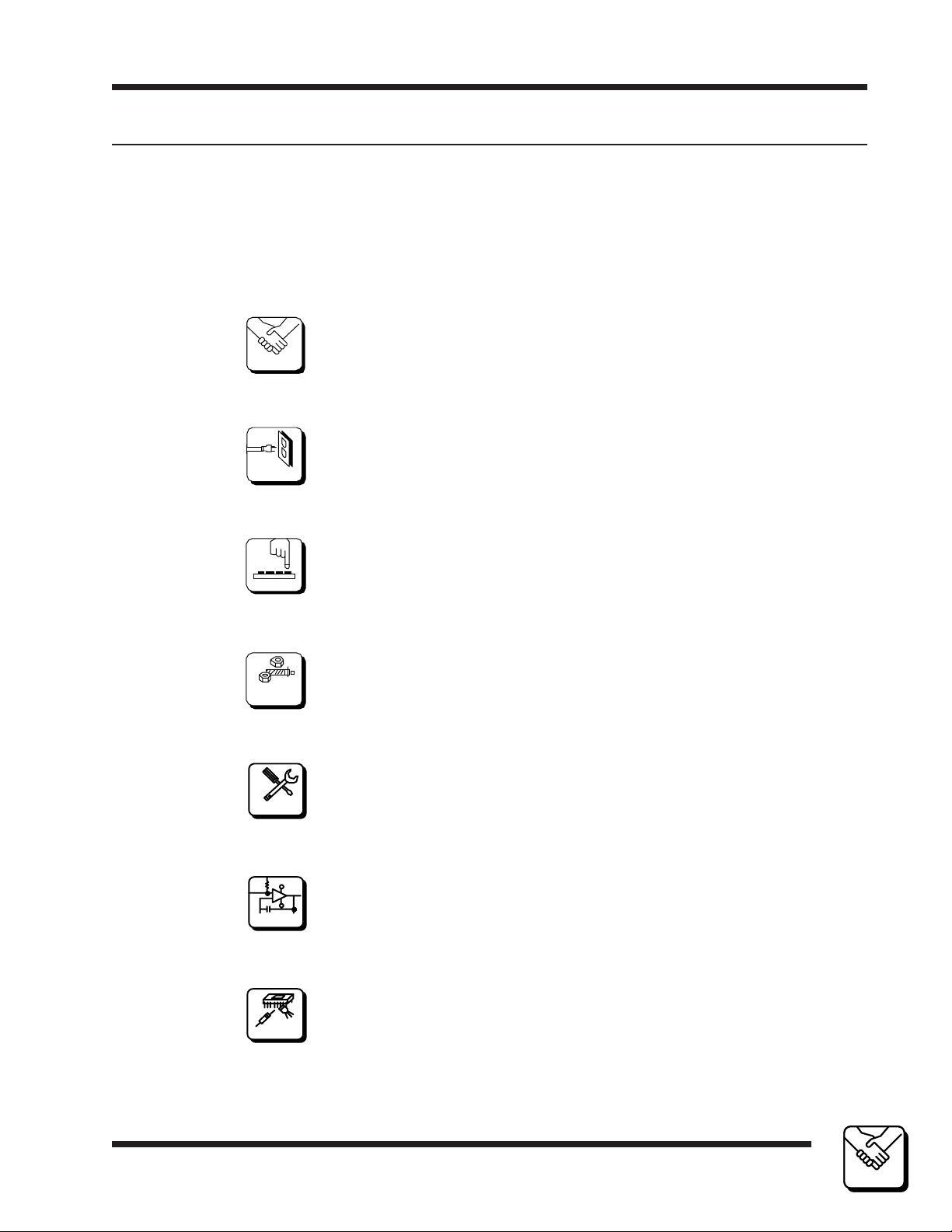
This manual provides detailed instructions for installing and operating the PESA
Cougar Digital Video Switcher. This manual is divided into seven sections as
shown. Sections 3 and 4 contain operational and functional descriptions of the
Cougar Digital Video Routing Switcher and the associated 32X32 Digital Video
Matrix Card.
Introduction Section 1
1
1
INTRODUCTIO N
INTRODUCTIO N
2
INSTA LLATION
3
OPERATI ON
4
FU NCTIO NAL
DESCRIPTION
5
MAINTENANCE
Section 1, INTRODUCTION, summarizes the manual, describes
the product, presents a list of terms, and provides the panel
specifications.
Section 2, INSTALLATION, provides installation and setup
instructions.
Section 3, OPERATION, describes system operation procedures.
Section 4, FUNCTIONAL DESCRIPTIONS, presents an indepth description of each component.
Section 5, MAINTENANCE, explains procedures for mainte-
nance.
6
SCHEM ATICS
7
PARTS LISTS
Section 6, SCHEMATICS, gives a complete package of technical documents such as schematics, and assembly drawings.
Section 7, PARTS LIST, provides a detailed list of system parts
and components.
4/98
P/N 81905903440 page 1.1
1
1
INTRODUCTION
INTRODUCTION
Page 10

Digital Video
Introduction Section 1
1.2 General Description
The PESA Cougar Digital Video Routing Switcher offers a reliable low cost
answer to your digital video routing needs. The Cougar Digital Video Routing
Switcher is housed in a 3RU frame providing a small profile for space efficient
installations. The Cougar Frame can be equipped with either a single System
Controller or dual System Controllers. The option of dual controllers provides
seamless transfer of system control in case of equipment failure. The Cougar
Frame can also be equipped with redundant power supplies for maximum
reliability and fail safe operation.
The Cougar Digital Video Routing Switcher is designed with small to mid-range
size routing matrix applications in mind. This cost efficient router is expandable to
a 64X64 size matrix utilizing four Cougar Digital Video Routing Switchers and two
MVDA Combiners. The main matrix components use plug-in circuit cards for
ease of maintenance and component replacement. The Cougar Digital Video
Routing Switcher can be serviced hot, allowing circuit card changes without
powering down the matrix. Board level voltage regulation in the Cougar Frame
eliminates the possibility of a central, single point power failure.
The Cougar Digital Video Matrix Card features easily visible LED indicators for
quick view of critical voltage and circuit conditions. The Cougar Frame comes
equipped with one control port, two RS232 ports, four RS485 control panel ports,
and external alarm connectors for audible monitoring of the operation of the
internal power and controller circuits. Please note that the control port, the
RS232 port, and the four RS485 ports are only active when a controller card is
installed in the Cougar Frame. The Cougar Frame utilizes RS485 looping
interfaces for system connection to remote control panels using standard twisted
pair cables.
The Cougar Digital Video Routing Switcher utilizes the PESA System Controller
for system control. The System Controller provides a user friendly graphical
interface; operating in a Windows 3.1™ personal computer environment. The
System Controller can be installed internal to the Cougar Frame, allowing better
rack space utilization. The Cougar Digital Video Routing Switcher working in
conjunction with the System Controller utilizes PESA's low cost RCP line of
control panels for remote system operation.
The Cougar Digital Video Matrix Card is compatible with digital composite, digital
component, and compressed digital HDTV video formats. The Cougar Digital
Video Matrix card provides automatic input equalization for up to 240 meters of
Belden 8281 cable for data rates up to 270 Mbit/s, and up to 150 meters of cable
for data rates up to 360 Mbit/s.
1
1
INTRODUCTION
INTRODUCTION
page 1.2
4/98
P/N 81905903440
Page 11
Digital Video
Introduction Section 1
1.2 General Description Continued:
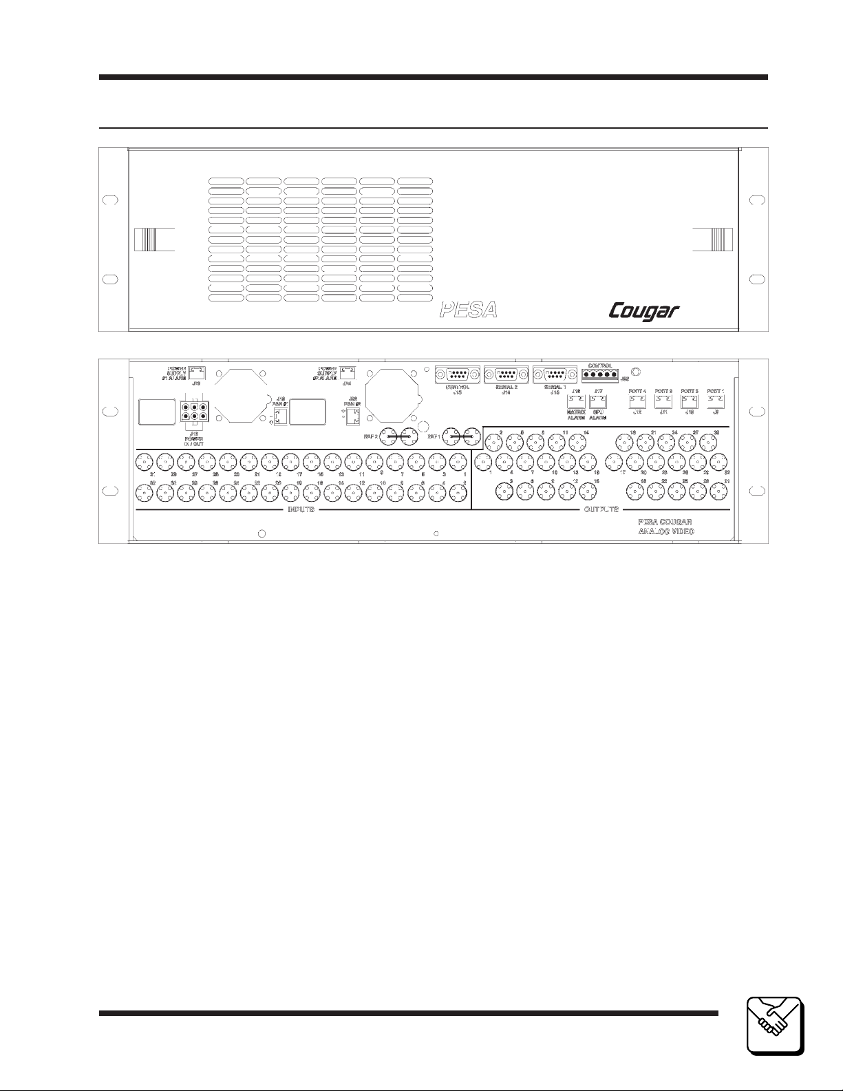
Figure 1-1 Cougar Digital Video Routing Switcher Front and Rear Views
4/98
P/N 81905903440 page 1.3
1
1
INTRODUCTION
INTRODUCTION
Page 12

Digital Video
Introduction Section 1
1.3 Specifications
INPUTS
Impedance 75 Ohm, Internally Terminated, Non-Looping, BNC
Return Loss >15dB 5MHz to 270MHz
Standard SMPTE 259M for (D1, 270Mbit/s),
(D2 or D3, NTSC, 143Mbit/s),
(D2 or D3, PAL, 177Mbit/s),
and the proposed (Compressed, 16:9 HDTV, 360Mbit/s)
Equalization Automatic equalization for 0 to 240 meters
of Belden 8281 or equivalent cable for
data rates up to 270Mbit/s and 0 to 150 meters
for data rates up to 360Mbit/s
Number 32
OUTPUTS
Impedance 75 Ohm BNC
Return Loss >15dB 5MHz to 270MHz
Signal Amplitude 800mv ±10%, Terminated into 75 Ohms
DC Offset ±0.5V, Terminated into 75 Ohms
Rise/Fall Times 0.6nS ±200pS (20% to 80%), Terminated into 75 Ohms
Timing Jitter 0.2UI p-p as defined in SMPTE 259M
Alignment Jitter 0.2UI p-p as defined in SMPTE 259M
Standard SMPTE 259M for (D1, 270Mbit/s),
(D2 or D3, NTSC, 143Mbit/s),
(D2 or D3, PAL, 177Mbit/s),
and the proposed (Compressed, 16:9 HDTV, 360Mbit/s)
Number 32
1
1
INTRODUCTION
INTRODUCTION
page 1.4
4/98
P/N 81905903440
Page 13

Digital Video
2.1 Introduction
This section details the Cougar Digital Video Routing Switcher installation
procedures. The following topics are discussed:
• Receipt Inspection
• Unpacking
• Location
• Mounting
• Cabling
• Level Code (Strobe) Selection
• Input/Output Coding Selection
• System Controller Card Installation
• PS70V Setting Line Voltage
• PS70V Power Supply Installation
• 32X32 Digital Video Matrix Card Installation
• Rear Panel Connectors
• System Connections
Installation
Section 2
General
If specified when ordered, the Cougar Digital Video Frame will be configured for the intended system at the factory. Before attempting to install
any frame, matrix card, controller card, or power supply; this section
should be read carefully.
NOTICE
THE COUGAR DIGITAL VIDEO ROUTING SWITCHER CONTAINS STATIC SENSITIVE
DEVICES. CARE SHOULD BE USED WHEN IT IS NECESSARY TO HANDLE THE
INTERNAL CIRCUIT CARDS. IT IS RECOMMENDED THAT A GROUND WRIST STRAP
AND GROUNDING MAT BE USED BEFORE ATTEMPTING ANY EQUIPMENT INSTALLATIONS.
2.2 Receipt Inspection
The Cougar Digital Video Routing Switcher was tested and inspected
prior to leaving the factory. Upon receipt, inspect the equipment for shipping damage. If any damage is found, contact the carrier immediately and
save all packing material.
10/95
P/N 81905903440
page 2.1
2
INSTALLATION
Page 14

Digital Video
2.3 Unpacking
The Cougar Digital Video Matrix Switcher is comprised of a frame, backplane, a 32X32 Digital Video Matrix Card, up to two System Controller
Cards, and up to two PS70V Power Supplies. Prior to discarding packing
material compare the parts received against the packing list. Carefully
inspect the layers of packing material for any components which may
have been overlooked during the initial unpacking.
2.4 Location
The Cougar Digital Video Routing Switcher may be located anywhere
power is available. However, units should be mounted as close as possible to their associated equipment to minimize cable runs. Forced air
cooling is provided by a small fans located at the back of the unit. Care
should be taken not to block airflow around these fans. Installation should
be in an area where the ambient temperature does not exceed 40°C
(104°F) inside the equipment rack.
Section 2Installation
2.5 Mounting
The Cougar Digital Video Routing Switcher is rack mountable in a standard 19” equipment rack. Sufficient space must be provided behind the
equipment racks to allow for the control cables and power cable. All
mounting holes should be utilized and mounting hardware tightened
securely. As with all equipment installed in a rack, the bottom screw on
each side should be installed before proceeding with the remainder of the
screws. Then all screws should be securely tightened. Support the Cougar
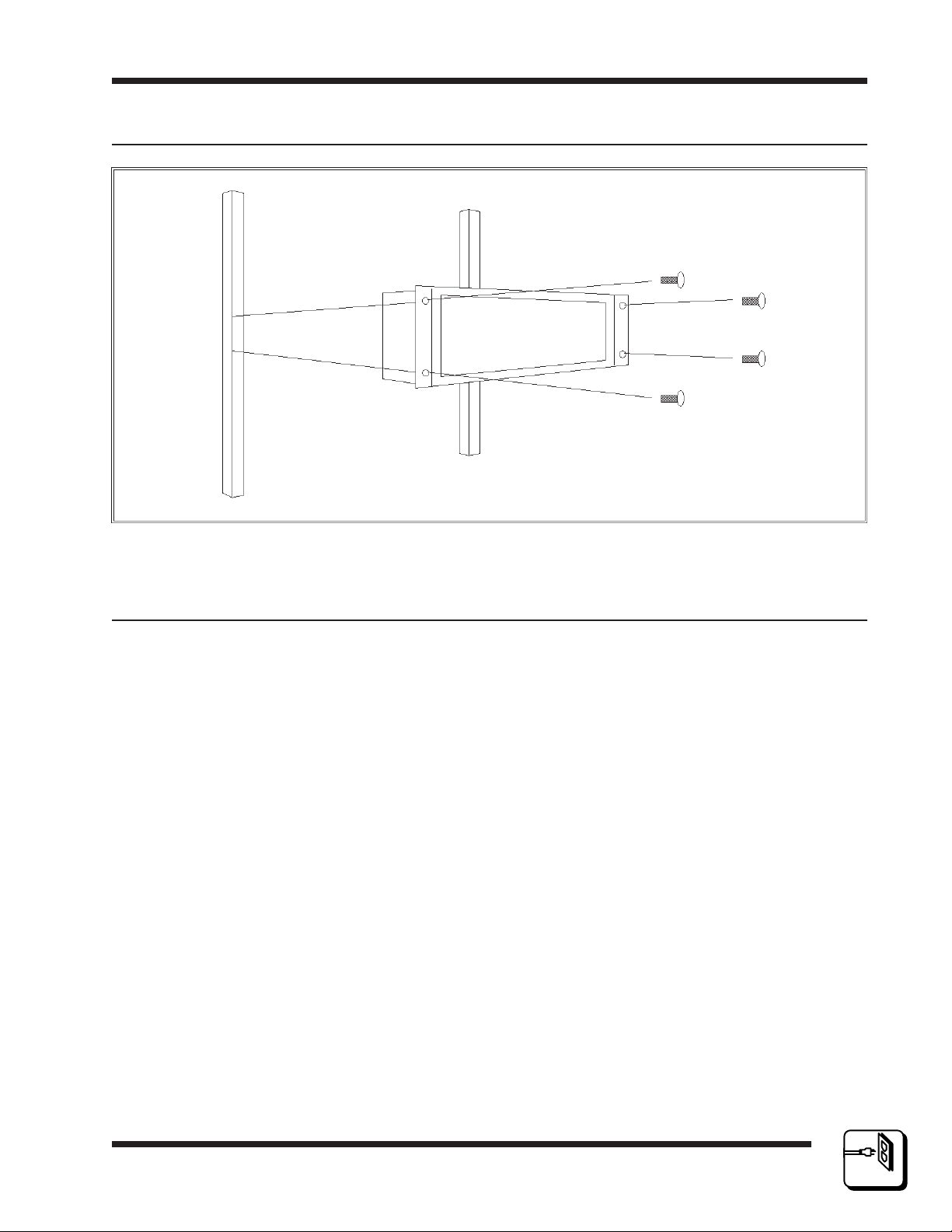
Digital Switcher's bottom while installing it in the rack. Figure 2-1 illustrates
chassis installation in the equipment rack. NOTE: Remove the power
supply retaining screws before installing the Cougar Digital Video Routing
Switcher in an equipment rack.
To install a Cougar Digital Video Routing Switcher in an equipment rack
follow these steps:
1. Align the frame with the slotted opening in the rack.
2. Install the bottom screws first.
2
INSTALLATION
page 2.2
3. Install the two top screws
4. Tighten all four screws securely.
10/95
P/N 81905903440
Page 15
Digital Video
Installation
2.5 Mounting Continued:
Section 2
2.6 Cabling
Considerable weight will be added to the rear panel of the Cougar Digital
Video Routing Switcher by the control, signal, and power cables. Therefore, all cables should be strained relieved and secured to racks or other
supporting structures. Failure to provide adequate cable support can result
in cables separating from connectors. If cable runs are to be stored under
an elevated floor, they should be tied to the racks as a guide. If cables are
run along the floor, do not allow them to lay in the work area behind the
racks. Stepping or tripping on the cables may result in connections being
pulled free or wire breakage inside the insulation. The Cougar Digital
Video Routing Switcher should be installed in the equipment rack prior to
attaching cables.
Use the following rules when cabling the Cougar Digital Video Routing
Switcher:
1. Lay all cables in their intended positions, separating control, video, and
Figure 2-1 Chassis Installation
power cables wherever possible.
10/95
P/N 81905903440
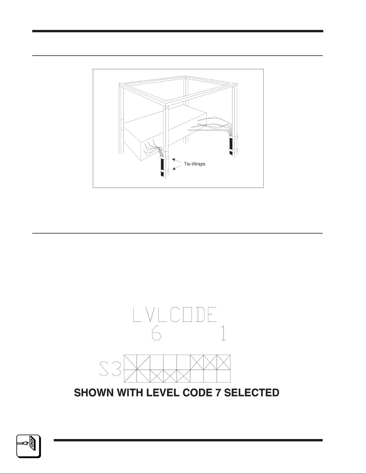
2. Provide proper support for each cable during the cabling process. The
use of tie-wraps is recommended as shown in Figure 2-2.
page 2.3
2
INSTALLATION
Page 16
Digital Video
2.6 Cabling Continued:
Figure 2-2 Cables Attached to Supports
Section 2Installation
2.7 Level Code (Strobe) Selection
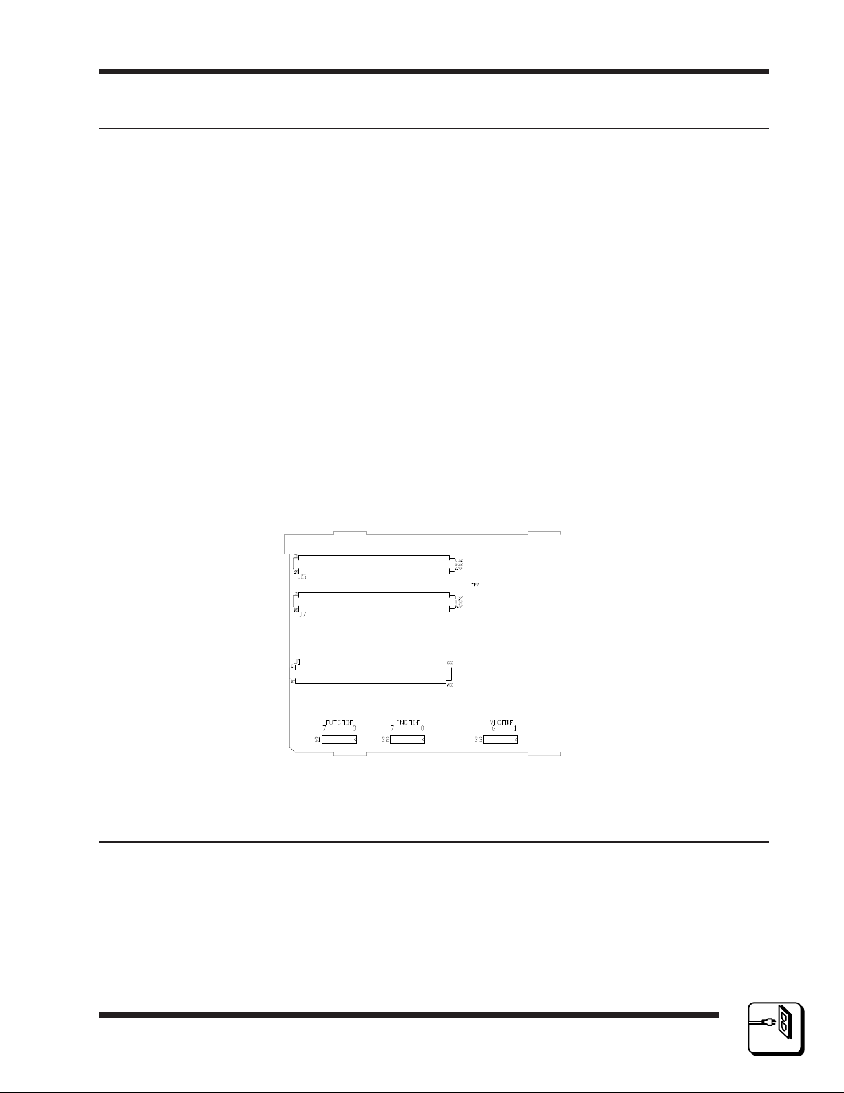
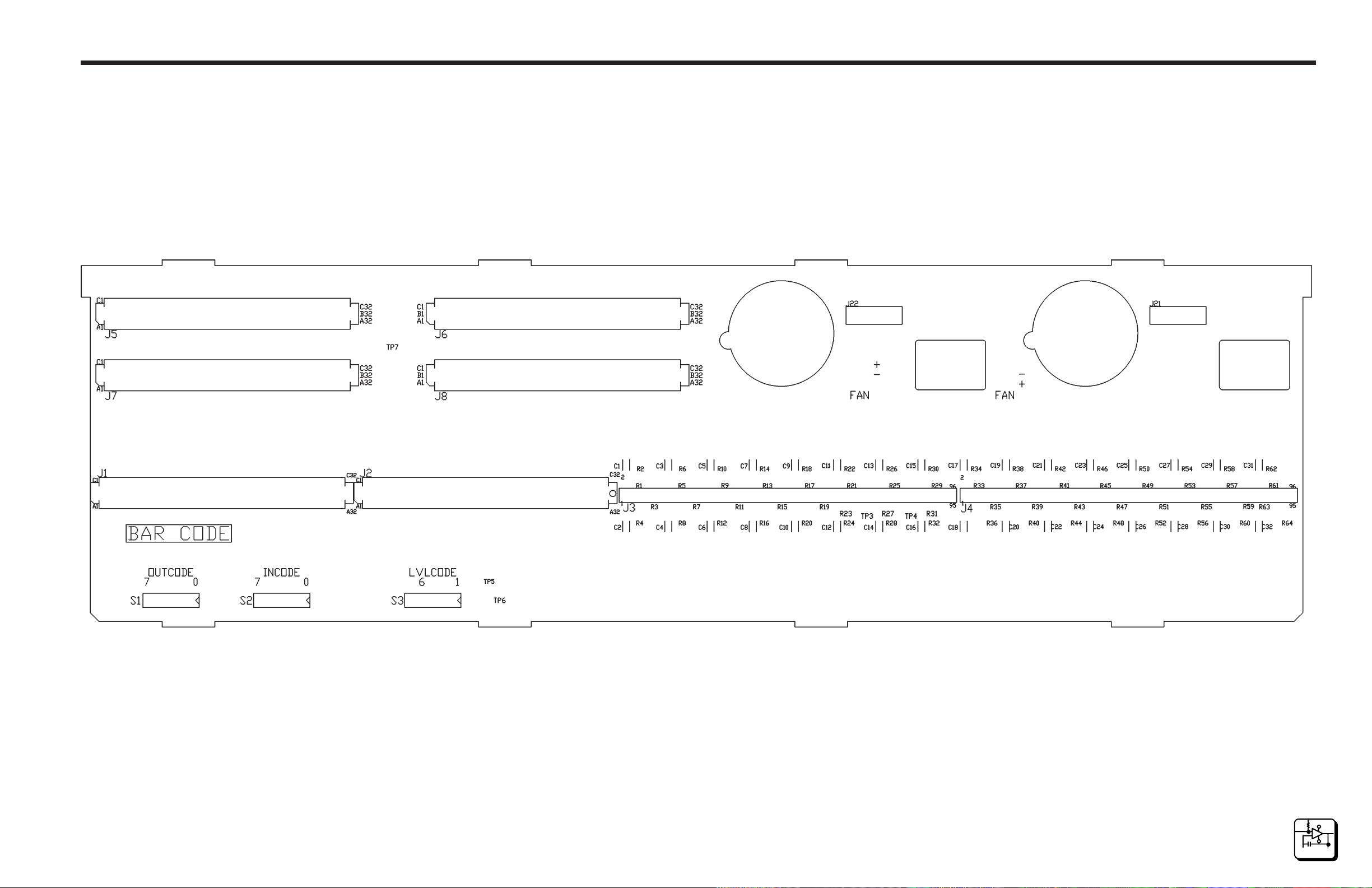
The level (strobe) select switch, S3, (a binary coded switch) is located on
the inside of the Cougar Digital Video Routing Switcher on lower left-hand
side of the backplane. Switch numbers are 1 through 8 right to left.
Switches 1-6 select level codes 0 through 62. Switches 7 and 8 are not
used – their position is unimportant. Refer to Figure 2-3 for an example
of level code selection and see Figure 2-4 for the physical location of the
level code switch.
2
INSTALLATION
page 2.4
Figure 2-3 Level Code Selection
10/95
P/N 81905903440
Page 17
Digital Video
Installation
2.7 Level Code (Strobe) Selection Continued:
Physical 0 (Logical 1) = OFF (UP)
Physical 1 (Logical 0) = ON (DOWN)
NOTE: The following are logical selections. Level 0 is all switches on
(down) or all switches in the physical 1 position.
SWITCH POSITIONS 654321
STROBE LEVEL 0 000000
STROBE LEVEL 1 000001
STROBE LEVEL 2 000010
STROBE LEVEL 3 000011
STROBE LEVEL 4 000100
STROBE LEVEL 5 000101
STROBE LEVEL 6 000110
STROBE LEVEL 7 000111
UP TO....
STROBE LEVEL 62 111110
Section 2
Figure 2-4 Coding Switch Locations
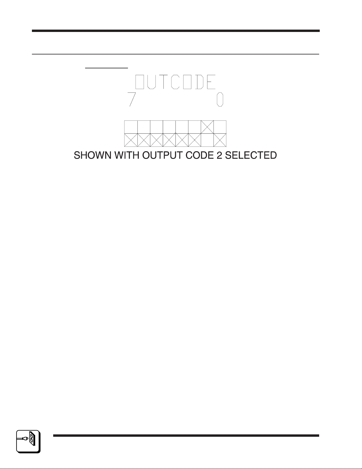
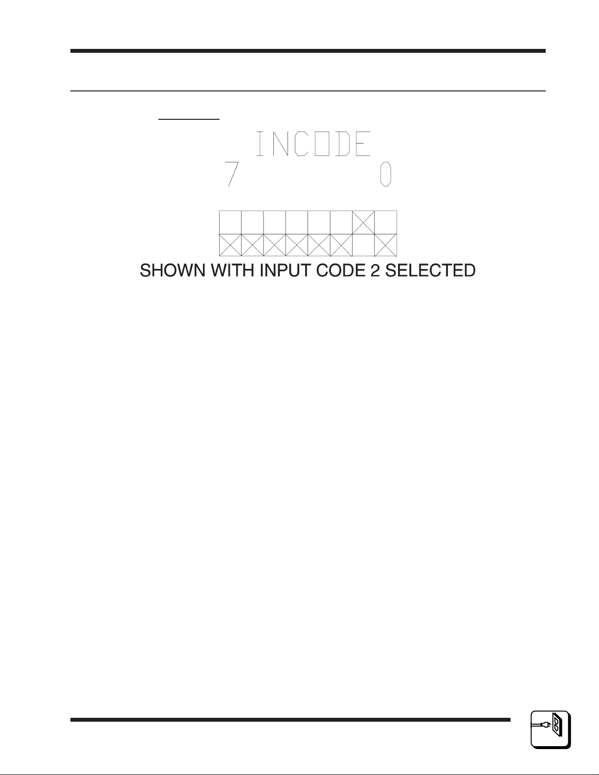
2.8 Output/Input Code Selection
Input and output coding switches are located on the inside of the Cougar
Digital Video Routing Switcher on the lower left corner of the backplane.
The input and output switch numbers run 0 to 7, right to left. Switch S1
(outcode switch) selects output codes 0-255 and switch S2 (incode switch)
selects input codes 0-255. Refer to Figures 2-5 and 2-6 for examples of
input and output code selection and see Figure 2-4 for the physical location of the output and input code switches.
10/95
P/N 81905903440
page 2.5
2
INSTALLATION
Page 18
Digital Video
2.8 Input/Output Code Selection Continued:
Output Code
Figure 2-5 Output Code Selection
Physical 0 (Logical 1) = OFF (UP)
Physical 1 (Logical 0) = ON (DOWN)
Section 2Installation
NOTE: The following are logical selections. Output code 0 is all switches
on (down) or all switches in the physical 1 position.
SWITCH POSITION 76543210OUTPUTS
OUTPUT CODE 0 000000000-32
OUTPUT CODE 1 0000000133-64
OUTPUT CODE 2 0000001065-96
OUTPUT CODE 3 0000001197-128
OUTPUT CODE 4 00000100129-160
OUTPUT CODE 5 00000101161-192
OUTPUT CODE 6 00000110193-224
OUTPUT CODE 7 00000111225-256
UP TO....
OUTPUT CODE 255111111118161-8192
2
INSTALLATION
page 2.6
10/95
P/N 81905903440
Page 19
Digital Video
Installation
2.8 Input/Output Code Selection Continued:
Input Code
Figure 2-6 Input Code Selection
Physical 0 (Logical 1) = OFF (UP)
Physical 1 (Logical 0) = ON (DOWN)
Section 2
NOTE: The following are logical selections. Input code 0 is all switches on
(down) or all switches in the physical 1 position.
SWITCH POSITION 76543210INPUTS
INPUT CODE 0 000000000-32
INPUT CODE 1 0000000133-64
INPUT CODE 2 0000001065-96
INPUT CODE 3 0000001197-128
INPUT CODE 4 00000100129-160
INPUT CODE 5 00000101161-192
INPUT CODE 6 00000110193-224
INPUT CODE 7 00000111225-256
UP TO....
INPUT CODE 255 111111118161-8192
10/95
P/N 81905903440
page 2.7
2
INSTALLATION
Page 20

Digital Video
2.9 System Controller Card Installation
The System Controller Card(s) are installed in the upper left-hand portion
of the Cougar Digital Video Routing Switcher . The Cougar Digital Video
Routing Switcher is designed for the installation of up to two System
Controller Cards. If only one System Controller Card is to be installed in
the Cougar Digital Video Routing Switcher, install it in the upper card slot.
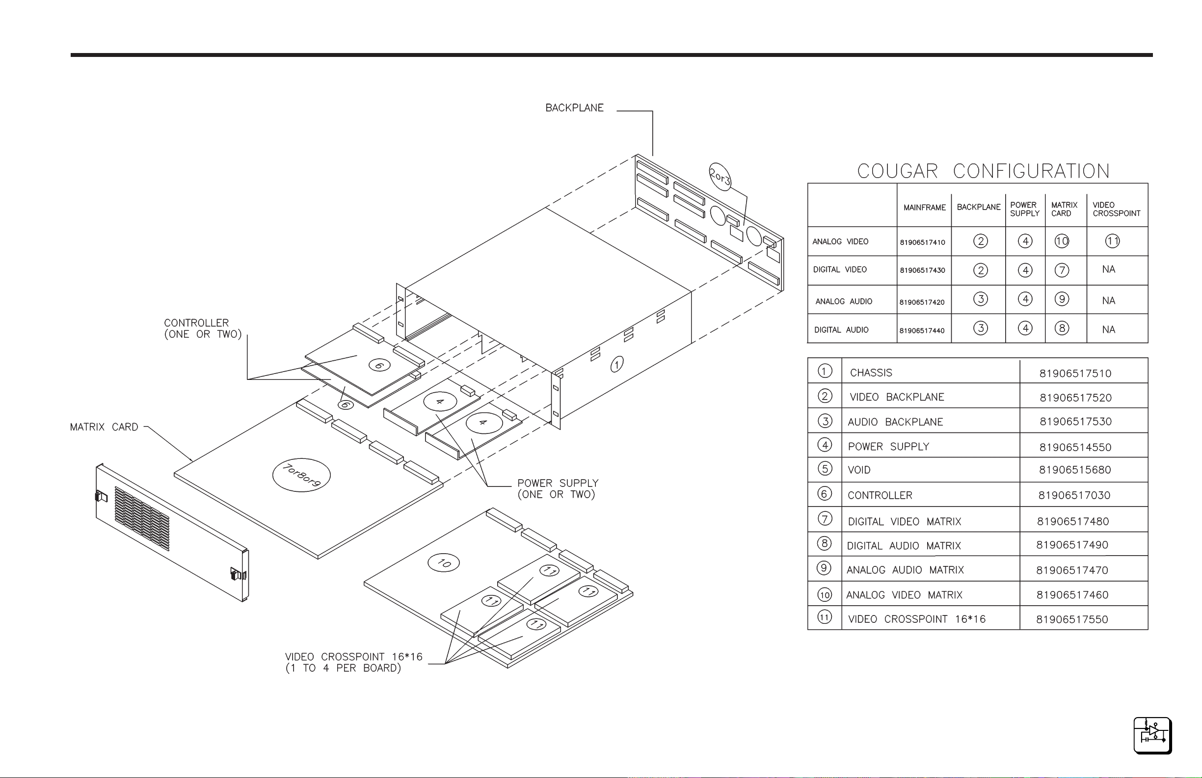
To install the System Controller Card(s) in the Cougar Digital Video Routing Switcher take the following steps while referring to the Cougar Digital
Video Mainframe configuration drawing on page 6.2:
1. Align the first (primary) System Controller Card with the upper set of
circuit card guides in the upper left-hand portion of the Cougar Digital
Video Routing Switcher.
2. Carefully push the System Controller Card into the Cougar Digital
Video Routing Switcher until the circuit card connectors make initial
contact with backplane connectors. At this point, firmly but carefully
continue pushing the controller card into the frame while making sure
the connectors are properly aligned and that no connector pins are
being bent. Continue pushing the controller card until it is in place and
the connectors are firmly mated.
Section 2Installation
3. Align the second (redundant) System Controller Card with the lower
set of circuit card guides in the upper left-hand portion of the Cougar
Digital Video Routing Switcher and repeat step 2.
4. Once the System Controller Card(s) are installed in the Cougar Digital
Video Routing Switcher, install the controller card locking brace and
secure it with a twist nut to hold the controller card(s) in place. NOTE:
The controller locking brace may be removed after shipment to ease
the replacement of System Controller Card(s) when necessary.
2
INSTALLATION
page 2.8
10/95
P/N 81905903440
Page 21

Digital Video
Installation
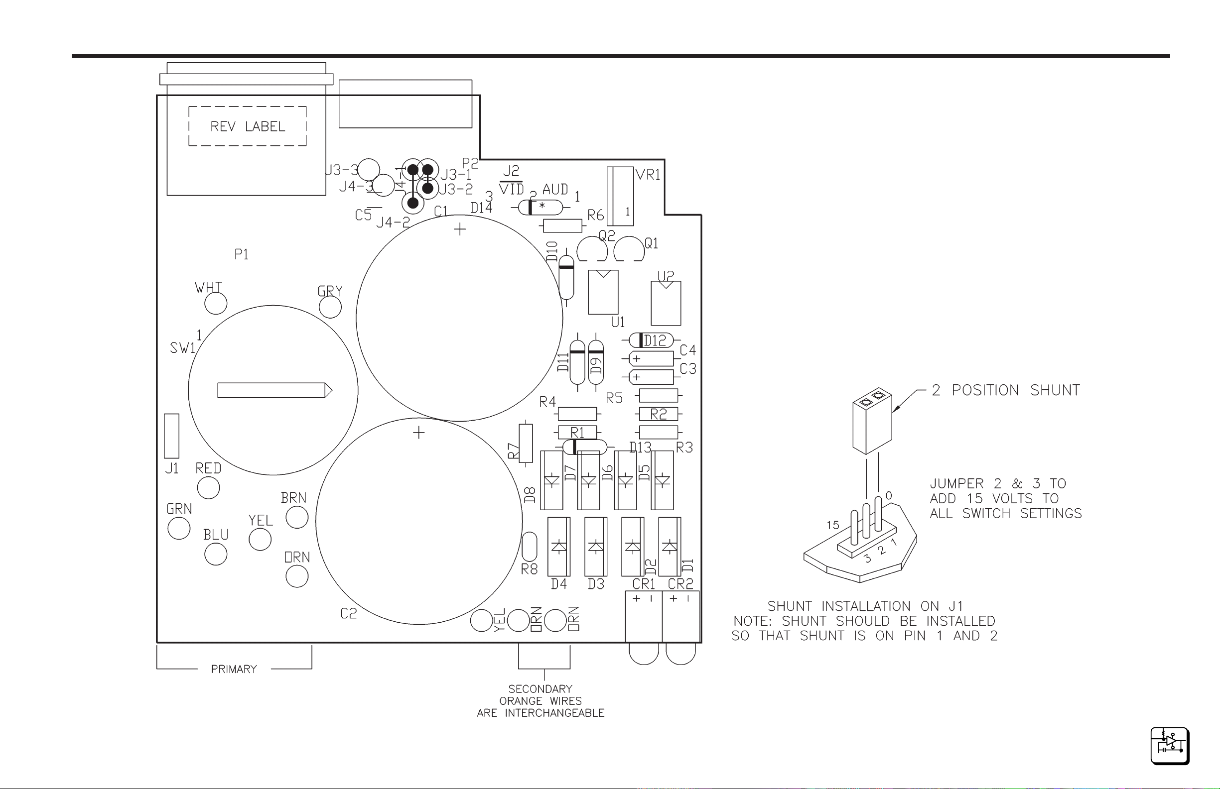
2.10 PS70V Setting Line Voltage
The PS70V Power Supply has an AC Line Select Switch that allows you
to select the required line voltage range. This switch is accessed by removing the plug-in power supply from the switcher, if the power supply is
already installed. Be sure to disconnect the AC power cord before removing the power supply from the switcher. A separate jumper, located under
the plastic safety cover surrounding the switch is used to add 15 volts to
each switch setting. Using only the switch, the nominal (± 10%) input AC
line voltages available are 100, 120, 140, 200, 220, and 240. If the jumper
is also moved, these voltages become 115, 135, 155, 215, 235, and 255.
Be sure the AC Line Select Switch and jumper are set to the correct
positions before powering up the video routing switcher.
Access is provided to the jumper by removing the two screws that secure
the cover. These screws also secure the PC board to the mounting tray.
Be sure to replace both screws. Tighten securely but avoid cracking the
plastic cover.
Section 2
Caution: To avoid electrical shock, insure that the filter capacitors are
completely discharged before changing the switch or jumper selection.
2.11 PS70V Power Supply Installation
The PS70V Power Supply(s) are installed in the upper right-hand portion
of the Cougar Digital Video Routing Switcher. The Cougar Digital Video
Routing Switcher is designed for the installation of up to two PS70V
Power Supplies. If only one PS70V Power Supply is to be installed in the
Cougar Digital Video Routing Switcher, install it in the left-hand position.
To install the PS70V Power Supply or to install the PS70V Power Supplies
in the Cougar Digital Video Routing Switcher take the following steps while
referring to the Cougar Digital Video Mainframe configuration drawing on
page 6.2:
1. Align the primary power supply with the left-hand set of circuit card
guides in the upper right-hand side of the Cougar Digital Video Routing
Switcher.
10/95
P/N 81905903440
page 2.9
2
INSTALLATION
Page 22

Digital Video
Section 2Installation
2.11 PS70V Power Supply Installation Continued:
2. Carefully push the power supply into the switcher until the power
supply connector makes initial contact with backplane power connector. At this point, firmly but carefully continue pushing the power supply
into the switcher while making sure the connectors are properly aligned
and that no connector pins are being bent. Continue pushing the
power supply until it is in place and the connectors are firmly mated.
3. Align the secondary (redundant) power supply with the right-hand set
of circuit card guides in the upper right-hand side of the Cougar Digital
Video Routing Switcher.
4. Repeat step two.
5. If the Cougar Digital Video Routing Switcher is being shipped, install
the two power supply retainer screws through the top of the Cougar
Digital Video Routing Switcher.
2.12 32X32 Digital Video Matrix Card Installation
The 32X32 Digital Video Matrix Card is installed in the lower portion of the
Cougar Digital Video Routing Switcher. To install the matrix board in the
Cougar Digital Video Routing Switcher take the following steps while
referring to the Cougar Digital Video Mainframe configuration drawing on
page 6.2:
1. Align the shield plate of the matrix card with the set of circuit card
guides in the lower portion of the Cougar Digital Video Routing
Switcher.
2. Carefully push the matrix board into the switcher until the circuit card
connectors make initial contact with backplane connectors. At this
point, firmly but carefully continue pushing the matrix card into the
switcher while making sure the connectors are properly aligned and
that no connector pins are being bent. Continue pushing the card until
it is in place and the connectors are firmly mated.
2
INSTALLATION
page 2.10
10/95
P/N 81905903440
Page 23
Digital Video
Installation
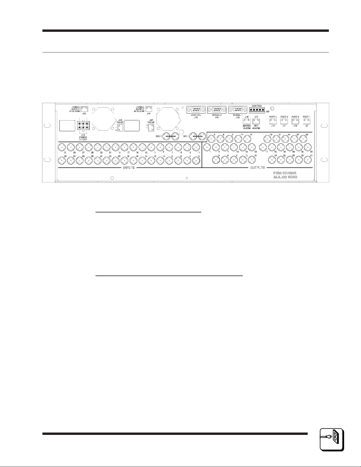
2.13 Rear Panel Connectors
The manual subsections discuss the various system connectors found on
the rear backplane (rear panel) of the Cougar Digital Video Routing
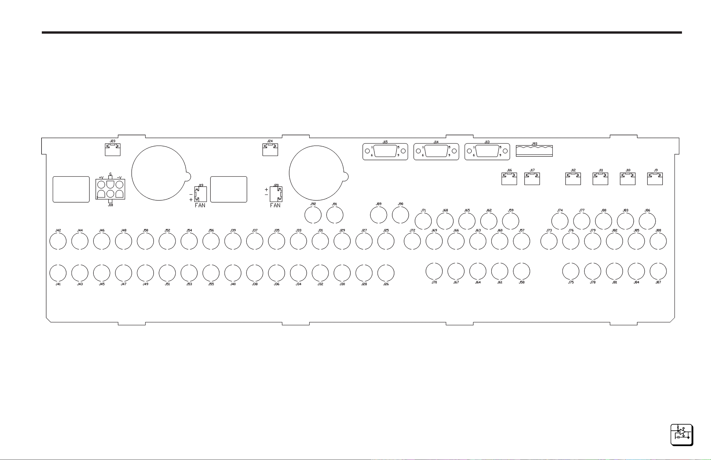
Switcher. Refer to the 32X32 Video Backplane component assembly
drawing on page 6.4 and to Figure 2-7 for a visual references.
Figure 2-7 Cougar Digital Video Routing Switcher Rear View
Section 2
10/95
P/N 81905903440
RCP Panel Connectors (J9-J12)
The RS485 panel port connectors allow the daisy-chained connection of
up 64 remote control panels to the Cougar Digital Video Routing Switcher.
Bidirectional communications between the internally installed System
Controller(s) and the various models of PESA's low cost RCP control
panels are sent and received over RS485 buss.
Serial (CPU Link) Connectors (J13 and J14)
The CPU Link connectors allow serial communications between the internally installed System Controller(s) and up to two external computers. The
System Controller supports asynchronous, bidirectional communications,
at 9600 baud. The protocol used in communication via these ports is a
proprietary protocol developed by PESA for switcher control. The pinout
for CPU link connector is as follows:
PIN NO. DESCRIPTION
1CD
2 RX DATA
3 TX DATA
4 DTR
5 GROUND
6 DSR
7 RTS
8 CTS
9 N/C
page 2.11
2
INSTALLATION
Page 24

Digital Video
2.13Rear Panel Connectors Continued:
Control (PRC) Connectors (J15 and J93)
J15 provides for the connection of an optional external controller to the
Cougar Digital Video Routing Switcher. J93 provides for the connection of
additional Cougar Digital Video Routing Switchers to form up to a 64X64
switching matrix. Both of the control connectors allow for the bi-directional
transmission of data.
The pinout of control connector J15 is as follows:
PIN NO. DESCRIPTION
1 GROUND
2 RX+ DATA
3 TX- DATA
4 GROUND
5 SPARE
6 GROUND
7 RX- DATA
8 TX+ DATA
9 GROUND
Section 2Installation
The pinout of control connector J93 is as follows:
PIN NO. DESCRIPTION
1 TX+ DATA
2 TX- DATA
3 GROUND
4 RX+ DATA
5 RX- DATA
For PRC communications, the user should use a direct pin-for-pin cable
for interfacing between the System Controller and the peripheral equipment. DO NOT use a "NULL MODEM" cable.
CPU Alarm Connector (J16)
Not used.
2
INSTALLATION
page 2.12
10/95
P/N 81905903440
Page 25

Digital Video
Installation
2.13Rear Panel Connectors Continued:
Matrix Card Alarm Connector (J17)
An alarm circuit has been provided in the 32X32 Digital Video Matrix
Card's circuitry. This circuit acts as a switch to trigger an optional external
alarm in the event of a controller fault or failure. The controller alarm
circuit supplies a contact closure but does not provide a voltage to the
external alarm. The Matrix Card Alarm Connector, located on the backplane, allows connection of the Matrix Card Alarm.
Power In/Out Connector (J18)
Power can be supplied to the Cougar Digital Video Routing Switcher by
the use of an externally mounted power supply, by the use of an internal
PS70V Power Supply, or by the use dual internal PS70V Power Supplies.
The use of at least one PS70V Power Supply per Cougar Frame is required to prevent overload conditions. The DC Power Connector can be
used as DC power input (external power supply) or as DC power output
(internal power supply or power supplies) to allow the Cougar Digital Video
Routing Switcher to power additional video equipment items. External
power supplies must be diode isolated from the internal power supply. An
1N5821 or equivalent type diode may be used for this purpose.
Section 2
Power Supply Alarm Connectors (J23 and J24)
An alarm circuit has been provided in the PS70V Power Supply's circuitry.
This circuit acts as a switch to trigger an optional external alarm in the
event of a failure in the power supply or of the external 110VAC (220VAC
for the international version) source. The alarm circuit supplies a contact
closure but does not provide a voltage to the external alarm. The alarm
connectors, located on the backplane, allow connection of external power
supply alarms.
Reference (Sync) Connectors (1 and 2)
The sync connectors are used to connect an external sync signal to the
Cougar Digital Video Routing Switcher. The sync signal may be either a
color black or composite video signal. The use of an external sync signal
allows switch changes to be accurately timed in the vertical interval. The
sync connectors are loop-thru connectors and must be terminated with 75
ohms if looping is not used.
10/95
P/N 81905903440
page 2.13
2
INSTALLATION
Page 26

Digital Video
2.13Rear Panel Connectors Continued:
Video Input and Output Connectors
There are 32 BNC video input connectors and 32 BNC video output connectors located on the Cougar Digital Video Routing Switcher's rear panel.
These connectors allow the connection of the digital video sources (input
connectors) and digital video destinations (output connectors) to the
Cougar Digital Video Routing Switcher. The digital video input connectors
are internally terminated into 75 ohms.
2.14 System Connections
Once the Cougar Digital Video Routing Switcher is installed in the equipment rack, system connections can be made. Use the following guide to
insure that the Cougar Digital Video Routing Switcher system interconnections are properly connected and that the control, power, sync, and digital
video cables are correctly installed.
Section 2Installation
Connection Guide
1. Connect the external sync sources to the reference inputs using
Belden 8281 coaxial cable or equivalent. Be sure to properly terminate
the external sync sources into 75 ohms.
2. Connect the primary external computer to the Serial 1 Connector using
a 9-pin RS232 cable. Please note that this connection has to be made
in order to configure the internal System Controller using the Control
System software package. If a secondary external computer is to be
used, connect it to the Serial 2 connector.
3. If additional Cougar Digital Video Routing Switchers are to be utilized
as part of the switching matrix, connect J93 on the primary Cougar
Digital Video Routing Switcher to J93 on the other Cougar Digital
Video Routing Switchers using 5-pin ribbon cables.
4. If an external controller is to be utilized to control the Cougar Digital
Video Routing Switcher, connect the external controller to J15 using 9pin RS232 cable.
2
INSTALLATION
page 2.14
5. Connect the RCP control panels to the RS485 ports (J9-J12) using
twisted pair cables. The connect to the control panel may be daisy
chained.
10/95
P/N 81905903440
Page 27

Digital Video
Installation
2.14 System Connections Continued:
Connection Guide Continued:
6. If desired, connect an external alarm to the Matrix Board Alarm Con-
nector (J17).
7. If desired, connect an external backup power supply to the power in/out
connector (J18) or use the Cougar Digital Video Routing Switcher to
power other video equipment by looping a power cable between J18
and the additional video equipment.
8. If desired, connect an external alarm to the power supply #1 alarm
connector (primary power supply). If a secondary (redundant) power
supply is installed in the Cougar Digital Video Routing Switcher, connect an external alarm to the power supply #2 alarm connector, if
desired.
Section 2
9. Connect the digital video sources to the video inputs using Belden
8281 coaxial cable or equivalent 75 ohm coaxial cable.
10.Connect the video outputs to the digital video destinations using
Belden 8281 coaxial cable or equivalent.
10/95
P/N 81905903440
page 2.15
2
INSTALLATION
Page 28

Digital Video
Operations Section 3
3.1 Operation of the Cougar Digital Video Routing Swit.
General
The operation of the Cougar Digital Video Routing Switcher consists of
periodically monitoring the 32X32 Digital Video Matrix Card LEDs. The
matrix card LEDs and their proper indications are discussed in the following manual sections.
3.2 Regulator Fault LED (Red)
The Regulator Fault LED (CR5) is utilized to visually indicate a regulator
problem on the matrix card. A problem with the power supply or regulator
circuits will cause this LED to light. However, in the event of a total power
outage this LED will be rendered inoperable.
3.3 CPU Fault LED (Red)
The CPU Fault LED (CR6) is utilized to visually indicate a microprocessor
problem on the matrix card. A problem with the CPU or controller circuits
will cause this LED to light.
3.4 Power OK LED (Green)
The Power OK LED (CR7) on the front edge of the matrix card is utilized
to visually indicate that the proper power supply voltage is being supplied
to the card. A decrease in the brightness of this LED indicates an approximate 12% drop in voltage and should be checked. A 25% drop in voltage
will cause the LED to extinguish.
3.5 32X32 Digital Video Matrix Card Adjustments
There are no user adjustments on the 32X32 Digital Video Matrix Card.
10/95
P/N 81905903440 page 3.1
3
OPERATION
Page 29

Digital Video
Functional Section 4
4.1 Introduction
General
The Cougar Digital Video Routing Switcher provides switching of 32 video
inputs to 32 video outputs while supporting multiple data bit rates. The
data rates supported included: (D1, 270 Mbit/s), (D2 or D3, NTSC @ 143
Mbit/s), (D2 or D3, PAL @ 177 Mbit/s), and the proposed (compressed,
16:9 HDTV @ 360 Mbit/s).
4.2 32X32 Digital Video Matrix Card
The 32X32 Digital Video Matrix Card contains a 32X32 matrix consisting
of several main circuits. This discussion will be broken down to the main
circuits as they are found on the schematics in Section 6 (Schematics).
Control
The microprocessor controller (U56) is used to interface switch commands
from the PRCI control port (U63) to the switch matrix and return status information to the controller. Matrix input, output , and level coding is read
from the backplane through U50 thru U53. U65, U55, and U59 provide address decoding for the 32X32 Digital Video Matrix Card.
U58 and U57 comprise the nonvolatile RAM for the processor. C242 provides memory backup voltage for approximately seven days as long as
the matrix card is not removed from the Cougar Frame. CR6 is utilized by
the processor on the 32X32 Digital Video Matrix Card to indicate a fault
condition.
Two external sync signals are used for timing switches as set by S1. The
external sync can be color black or composite sync. U69 and U71 decode
the composite signal to an even/odd field signal which is used by the microprocessor.
Crosspoint Matrix
U49 is the 32X32 crosspoint matrix switch. A0-A4 select the output buss
to control. D0-D4 select the input to be switched to the selected output.
CS0 latches the data into a hold register, then VREF1 latches the data
into the crosspoint control registers.
4/98
P/N 81905903440
page 4.1
4
FUNCTIONAL
DESCRIPTI ON
Page 30

Digital Video
4.2 32X32 Digital Video Matrix Card Continued:
Input Equalizers
The 32 video inputs are terminated into 75 ohms on the matrix card. U1
thru U16 and U78 thru U93 provide automatic input cable equalization for
the inputs. The inputs are equalized for 0 to 240 meters of Belden 8281 or
equivalent cable for data rates up to 270Mbit/s and 0 to 150 meters for
data rates up to 360Mbit/s.
Output Drivers
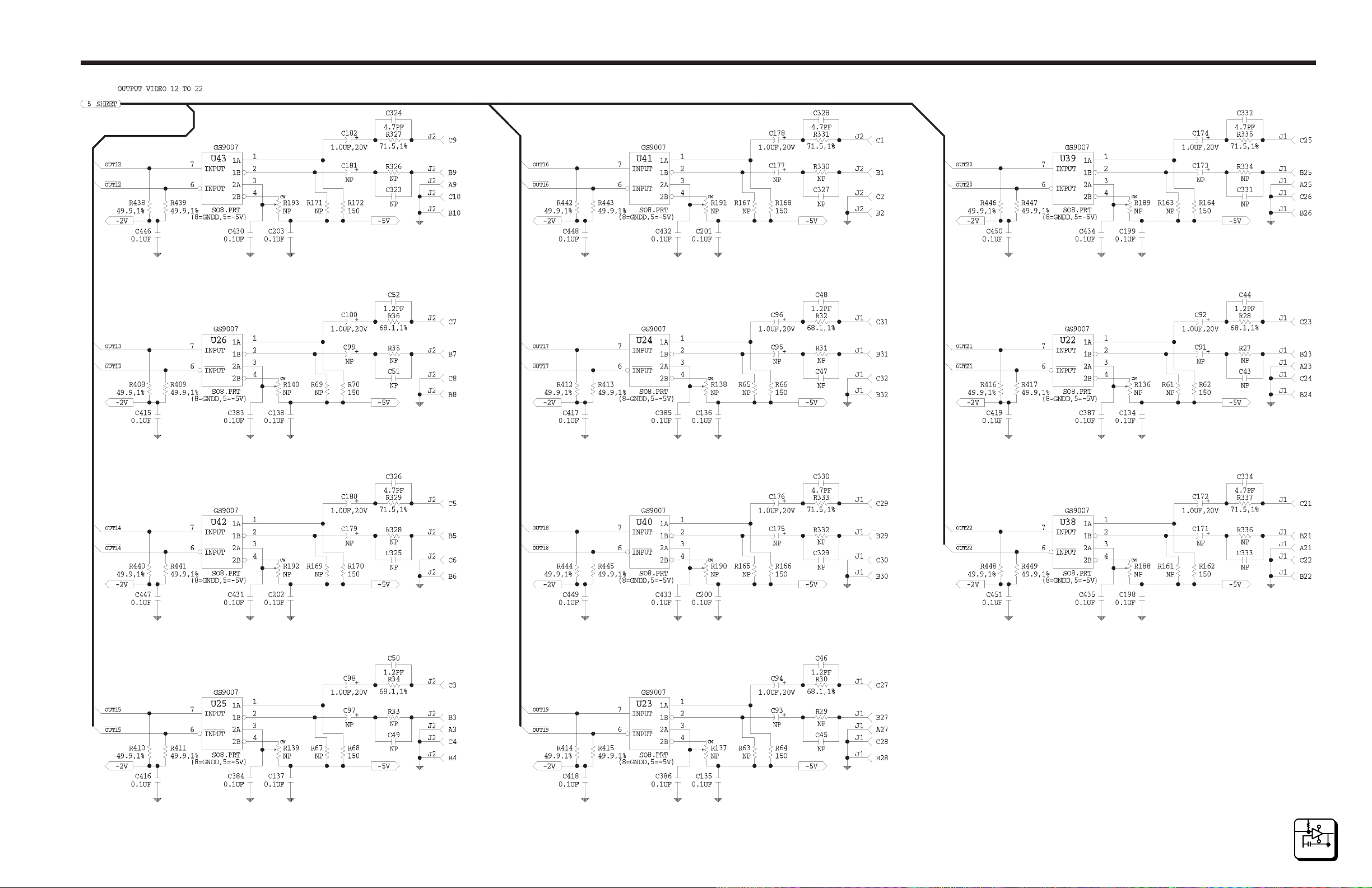
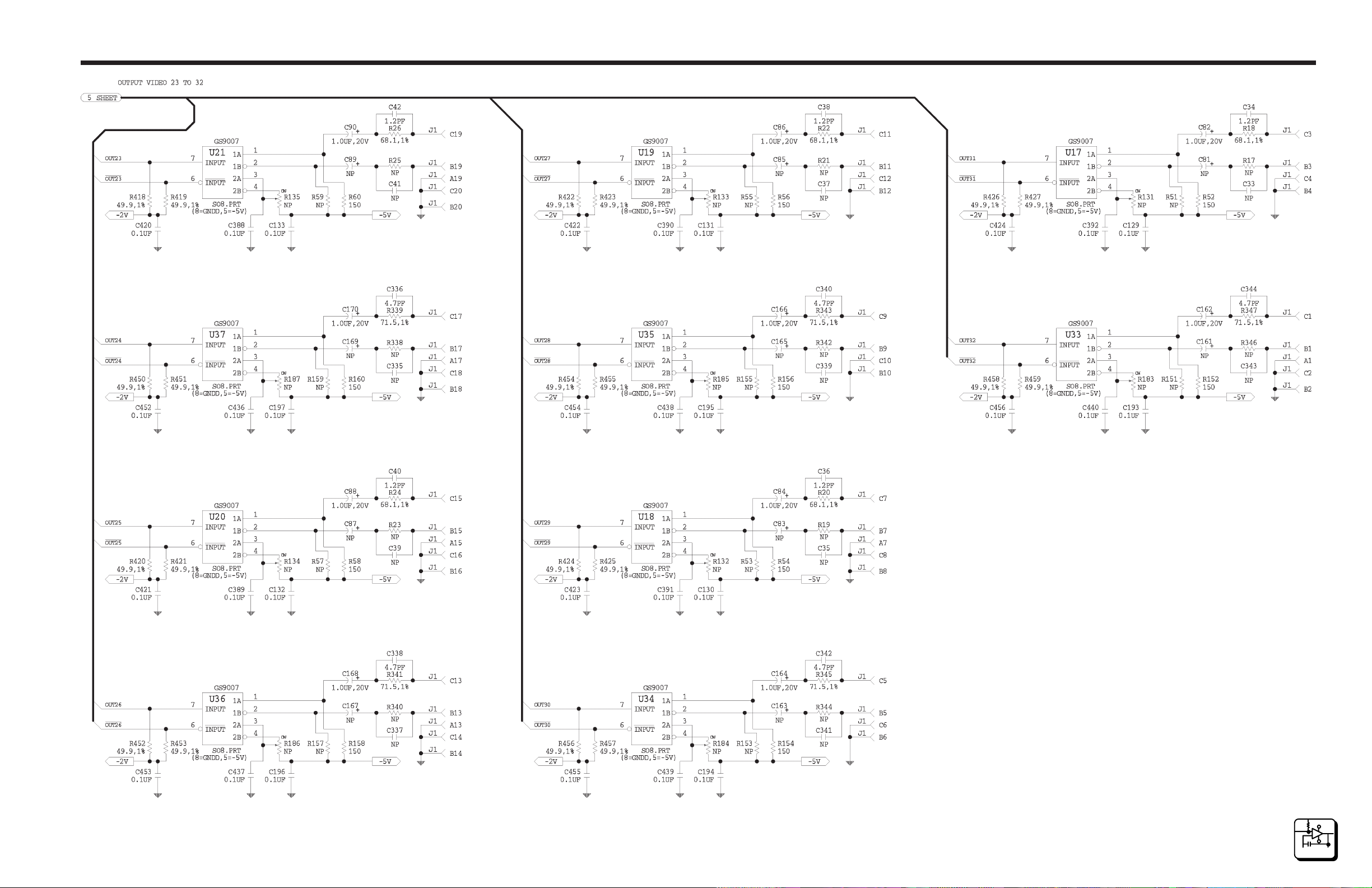
U17 thru U48 are used to drive the outputs for the 32X32 Digital Video
Matrix Card.
Power Regulators
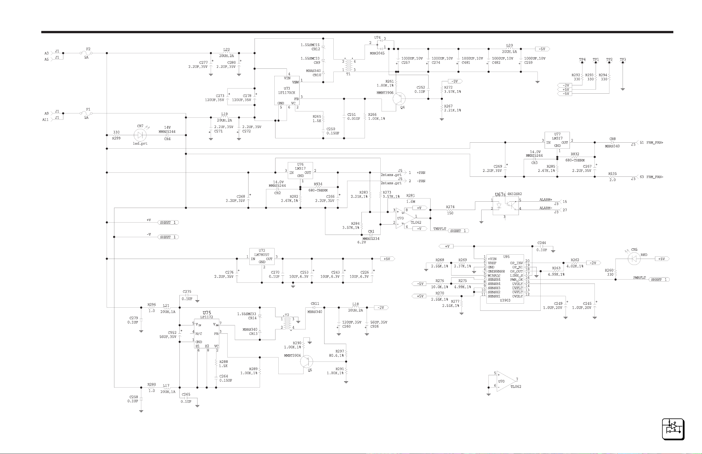
U73 is a switching regulator that creates -5.0 volts @ 5 amps to power the
crosspoint matrix, input, and output ICs. U75 is a switching regulator that
creates -2.00 volts @ 2 amps to power the video transmission line terminators. U72 is a +5 volt regulator which is used to the control logic.
Section 4Functional
U77 provides power to the backplane to drive the chassis fan. U76 provides power to the heatsink fan used to cool U49. U95 monitors all primary circuit card voltages for out of voltage range conditions (±15%). If a
fault is sensed CR5 will light and controller will report the error condition.
CR7 indicates that power is applied to the 32X32 Digital Video Matrix
Card.
4.3 PS70V Power Supply
The PS70V Power Supply is an unregulated power source that supplies ±
voltages to the Cougar Digital Video Frame.
Each power supply produced by PESA has an AC Select Switch that allows you to select the required voltage range. This switch is accessed by
removing the plug-in supply. Insure that power is off before changing the
switch setting. A separate jumper, located under the plastic safety cover
surrounding the switch is used to add 15 volts to each switch setting. Using only the switch, the nominal (± 10%) AC line voltages available are
100, 120, 140, 200, 220, and 240. If the jumper is also moved, these voltages become 115, 135,155, 215, 235, and 255.
4
FUNCTIONAL
DESCRIPTION
page 4.2
4/98
P/N 81905903440
Page 31

Digital Video
Functional Section 4
4.3 PS70V Power Supply Continued:
Access is provided to the jumper by removing the two screws that secure
the cover. These screws also secure the PC card to the mounting tray. Be
sure to replace both screws. Tighten securely but avoid cracking the plastic cover.
Note: To avoid electrical shock, insure that the filter capacitors are completely discharged.
Circuit Description
Input fuses provide overcurrent protection from internal faults and output
overloads. If a fuse opens, correct the overcurrent condition then replace
the fuse(s). Both sides of the line are fused.
The AC selector switch interconnects the transformer primaries in series
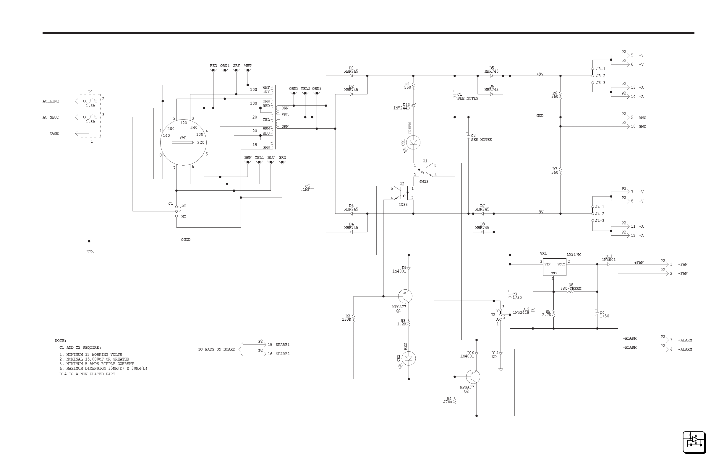
and/or parallel combinations to provide the proper ratio for the input line
voltage.
The secondaries drive full wave rectifiers with capacitor input filters providing positive and negative voltages with respect to ground.
After the filters, series diodes are used to allow supplies to be paralleled
for redundancy. The diodes assure that one supply cannot load the output
of the others in case of a shorted diode or capacitor.
A temperature sensing circuit controls the fan speed according to the air
temperature and the temperature of the rectifier diodes. The fan usually
runs at half speed at normal temperature (25°C).
A circuit senses the voltages across the filter capacitors. If the combined
voltages decrease by approximately 25% from normal, the green LED is
turned off. The red LED, located on the PC card, is then lit and the alarm
closure activated at the same time. The green LED, located on the front
panel, serves as a rough indicator of output voltage; it dims as the combined positive and negative voltages decrease.
These supplies are unregulated and follow input line changes and output
load variations.
4/98
P/N 81905903440
page 4.3
4
FUNCTIONAL
DESCRIPTI ON
Page 32

Digital Video
Maintenance Section 5
5.1 Introduction
This section will cover the maintenance, troubleshooting, and repair of the
Cougar Digital Video Routing Switcher.
NOTICE
THIS EQUIPMENT CONTAINS STATIC SENSITIVE DEVICES. IT IS RECOMMENDED
THAT A GROUNDED WRIST STRAP AND MAT BE USED WHILE MAKING REPAIRS
OR ADJUSTMENTS.
5.2 General
The Cougar Digital Video Routing Switcher is designed to produce the
proper digital video levels throughout the frame. There are no adjustments
on the 32X32 Digital Video Matrix Card and the need for regular
maintenance is minimal.
5.3 Test Equipment
The test equipment recommended for servicing the Cougar Digital Video
Routing Switcher and its associated circuit cards is listed below. Equivalent test equipment may be used.
Digital Voltmeter
Digitizing Oscilloscope
Pattern Generator
Oscilloscope
75 Ohm Termination
10/95
P/N 81905903440 page 5.1
5
MAINTENANCE
Page 33

Digital Video
5.4 Preventive Maintenance
Use the following guidelines for general preventive maintenance:
• Keep the inside of the equipment items clean, especially if your facility
is subject to dust or dirt in the atmosphere. Use compressed air, an
antistatic cloth, or a gentle vacuum to clean the frame and internal
components.
• Observe proper procedures for preventing electrostatic discharge
when cleaning the units, and when inserting and removing cards.
Ensure that all tools and personnel handling individual components are
properly grounded.
• Avoid covering the front grille for any extended period. Blocking the
front grille will block the air flow through the fan and may overheat the
internal circuit cards.
Section 5Maintenance
5.5 Maintenance
The Cougar Digital Video Routing Switcher and its associated circuit cards
are designed and manufactured to give long, trouble free service with
minimum maintenance requirements. If problems do occur, follow the
troubleshooting procedure provided in this section. If additional technical
assistance is required, refer to the General Assistance and Service information in the front of the manual. Section 6 contains component layout
drawings and schematics for assistance in troubleshooting and Section 7
contains the lists of replacement parts for repairing the Cougar Digital
Video Routing Switcher and its associated circuit cards.
5.6 Corrective Maintenance
The following paragraphs provide information to assist the servicing technician in maintenance of the Cougar Digital Video Routing Switcher and
its associated circuit cards.
Factory Repair Service
5
MAINTENANCE
If desired, equipment or boards may be returned to the factory (transportation prepaid) for repair. Refer to the General Assistance and Service
Information Sheet in the front of this manual. Call the PESA Service
Department (the phone number is listed on the Service Information Sheet)
for a RMA number before shipping an equipment item.
10/95
P/N 81905903440page 5.2
Page 34

Digital Video
Maintenance Section 5
5.6 Corrective Maintenance Continued:
Factory Repair Service Continued:
NOTE
PACK THE EQUIPMENT SECURELY AND LABEL WITH THE CORRECT ADDRESS.
PROPER PACKAGING SAVES MONEY. THE SMALL AMOUNT OF EXTRA CARE AND
TIME IT TAKES TO CUSHION A PART OR UNIT PROPERLY MAY PREVENT COSTLY
DAMAGE WHILE IN TRANSIT. MAKE CERTAIN THAT THE ADDRESS IS BOTH LEGIBLE AND COMPLETE. FAILURE TO DO SO OFTEN RESULTS IN DELAY OR EVEN
LOSS.
Troubleshooting
The best troubleshooting tool is a familiarity with the equipment and a
through understanding of its operation. Before troubleshooting the Cougar
Digital Video Routing Switcher or its associated circuit cards review
Sections 3 and 4 of this manual. Use the functional descriptions and
adjustment procedures to quickly locate problems.
• If a problem is suspected with an individual circuit card, first swap out
the card and recheck the system for the problem. If the problem can
be isolated to the card , and your facility is equipped for component
level repair, proceed with repairs using the schematics provided in
Section 6 of this manual.
NOTE
BEFORE PROCEEDING WITH COMPONENT LEVEL REPAIR MAKE SURE THE EQUIPMENT IS OUT OF WARRANTY. REPAIRING EQUIPMENT COVERED BY A WARRANTY
WILL VOID THE WARRANTY.
10/95
P/N 81905903440 page 5.3
5
MAINTENANCE
Page 35

Digital Video
5.6 Corrective Maintenance Continued:
System Checks
Prior to troubleshooting the Cougar Digital Video Routing Switcher the
following basic system checks should be performed.
1. Verify the AC circuit condition. Ensure the unit is receiving the correct
voltage from the main AC power source.
2. Check all line fuses and power cords.
3. Ensure that all circuit cards are firmly seated
4. Ensure all interconnecting cables and connectors are plugged in or
firmly seated.
5. If applicable, ensure main power switch is turned on.
Section 5Maintenance
Replacement Parts
Only parts of the highest quality have been used in the design and
manufacture of the Cougar Digital Video Routing Switcher and its
associated circuit cards. If the inherent stability and reliability are to be
maintained, replacement parts must be of the same quality. A
replacement parts list is provided in Section 7 of this manual. When
replacing parts, avoid using excessive solder on the printed circuit board.
Always make sure that the solder does not short two circuits together. Be
sure the replacement part is identical to the original, and is placed in
exactly the same position with the same lead lengths (if applicable).
5.7 Filter Cleaning
The front door of the Cougar Digital Video Routing Switcher contains an
air filter. The air filter should be cleaned on a periodic basis. Remove the
filter from the door and clean it with soapy water or low pressure air. After
drying reinstall the filter in the door.
5
MAINTENANCE
10/95
P/N 81905903440page 5.4
Page 36

Digital Video
Maintenance Section 5
5.8 PS70V Power Supply
Replacement of the two power supply fuses is accomplished by disconnecting power to the unit, removing the power supply and disassembling
the fuse holder on the rear of the supply. The replacement value of the
power supply fuses is 1.5 Amp (5x20mm) for a line voltage of 115VAC
and 0.8 Amp for a line voltage of 220VAC.
10/95
P/N 81905903440 page 5.5
5
MAINTENANCE
Page 37

Digital Video
6.1 Schematics
General
This section contains the schematic diagrams and parts location diagrams
for the Cougar Digital Video Routing Switcher . Please refer to this section
when troubleshooting the equipment or replacing defective parts.
Description Dwg No. Page No.
Cougar Mainframe CD63-0758 6.2
Cougar Chassis CD63-0759 6.3
32X32 Video Backplane CA25-1281 6.4
32X32 Digital Video Matrix Card CA25-1278 6.8
Power Supply Assembly CD63-0683 6.19
Schematics Section 6
SC33-1281 6.6
SC33-1278 6.10
Power Supply Card CA25-1162 6.20
SC33-1162 6.21
4/98
P/N 81905903440
page 6.1
6
SCHEMATI CS
Page 38
Digital Video
Schematics Section 6
4/98
P/N 81905903440
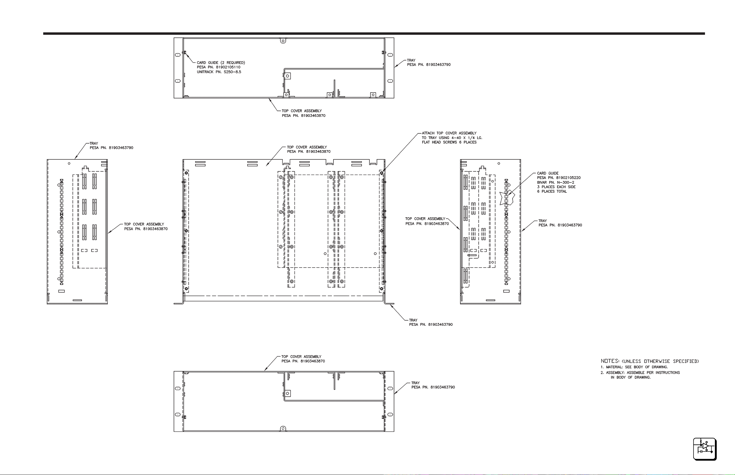
Configuration Drawing • Cougar Mainframe • CD63-0758
page 6.2
6
SCHEM ATI CS
Page 39
Digital Video
Schematics Section 6
4/98
P/N 81905903440
Configuration Drawing • Cougar Chassis • CD63-0759
page 6.3
6
SCHEM ATI CS
Page 40
Digital Video
Schematics Section 6
4/98
P/N 81905903440
Component Assembly (Sheet 1 of 2) • 32X32 Video Backplane • CA25-1281
page 6.4
6
SCHEM ATI CS
Page 41
Digital Video
Schematics Section 6
4/98
P/N 81905903440
Component Assembly (Sheet 2 of 2) • 32X32 Video Backplane • CA25-1281
page 6.5
6
SCHEM ATI CS
Page 42
Digital Video
Schematics Section 6
4/98
P/N 81905903440
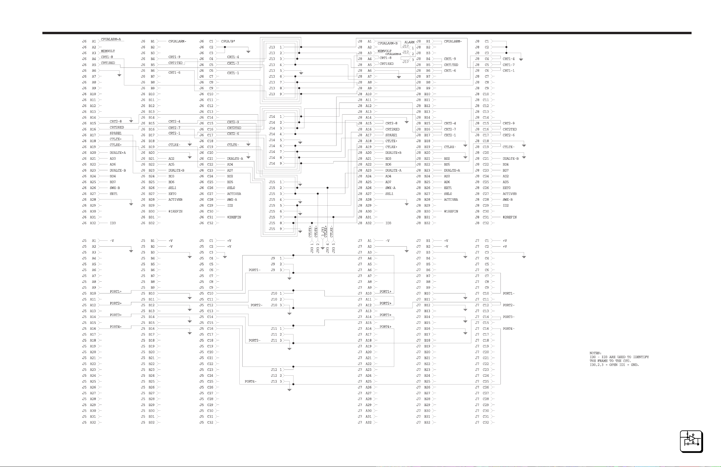
Schematic (Sheet 1 of 2) • 32X32 Video Backplane • SC33-1281
page 6.6
6
SCHEM ATI CS
Page 43
Digital Video
Schematics Section 6
4/98
P/N 81905903440
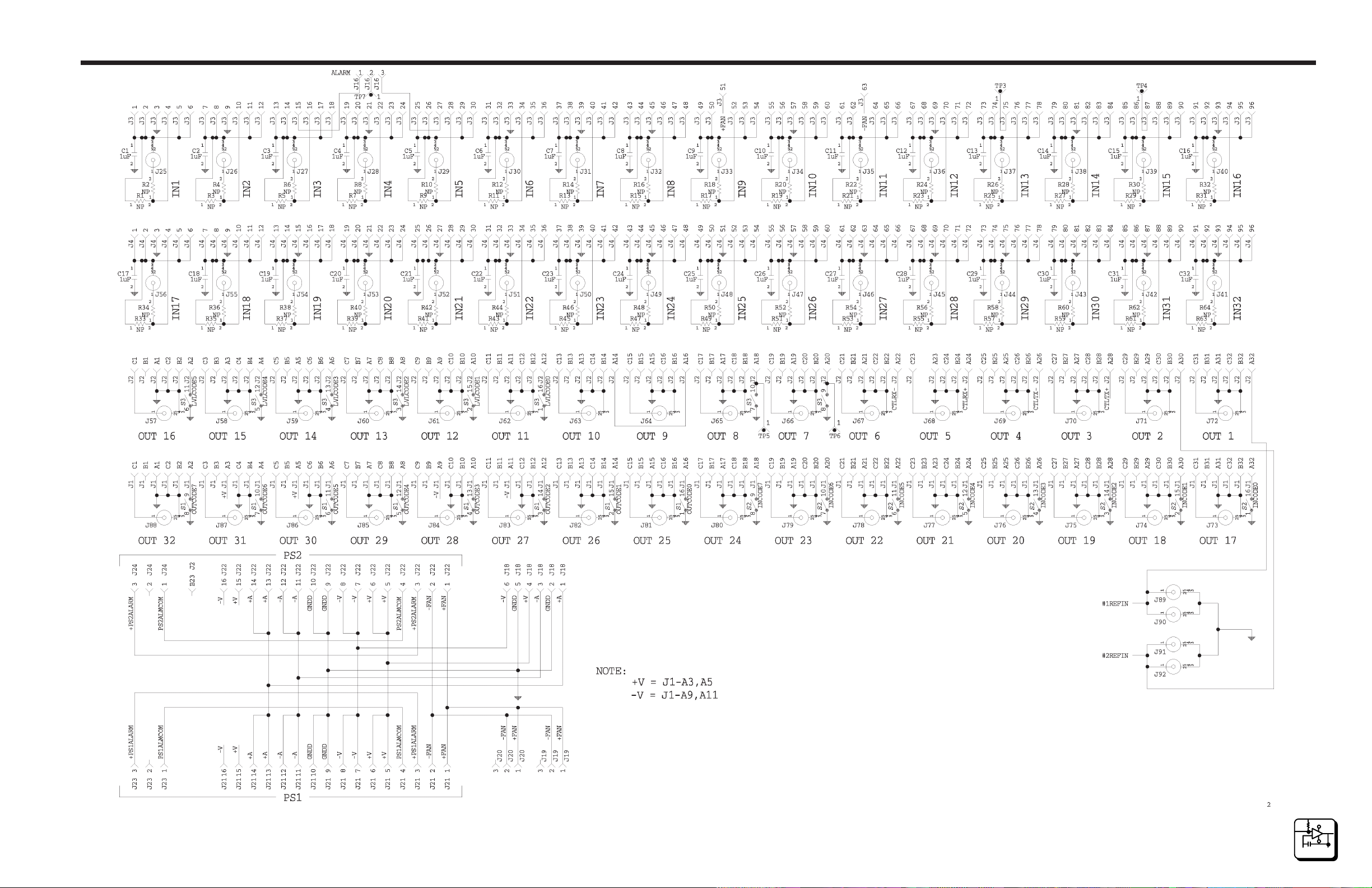
Schematic (Sheet 2 of 2) • 32X32 Video Backplane • SC33-1281
page 6.7
6
SCHEM ATI CS
Page 44
Digital Video
Schematics Section 6
4/98
P/N 81905903440
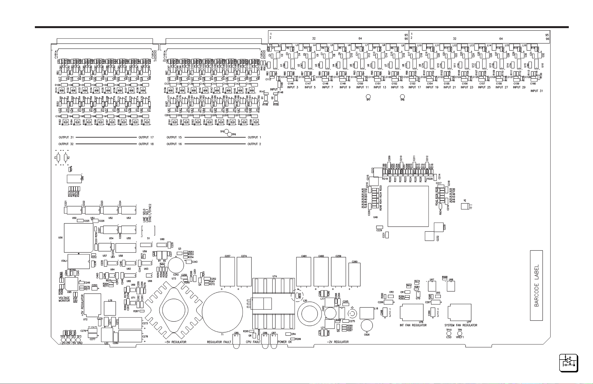
Component Assembly (Sheet 1 of 2) • 32X32 Digital Video Matrix Card • CA25-1278
page 6.8
6
SCHEM ATI CS
Page 45
Digital Video
Schematics Section 6
4/98
P/N 81905903440
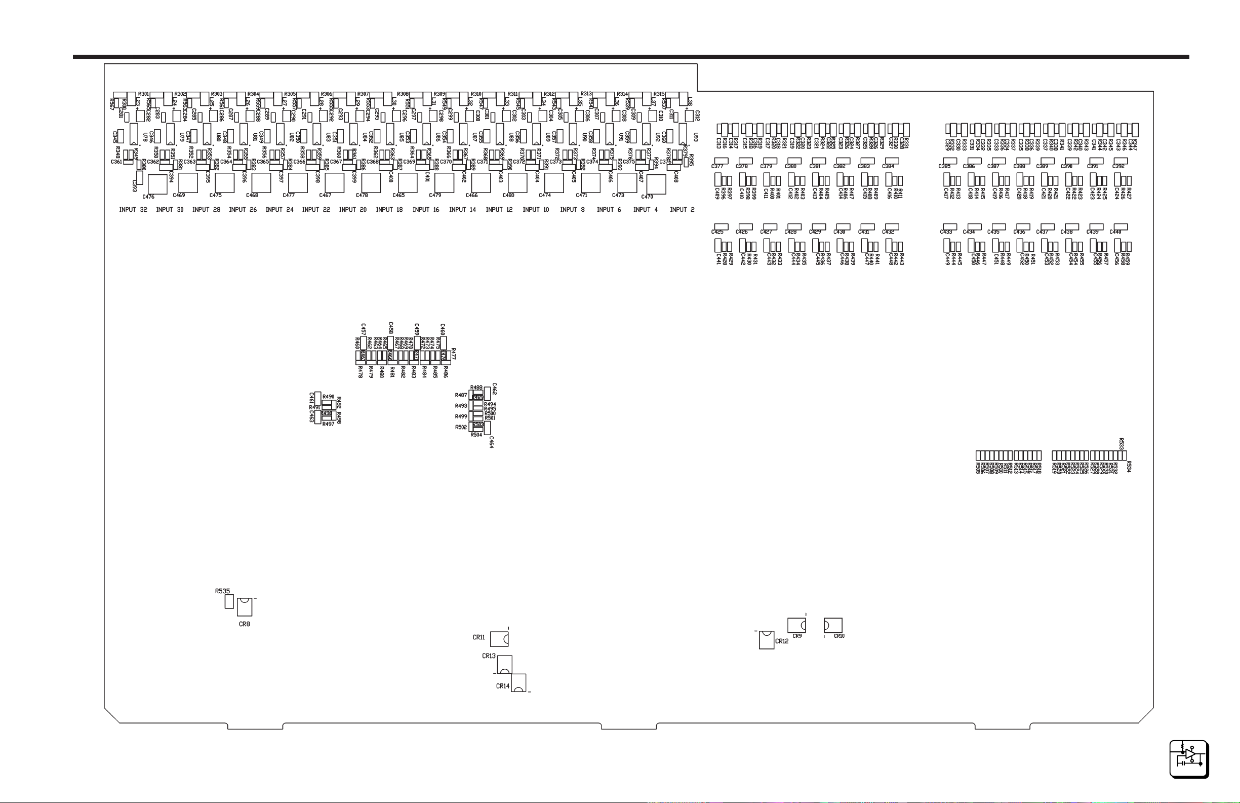
Component Assembly (Sheet 2 of 2) • 32X32 Digital Video Matrix Card • CA25-1278
page 6.9
6
SCHEM ATI CS
Page 46
Digital Video
Schematics Section 6
4/98
P/N 81905903440
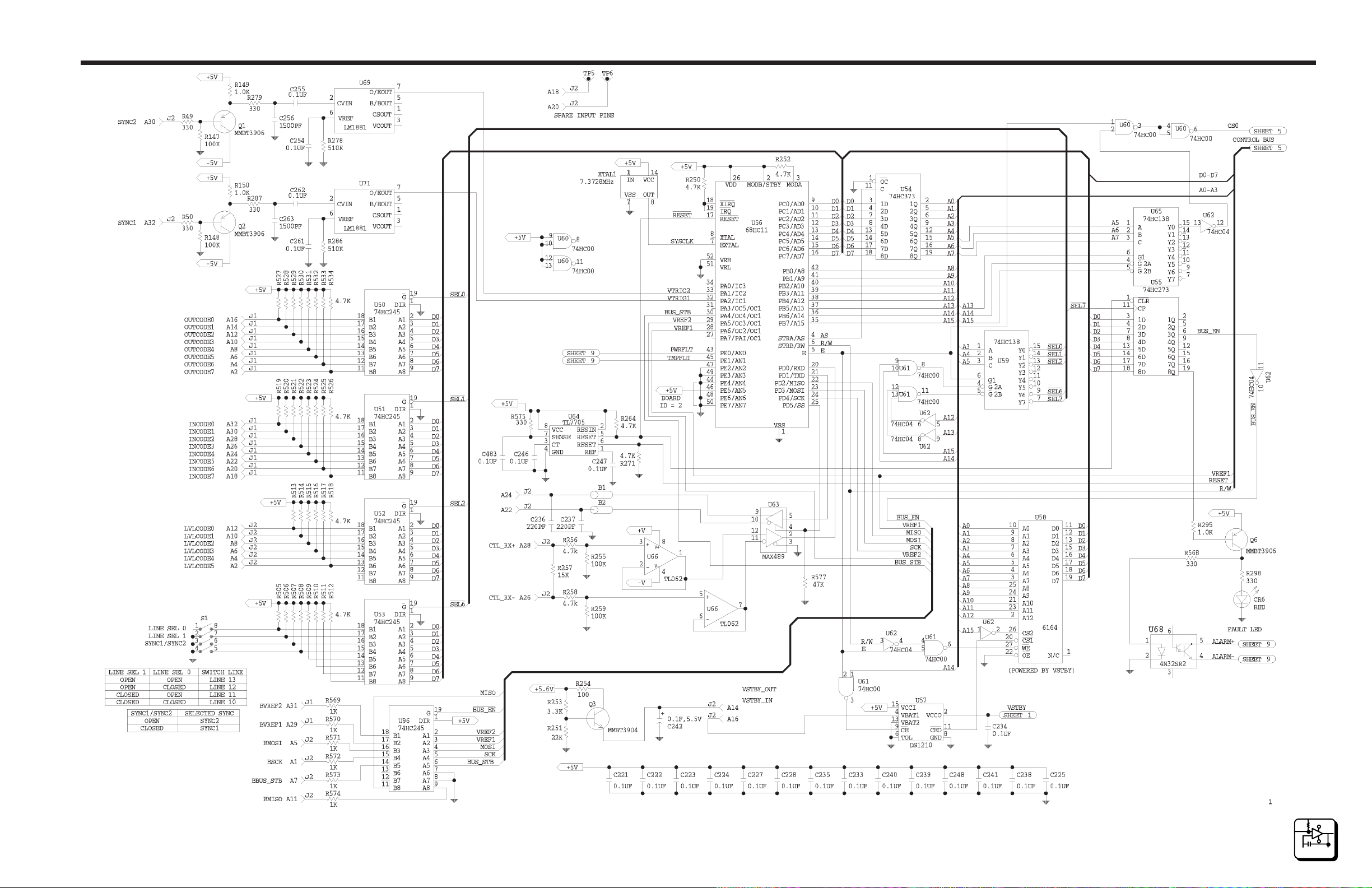
Schematic (Sheet 1 of 9) • 32X32 Digital Video Matrix Card • SC33-1278
page 6.10
6
SCHEM ATI CS
Page 47
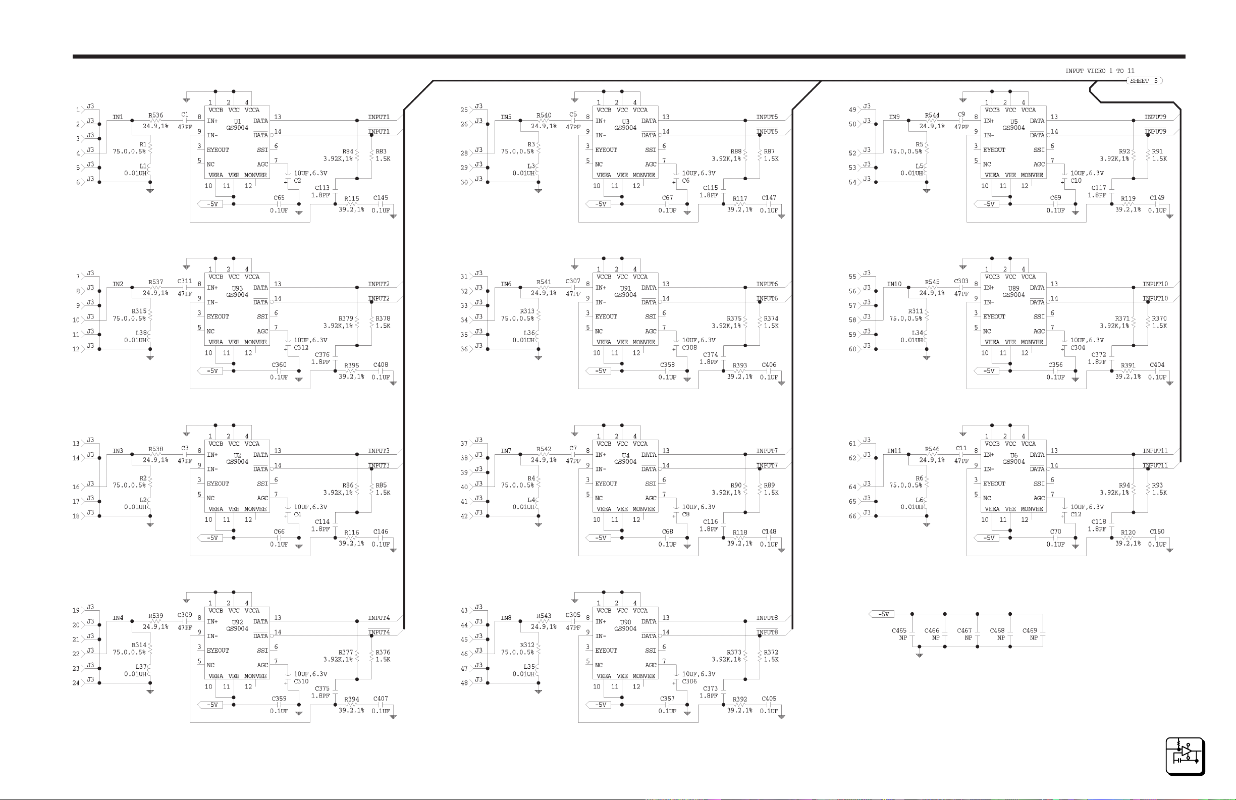
Digital Video
Schematics Section 6
4/98
P/N 81905903440
Schematic (Sheet 2 of 9) • 32X32 Digital Video Matrix Card • SC33-1278
page 6.11
6
SCHEM ATI CS
Page 48
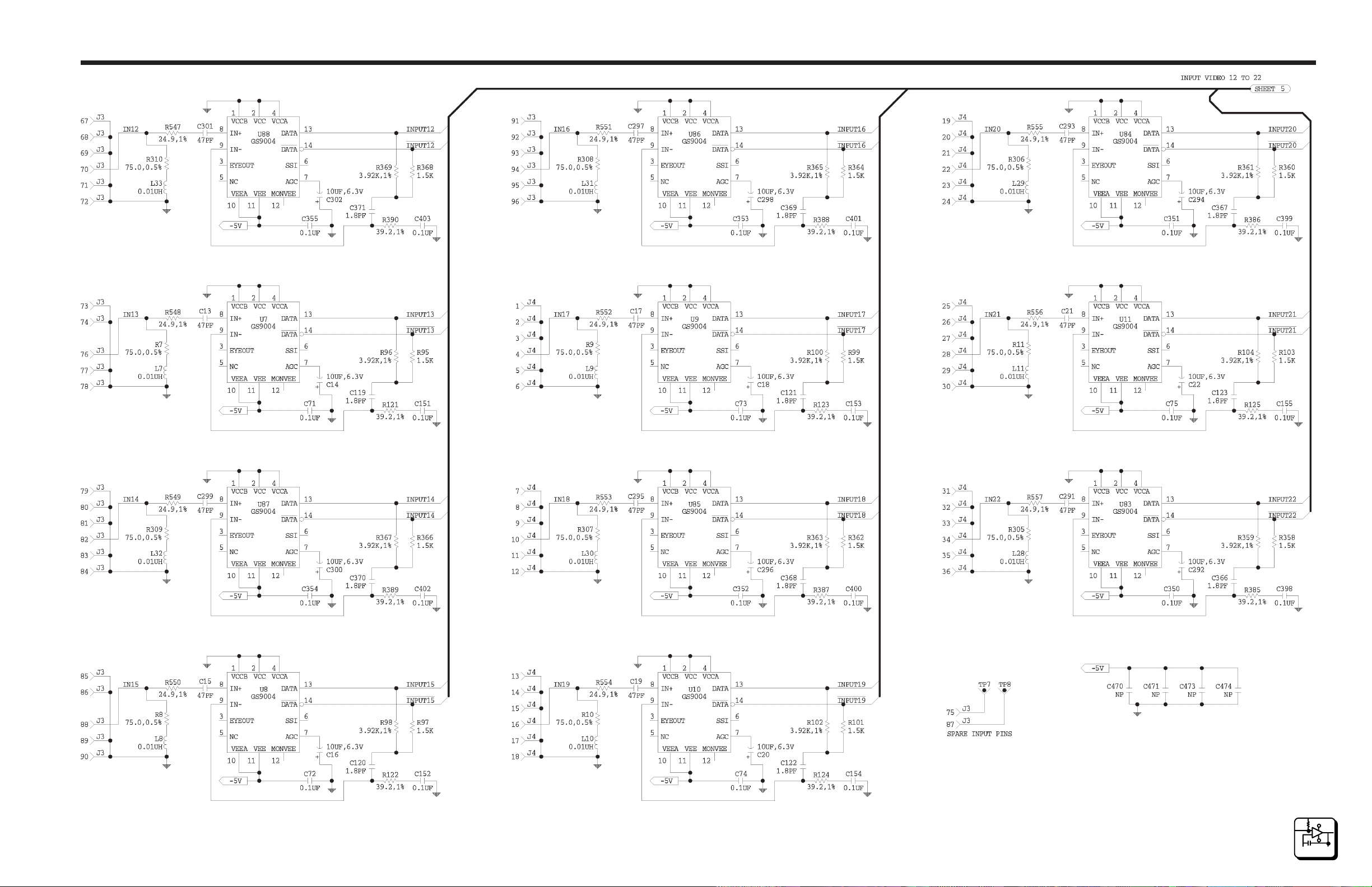
Digital Video
Schematics Section 6
4/98
P/N 81905903440
Schematic (Sheet 3 of 9) • 32X32 Digital Video Matrix Card • SC33-1278
page 6.12
6
SCHEM ATI CS
Page 49
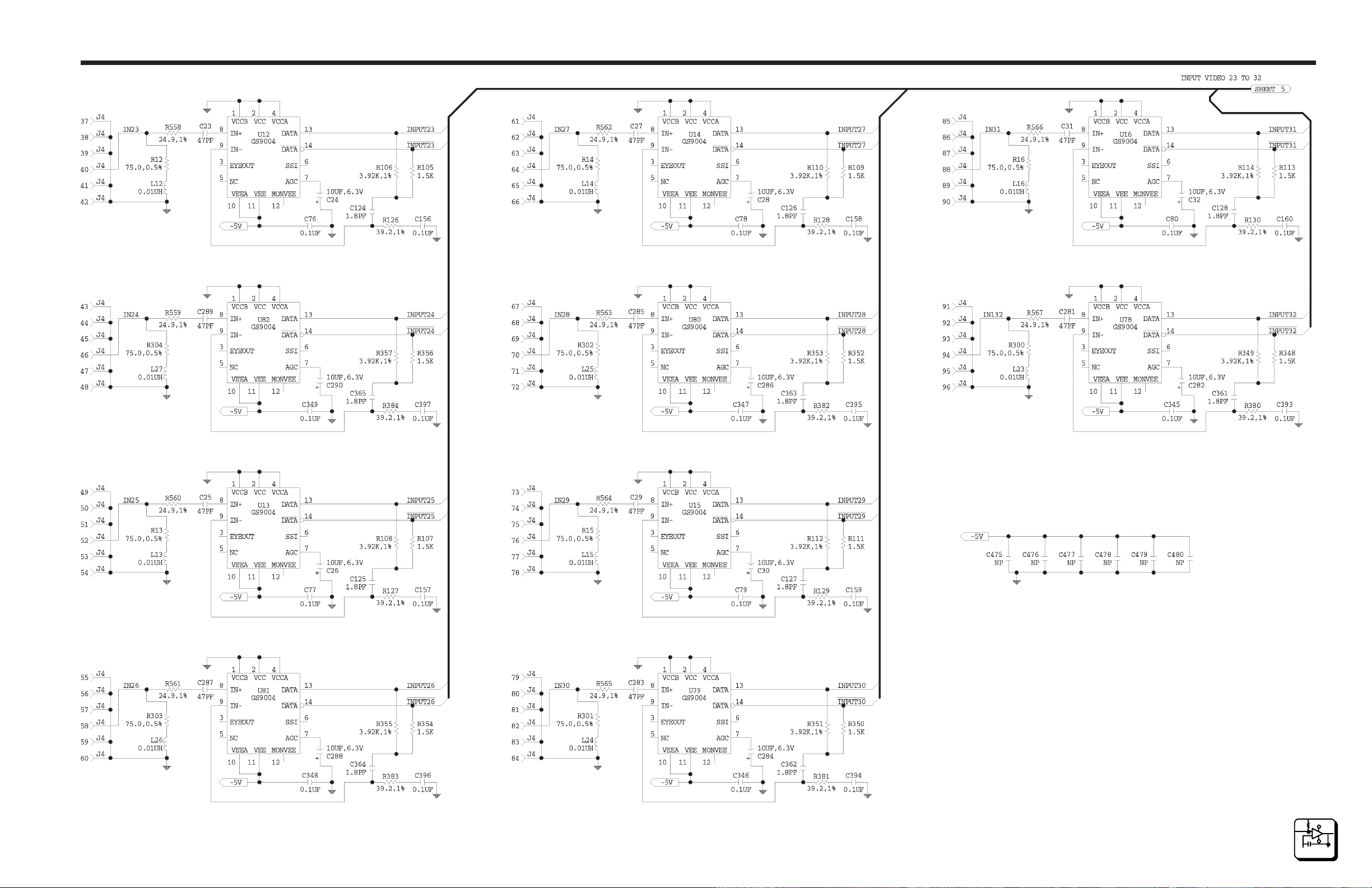
Digital Video
Schematics Section 6
4/98
P/N 81905903440
Schematic (Sheet 4 of 9) • 32X32 Digital Video Matrix Card • SC33-1278
page 6.13
6
SCHEM ATI CS
Page 50
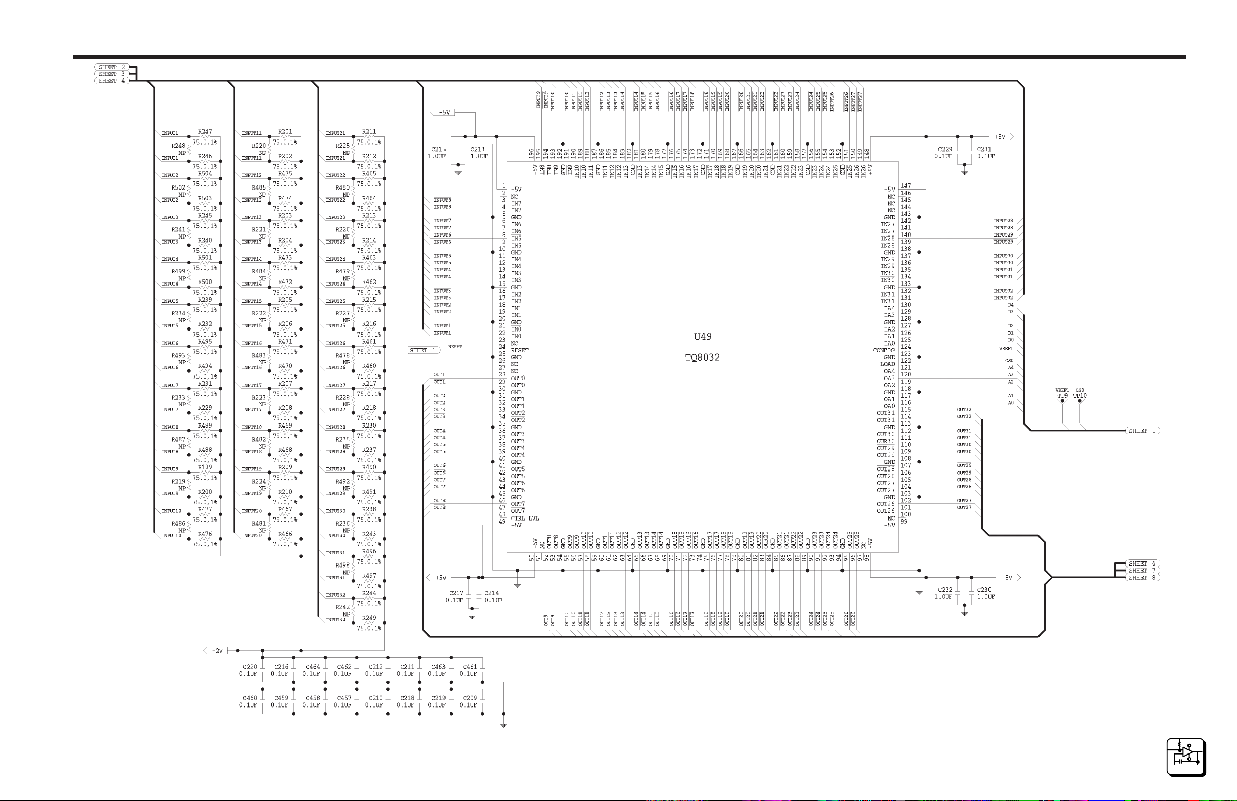
Digital Video
Schematics Section 6
4/98
P/N 81905903440
Schematic (Sheet 5 of 9) • 32X32 Digital Video Matrix Card • SC33-1278
page 6.14
6
SCHEM ATI CS
Page 51

Digital Video
Schematics Section 6
4/98
P/N 81905903440
Schematic (Sheet 6 of 9) • 32X32 Digital Video Matrix Card • SC33-1278
page 6.15
6
SCHEM ATI CS
Page 52
Digital Video
Schematics Section 6
4/98
P/N 81905903440
Schematic (Sheet 7 of 9) • 32X32 Digital Video Matrix Card • SC33-1278
page 6.16
6
SCHEM ATI CS
Page 53
Digital Video
Schematics Section 6
4/98
P/N 81905903440
Schematic (Sheet 8 of 9) • 32X32 Digital Video Matrix Card • SC33-1278
page 6.17
6
SCHEM ATI CS
Page 54
Digital Video
Schematics Section 6
4/98
P/N 81905903440
Schematic (Sheet 9 of 9) • 32X32 Digital Video Matrix Card • SC33-1278
page 6.18
6
SCHEM ATI CS
Page 55
Digital Video
Schematics Section 6
4/98
P/N 81905903440
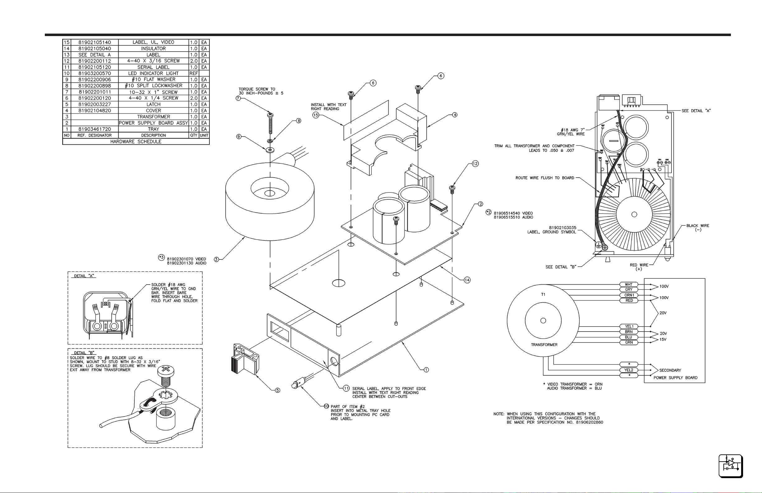
Configuration Drawing • Power Supply Assembly • CD63-0683
page 6.19
6
SCHEM ATI CS
Page 56
Digital Video
Schematics Section 6
4/98
P/N 81905903440
Component Assembly • Power Supply Card • CA25-1162
page 6.20
6
SCHEM ATI CS
Page 57
Digital Video
Schematics Section 6
4/98
P/N 81905903440
Schematic • Power Supply Card • SC33-1162
page 6.21
6
SCHEM ATI CS
Page 58

Digital Video
7.1 Parts List
General
The Parts List in this section have been grouped according to each assembly associated with the Cougar Digital Video Routing Switcher. Refer to
each list by name of card, board, or section of the equipment requiring
replacement parts.
Part Part Number Page
Cougar Mainframe 81906517410 7.2
Cougar Chassis 81906517510 7.3
32X32 Video Backplane 81906517520 7.4
32X32 Digital Video Matrix Card 81906517480 7.5
Power Supply Assembly 81906514550 7.9
Power Supply Card 81906514540 7.10
Parts List Section 7
4/98
P/N 81905903440
page 7.1
7
PARTS LISTS
Page 59

Digital Video
Section 7Parts List
Cougar Mainframe - 81906517410
81901701730 FAN 12V 10.8cfm 40x28mm 2 EA
81901702700 AIR FILTER 7" x 4.5" 1 EA
81902003227 LATCH SLIDE BLK TAB CEI 2 EA
81902200146 SCREW 4-40x3/8 PN HD PHIL 3 EA
81902200237 SCREW 4-40x1.25 PN HD PHI 8 EA REF:FAN
81902202647 SCREW 4-40x1/4 SIMM PANHD 4 EA
81902202980 #6 WING NUT 2 EA REF:AIR FILTER
81902202990 SCREW 8-32x1/2 WING HEAD 3 EA REF: P.S. SHIPPING SCREWS
81902908110 CONN 3 PIN F STRAIN RELF 10 EA REF: FANS, ALARMS, CPU
81903463810 DOOR 32x32 CHASSIS 1 EA
81903463820 VID REAR PLATE 32x32 CHAS 1 EA
81903463890 CPU SHIPPING SUPT 32x32 1 EA
81906517510 CHASSIS 32x32 1 EA
81906517520 32x32 VIDEO BACKPLANE 1 EA
CD63-0758 DOC MAINFRAME 32x32 0 EA
7
PARTS LISTS
page 7.2
4/98
P/N 81905903440
Page 60

Digital Video
Parts List Section 7
Cougar Chassis - 81906517510
81902105220 CARD GUIDE PLASTIC 3" 6 EA
81902201409 SCREW 4-40x1/4 FLT HD PHI 6 EA
81902202647 SCREW 4-40x1/4 SIMM PANHD 3 EA
81903463790 TRAY 32x32 CHASSIS 1 EA
81903463870 COVER TOP CHASSIS 32x32 1 E A
CD63-0759 DOC CHASSIS 32x32 0 EA
4/98
P/N 81905903440
page 7.3
7
PARTS LISTS
Page 61

Digital Video
Section 7Parts List
32X32 Video Backplane - 81906517520
81900700774 CAP 1MF 50V CERAMIC RADIL 32 EA C1-C32
81902003530 PIN GUIDE VIDEO MATRIX 1 EA
81902105050 LABEL BARCODE 1.5"x0.25" 1 EA
81902200070 NUT 4-40 HEX 1 EA
81902202696 SCREW 4-40x7/16 SIMM PANH 6 EA REF J13-J15
81902412810 PCB 32x32 VID BACKPLANE 1 EA
81902600436 SWITCH 8 POS DIP 16-PIN 3 EA S1 S2 S3
81902903061 CONN 6-POS MNL FEMALE RED 1 EA J1 8
81902906486 CONN BNC PRESS-IN 75 OHM 68 EA J25-J92
81902906908 CONN 96-PIN MALE PRESS-IN 6 EA J1 J2 J5 J6 J7 J8
81902906932 CONN 9-PIN MALE D SOLDER 3 EA J13 J14 J15
81902907200 CONN 16-POS PC MT FEMALE 2 E A J21 J22
81902907980 CONN 2x12 PST PRESS .1x.1 8 EA J3 J4
81902908010 CONN 5 PIN 5.08mm VT MALE 1 EA J9 3
81902908100 CONN 3 PIN PC MNT VERTCL 10 EA J9 J10 J11 J12 J16 J17 J23 J24 J19
J20
CA25-1281 DOC 32x32 VIDEO BCKPLNE 0 E A
NOT-PLD ITEMS NOT PLACED ON EBOM 0 E A R1-R64
SC33-1281 DOC 32x32 VIDEO BCKPLNE 0 E A
7
PARTS LISTS
page 7.4
4/98
P/N 81905903440
Page 62

Digital Video
Parts List Section 7
32X32 Digital Video Matrix Card - 81906517480
81900601022 THERMISTOR 680 OHM 5% 2 EA R832 R934
81901000740 CAP SWXR REG OUT 35V ELEC 3 E A C260 C273 C278
81901000760 CAP SWXR REG OUT 10V 12mm 5 EA C259 C257 C274 C481 C482
81901000840 CAP 0.1F 5.5V 1 EA C242
81901000850 CAP DA SWX REG 35V ELECT 2 E A C926 C952
81901500827 DIODE PACK MBR2045 1 EA U74
81901601187 REG MC7805C +5V 1A TO-220 1 EA U72
81901603738 REG LM317T 1.2V-37V ADJST 2 E A U76 U77
81901606830 IC 7.3728 MHZ OSCILLATOR 1 E A XTAL1
81901606980 REG LT1170 5A SWXING 60V 1 E A U73
81901607070 IC LT1172CN8 60V 1A 8PDIP 1 E A U75
81901900270 HEATSINK WITH 12V FAN 1 EA REF:U49
81901900280 HEATSINK LOW PROFILE 1 EA REF:U74
81901900290 HEATSINK TO-3 4 PIN 1 EA REF:U73
81902104512 INSERT/EXTRACTR NYLON 2 EA REF:SHIELD PLATE
81902105050 LABEL BARCODE 1.5"x0.25" 1 EA
81902200070 NUT 4-40 HEX 4 EA REF:U73 U74
81902202647 SCREW 4-40x1/4 SIMM PANHD 4 EA REF:SHIELD PLATE
81902202704 SCREW 4-40x3/8 PN HD SIMM 4 EA REF:U73 U74
81902301080 INDUCTOR 20uH 2A TOROIDAL 3 EA L18 L19 L22
81902301280 TRANSFORMER CUST SDV24x16 1 EA T1
81902301300 TRANSFORMER SDVDA3001 1 EA T2
81902301330 INDUCTOR 30 UH CUSTOM 1 EA L20
81902412780 PCB 32x32 VID DIGTL MATRX 1 EA
81902700880 FUSE 5A PICO AXIAL 125V 2 EA F1 F2
81902903160 HEADER 2 PIN MTA LOCKING 1 EA J5
81902905934 CONN 2-PIN MTA-100 24AWG 1 E A REF:FAN
81902906668 CONN RA,FEMALE,96POS,3ROW 2 EA J1 J2
81902908000 CONN 2x48 RECPT RA .1x.1 2 EA J2 J3
81902908060 SPLIT TERMINAL 4 EA REF:F1 F2
81903200541 LED GREEN RT/A HI-EFF PCB 1 EA C R7
81903200558 LED RED RT/A HI-EFF PC MT 2 EA CR5 CR6
81903463860 MATRIX BD SHIELD 32x32 1 EA
81903900700 INDUCT 20MH 1A TORIODAL 2 E A L17 L21
81906517980 SOFT COUGAR BIOS 1 EA REF:U56
81906600424 RESISTOR 100 OHM 5% 0805 1 EA R254
81906600465 RESISTOR 150 OHM 5% 0805 33 EA R52 R54 R56 R58 R60 R62 R64
R66 R68 R70 R72 R74 R76 R78
R80 R82 R152 R154 R156 R158
R160 R162 R164 R166 R168 R170
R172 R174 R176 R178 R180 R182
R274
81906600549 RESISTOR 330 OHM 5% 0805 12 EA R49 R50 R260 R279 R287 R292
R293 R294 R298 R299 R568 R575
81906600663 RESISTOR 1K OHM 5% 0805 8 EA R149 R150 R295 R569 R570 R571
R572 R573 R574
81906600700 RESISTOR 1.5K 5% 0805 2 EA R265 R288
4/98
P/N 81905903440
page 7.5
7
PARTS LISTS
Page 63

Digital Video
Section 7Parts List
32X32 Digital Video Matrix Card - 81906517480 Continued:
81906600747 RESISTOR 2.2K 5% 0805 32 EA R115-R130 R380-R395
81906600783 RESISTOR 3.3K 5% 0805 SMT 1 EA R253
81906600820 RESISTOR 4.7K 5% 0805 SMT 36 EA R250 R252 R256 R258 R264 R271
R505-R534
81906600945 RESISTOR 15K 5% 0805 SMT 1 E A R257
81906600986 RESISTOR 22K 5% 0805 SMT 1 E A R251
81906601133 RESISTOR 100K 5% 0805 SMT 4 EA R147 R148 R255 R259
81906601307 RESISTOR 510K 5% 0805 SMT 2 E A R278 R286
81906601372 RESISTOR 1M 5% 0805 SMT 1 EA R281
81906610399 RESISTOR 24.9 OHM 1% 0805 32 EA R536-R567
81906610680 RESISTOR 49.9 OHM 1% 0805 64 EA R396-R459
81906610852 RESISTOR 75.0 OHM 1% 0805 64 EA R199-R218 R229-R232 R237-R240
R243-R247 R249 R460-R477
R488-R491 R494-R497 R500 R501
R503 R504
81906610880 RESISTOR 80.6 OHM 1% 0805 1 EA R297
81906611930 RESISTOR 1.0K 1% 0805 SMT 5 EA R261 R266 R289 R290 R291
81906612264 RESISTOR 2.21K 1% 0805 2 EA R267 R283
81906612296 RESISTOR 2.37K 1% 0805 1 EA R269
81906612320 RESISTOR 2.55K 1% 0805 3 EA R268 R270 R277
81906612340 RESISTOR 2.67K 1% 0805 2 EA R282 R285
81906612460 RESISTOR 3.57K 1% 0805 3 EA R272 R273 R284
81906612500 RESISTOR 4.02K 1% 0805 1 EA R262
81906612593 RESISTOR 4.99K 1% 0805 2 EA R263 R275
81906612882 RESISTOR 10K 1% 0805 SMT 1 E A R276
81906621513 RESISTOR 1 OHM 5% 1206 2 E A R280 R296
81906630810 RESISTOR 68.1 OHM 1% 1206 16 E A R18 R20 R22 R24 R26 R28 R30
R32 R34 R36 R38 R40 R42 R44
R46 R48
81906630830 RESISTOR 71.5 OHM 1% 1206 16 EA R317 R319 R321 R323 R325 R327
R329 R331 R333 R335 R337 R339
R341 R343 R345 R347
81906640024 RESISTOR 2.0 OHM 5% 1210 1 EA R535
81906640073 RESISTOR 75 OHM 0.5% 1206 32 EA R1-R16 R300-R315
81906700067 CAP SMT 4.7pf 50V 0805 16 EA C314 C316 C318 C320 C322 C324
C326 C328 C330 C332 C334 C336
C338 C340 C342 C344
81906700208 CAP 47PF 50V CERAMIC 0805 32 EA C1 C3 C5 C7 C9 C11 C13 C15 C17
C19 C21 C23 C25 C27 C29 C31
C281 C283 C285 C287 C289 C291
C293 C295 C297 C299 C301 C303
C305 C307 C309 C311
81906700320 CAP 220PF NPO 0805 CERAMC 2 E A C236 C237
81906700390 CAP 1.2PF 50V NPO 0805 16 EA C34 C36 C38 C40 C42 C44 C46
C48 C50 C52 C54 C56 C58 C60
C62 C64
81906710110 CAP 0.15MF 50V CERAM 1206 2 EA C250 C264
7
PARTS LISTS
page 7.6
4/98
P/N 81905903440
Page 64

Digital Video
Parts List Section 7
32X32 Digital Video Matrix Card - 81906517480 Continued:
81906730015 CAP 0.1MF 50V CERMIC 1206 209 EA C65-C80 C129-C160 C193-C212
C214 C216-C225 C227-C229 C231
C233 C234 C235 C238-C241 C244
C246 C247 C248 C252 C254 C255
C258 C261 C262 C265 C270 C275
C279 C345-C360 C377-C464 C483
81906730056 CAP 0.01MF 50V CERAM 1206 1 EA C251
81906760160 CAP 1500PF 50V CERAM 1206 2 EA C256 C263
81906760220 CAP 1.0MF 50V CERMAM 1825 4 EA C213 C215 C230 C232
81906770037 CAP TANTLM,SMT,2.2MFD/35V 9 EA C266-C269 C271 C272 C276 C277
C280
81906770052 CAP 1MF 20V TANLUM SIZE A 34 EA C82 C84 C86 C88 C90 C92 C94
C96 C98 C100 C102 C104 C106
C108 C110 C112 C162 C164 C166
C168 C170 C172 C174 C176 C178
C180 C182 C184 C186 C188 C190
C192 C245 C249
81906770060 CAP 10MF 6.3V TANT CASE B 35 E A C2 C4 C6 C8 C10 C12 C14 C16
C18 C20 C22 C24 C26 C28 C30
C32 C226 C243 C253 C282 C284
C286 C288 C290 C292 C294 C296
C298 C300 C302 C304 C306 C308
C310 C312
81906800016 TRANS SMT,MMBT3904LT1 1 EA Q 3
81906800065 TRANS SMT,MMBZ5234B 1 EA CR 1
81906800107 TRANS SMT,MMBT3906L 5 EA Q1 Q2 Q4 Q5 Q6
81906800230 DIODE MBR340 40V 3A SHTTK 4 E A CR10 CR11 CR13 CR8
81906800360 ZENER MB5244 14V SOT-23 3 EA CR2 CR3 CR4
81906800390 ZENER MC15 15V 1.5W SMT 1 EA CR12
81906800410 TRANSIENT SUPPRESSOR 33V 2 EA CR9 CR14
81906810072 IC 3903 QUAD SPLY MONITOR 1 EA U95
81906810106 IC LM1881 VID SYNC SEPART 2 E A U69 U71
81906810171 IC SMT,74HC04 (SOIC-14) 1 EA U62
81906810340 IC 74HC00 QUAD AND SO SMT 2 EA U60 U61
81906810410 IC GS9004 CABEL EQUALIZER 32 E A U1-U16 U78-U93
81906810430 IC GS9007 DIGITL CABL DRV 32 EA U17-U48
81906810510 IC 6264 8Kx8 SRAM 100ns 1 E A U 58
81906810550 IC 74HC245 OCTL TRANSCEVR 5 EA U50-U53 U96
81906810570 IC 74HC373 OCTAL LATCH SO 1 E A U54
81906810690 IC TL062 DUAL JFET OP S08 2 EA U66 U70
81906810790 IC TQ8032 32x32 XPT DIGTL 1 E A U49
81906810890 IC RS485 RECVR/TRANSMITTR 1 E A U63
81906810930 IC TL7705 MICRO SUPERVISR 1 EA U64
81906810960 IC OPTOCOUPLER SMT 4N32 2 E A U67 U68
81906811030 IC 74HC273 OACTAL REGISTR 1 EA U55
81906811040 IC 74HC138 3 TO 8 DECODER 2 EA U59 U65
81906811080 IC DS1210 NONVOL CNTL CHP 1 E A U57
4/98
P/N 81905903440
page 7.7
7
PARTS LISTS
Page 65

Digital Video
Section 7Parts List
32X32 Digital Video Matrix Card - 81906517480 Continued:
81906920030 SWITCH DIP 4 POS GULLWING 1 E A S1
81906940040 SOCKET 52 PIN PLCC SMT 1 EA REF:U56
81906950019 INDUCT SMT, .010UH 32 EA L1-L16 L23-L38
81906950040 BEAD INDUCTOR SMT 2 EA B1 B2
CA25-1278 DOC 32x32 VID DIGTL MATRX 0 E A
NOT-PLD ITEMS NOT PLACED ON EBOM 0 EA R51 R53 R55 R57 R59 R61 R63
R65 R67 R69 R71 R73 R75 R77
R79 R81 R83-R114 R151 R153
R155 R157 R159 R161 R163 R165
R167 R169 R171 R173 R175 R177
R179 R181 R219-R228 R233-R236
R241 R242 R248 R348-R379
R478-R487 R492 R493 R498 R499
R502 C33 C35 C37 C39 C41 C43
C45 C47 C49 C51 C53 C55 C57
C59 C61 C63 C113-C128 C313
C315 C317 C319 C321 C323 C325
C327 C329 C331 C333 C335 C337
C339 C341 C343 C361-C376 C465C471 C473-C480 R17 R19 R21 R23
R25 R27 R29 R31 R33 R35 R37
R39 R41 R43 R45 R47 R316 R318
R320 R322 R324 R326 R328 R330
R332 R334 R336 R338 R340 R342
R344 R346 C81 C83 C85 C87 C89
C91 C93 C95 C97 C99 C101 C103
C105 C107 C109 C111 C161 C163
C165 C167 C169 C171 C173 C175
C177 C179 C181 C183 C185 C187
C189 C191 R131-R146 R183-R198
TP1-TP10
SC33-1278 DOC 32x32 VID DIGTL MATRX 0 E A
7
PARTS LISTS
page 7.8
4/98
P/N 81905903440
Page 66

Digital Video
Parts List Section 7
Power Supply Assembly - 81906514550
81902003227 LATCH SLIDE BLK TAB CEI 1 EA
81902103035 LABEL GROUND SYMBOL 1 EA
81902104820 COVER AC DA3000 PLASTIC 1 EA
81902105040 INSULATOR PS70 CARD/TRAY 1 EA
81902105120 LABEL 2"x1" METAL POLYEST 1 EA
81902105140 LABEL CAUTION PS70V U.L. 1 EA
81902200112 SCREW 4-40x3/16 PN HD PHI 2 EA
81902200120 SCREW 4-40x1/4 PN HD PHIL 2 EA
81902200674 SCREW 8-32x3/16 PH SS PHI 1 E A
81902200898 WASHER #10 SPLIT LOCK 1 EA
81902200906 WASHER #10 FLAT 1 EA
81902201011 SCREW 10-32 x 1" PN HD PH 1 EA
81902301070 TRANSFORMER VID PS70 TORO 1 EA
81902700820 FUSE 1.25A SLOBLO 5x20mm 2 EA
81902804030 CORD PWR 3 CND 18AWG 7’6" 1 EA
81902804040 WIRE 18 AWG GRN/YEL 7 IN
81902907590 FUSE DRAWER 2 POLE PC MNT 1 EA
81902908080 LOCKWASHER TERM LUG #8 1 EA
81903461720 TRAY PS70 PWR SUPPLY BD 1 E A
81906514540 PS70 VIDEO BOARD ASSEMBLY 1 EA
CD63-0683 DOC PWR SUPPLY PS70 A/V 0 E A
4/98
P/N 81905903440
page 7.9
7
PARTS LISTS
Page 67

Digital Video
Power Supply Card - 81906514540
81900200601 RESISTOR 560 OHM 5% 1/4W 3 E A R1 R6 R7
81900200684 RESISTOR 1.2K 5% 1/4W 1 EA R3
81900200767 RESISTOR 2.7K 5% 1/4W 1 EA R 5
81900201179 RESISTOR 150K 5% 1/4W 1 EA R 2
81900201294 RESISTOR 470K 5% 1/4W 1 EA R 4
81900601022 THERMISTOR 680 OHM 5% 1 EA R8
81900700055 CAP 0.1MF 50V CERAM RADIL 1 EA C 5
81900900168 CAP 1MF 50V TANTLM AXIAL 2 E A C3 C4
81901000800 CAP C1 & C2 PS70 VIDEO 2 EA C1 C2
81901400465 TRANS MPSA77 PNP TO-92 2 EA Q1 Q2
81901500173 ZENER 1N5244 14V 9MA 2 EA D13 D12
81901500587 DIODE 1N4001 3 EA D9 D10 D11
81901500910 DIODE MBR745 SCHKY TO-220 8 EA D1-D8
81901602318 IC 4N33 OPTO DARLNGTN OUT 2 E A U1 U2
81901606244 REG LM317MT POS .5A TO220 1 E A V R1
81901900250 HEATSINK AAVID 574004B 1 EA
81902411620 PCB PWR SUPPL BD PS70 A/V 1 EA
81902600890 SWITCH 6-POS 3A AC SELECT 1 EA SW1
81902800507 WIRE 22AWG BUSS 1 IN
81902903350 JUMPER 2 POSITION 1 EA
81902903483 HEADER 3 POS 1 EA J 1
81902907190 CONN AC W/FUSE PC MT 10A 1 EA P1
81902907210 CONN 16-PIN HEADER R/A MA 1 EA P2
81903200558 LED RED RT/A HI-EFF PC MT 1 EA CR 2
81903200570 LED GREEN PNL MT w/LEADS 1 EA CR1
PK65-1454 DOC PWER SUPPLY BD DA3000 0 EA
Section 7Parts List
7
PARTS LISTS
page 7.10
4/98
P/N 81905903440
Page 68

Internal PS130 Power Supply Addendum
Introduction
*CAUTION*
PS130 POWER SUPPLIES CONTAIN ELECTRICAL SHOCK HAZARDS AND SHOULD
ONLY BE SERVICED BY QUALIFIED SERVICE PERSONNEL WITH EXPERIENCE IN
SERVICING OFF-LINE SWITCHING REGULATORS.
*CAUTION*
There are no user serviceable parts contained in the PS130 Power Supply. All service
performed on the PS130 Power Supply should be accomplished by qualified service personnel. The internal circuits of the PS130 Power Supply contain dangerous voltage
and current levels. Prior to servicing any PS130 Power Supply make absolutely sure
that the AC line input is disconnected.
*NOTE*
The PS130 Power Supply replaces the power supply formerly used to power the PESA
equipment item referenced in the technical manual to which this addendum is attached.
This addendum takes precedence over any mention of the former power supply in the
technical manual for any PESA equipment items where the PS130 Power Supply is utilized.
This addendum contains the power connection, front door removal and
replacement, power supply removal and installation, and fuse replacement
instructions for the PS130 Power Supply. The purpose of this addendum
is to provide technical information to the customer concerning the operation and servicing of the PS130 Power Supply.
General
*CAUTION*
HIGH LEAKAGE CURRENT AT 230 VAC
The PS130 Power Supply leakage current exceeds 3.5mA when used at 230VAC because
of leakage through emission filter capacitors.
3/98
Internal PS130 Power Supply Addendum page 1
Page 69

Internal PS130 Power Supply Addendum
The PS130 Video Power Supply is responsible for providing a regulated
±8.9VDC @ 5.5A to the switching frame. The PS130 Power Supply is
designed to operate within output specifications with AC line voltages
ranges from 105 - 240 VAC and with AC line frequencies of 50/60 Hz
automatically. 3.15A 250VAC AC line fuses provide over-load protection.
The PS130 Audio Power Supply is responsible for providing a regulated
±24VDC @ 2.35A to the switching frame. The PS130 Power Supply is
designed to operate within output specifications with AC line voltages
ranges from 105 - 240 VAC and with AC line frequencies of 50/60 Hz
automatically. 3.15A 250VAC AC line fuses provide over-load protection.
*CAUTION*
Disconnect AC Power Cord Before Removing Power Supply.
In the event of a PS130 Power Supply failure, PESA suggets returning
the malfunctioning unit to the PESA Service Department for replacement.
PS130 Power Supplies contain lethal voltages when operating and
should only be serviced by technicians qualified to service off-line
switching regulators. Please call the PESA Service Department for a
RMA number before returning any units for replacement. The service
department's phone number is listed on the Service and Ordering Assistance Page.
Power Connections
*CAUTION*
PS130 POWER SUPPLIES CONTAIN ELECTRICAL SHOCK HAZARDS AND SHOULD
ONLY BE SERVICED BY QUALIFIED SERVICE PERSONNEL AND/OR QUALIFIED
TECHNICIANS.
*CAUTION*
THIS POWER SUPPLY USES AN INDIVIDUAL AC POWER CORD.
DISCONNECT CORD BEFORE REMOVING SUPPLY.
Internal PS130 Power Supply Addendumpage 2
3/98
Page 70

Internal PS130 Power Supply Addendum
Power Connect
To power-up a PS130 Power Supply and its associated routing switcher
frame take the following steps:
1. Insert the power supply into the frame following the instructions in the
Power Removal Section of this addendum.
2. Connect the power supply to the AC line.
3. Repeat steps 1 and 2 for a secondary power supply if applicable.
4. If applicable, connect any DC power looped to and from other frames
in the routing switcher system to the unit under test.
Power Disconnect
To power-down a PS130 Power Supply, disconnect the AC power
cord from the power supply's AC line input connector. To power-down
a PS130 Power Supply and its associated routing switcher frame take the
following steps:
1. If applicable, disconnect any DC power looped to and from other
frames in the routing switcher system from the unit under test.
2. Disconnect the AC line from the primary PS130 Power Supply.
3. If applicable, disconnect the AC line from the secondary PS130 Power
Supply.
Front Door Removal and Replacement
Front Door Removal (Removable Front Doors Only)
To remove the PESA equipment item's front door (cover) take the following steps:
1. Grasp the both the left and right front cover slide locks and push or pull
them towards the center of the equipment item's front.
2. Once both slide locks are slide toward the center of the equipment
items front, carefully pull the front door off the equipment item.
3/98
Internal PS130 Power Supply Addendum page 3
Page 71

Internal PS130 Power Supply Addendum
Front Door Installation (Removable Front Doors Only)
To install the PESA equipment item's front door (cover) take the following
steps:
1. Align the front door with the front of the PESA equipment item.
2. Once the front door is aligned with the front of the PESA equipment
item, slide the front door onto the equipment item until the slide locks
snap into the locking provided on the equipment item's chassis.
Power Supply Removal and Replacement
*CAUTION*
Two AC Power Cords may be connected to this unit.
Power Supply Removal
To remove the PESA equipment item's power supply or power supplies take the
following steps:
1. Disconnect the AC power cord connected to the power supply to be
removed.
2. Remove or open the equipment item's front door.
3. Grasp the power supply slide lock and pull it toward the center of the supply.
4. Once the slide lock is slid toward the center of the supply, carefully pull the
power supply out of the equipment chassis.
5. Repeat step 1 and steps 3 and 4 to remove any additional power supplies
from the equipment item.
Power Supply Installation
To install the PESA equipment item's power supply or power supplies take the
following steps:
1. Align the primary power supply with the primary set of power supply circuit
card guides in the equipment item's chassis.
Internal PS130 Power Supply Addendumpage 4
3/98
Page 72

Internal PS130 Power Supply Addendum
2. Carefully push the power supply into the chassis until the power supply
connector makes initial contact with the backplane power connector. At this
point, firmly but carefully continue pushing the power supply into the equipment chassis while making sure the power connectors are properly aligned.
You may have to slide the power supply latch toward the center of the supply
in order for the latch to move past the frame's metal work. Continue pushing
the power supply until the power supply slide lock clicks into the power supply
slide lock hole provided in the equipment chassis and the power connectors
are firmly mated.
3. If additional power supplies are to be installed in the equipment chassis, align
them with a set of power supply circuit card guides in the equipment item and
repeat step 2.
Fuse Replacement
*CAUTION*
DOUBLE-POLE/NEUTRAL FUSING
To replace the PS13O Power Supply line fuses take the following steps:
1. Disconnect the AC power cord from the power supply being ser-
viced.
2. Remove or open the front door of the equipment item containing the
PS130 Power Supply needing serviced.
3. Remove the power supply from the equipment item. Refer to the
Power Supply Removal Section of this addendum for power supply
removal instructions.
4. Carefully pull the AC line fuse holder open. The fuse holder is located
adjacent to the PS130 Power Supply AC line input connector.
5. Replace the fuses with fuses of equal current and voltage rating.
6. Carefully slide the AC line fuse holder closed.
7. Install the power supply back into the equipment chassis. Refer to the
Power Supply Installation Section of this addendum for complete
power supply installation instructions.
5. Reconnect the associated AC power cord.
3/98
Internal PS130 Power Supply Addendum page 5
Page 73
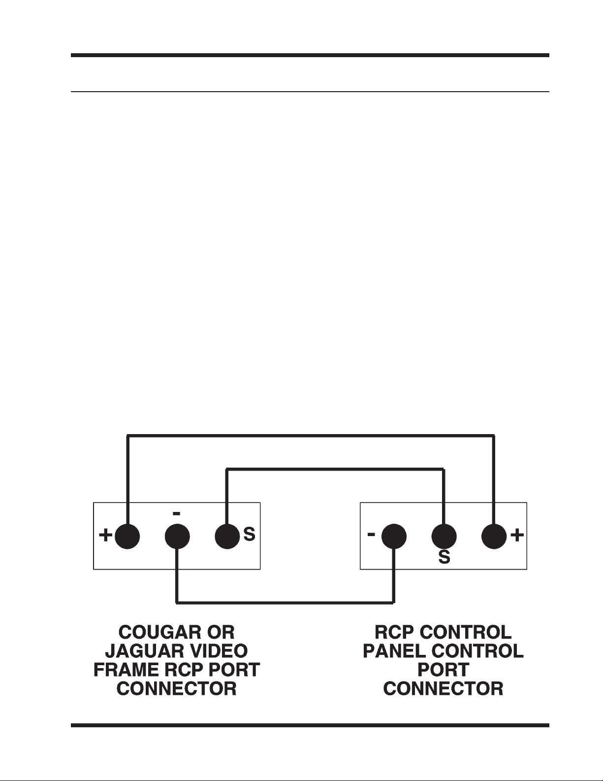
Cougar Video Frame Panel Connection
Cougar Video Frame RCP Port Addendum
This addendum is designed to be utilized as quick reference guide to the
system interconnection between the Cougar Video Frame and the RCP
Control Panels.
The pinout for the RCP Port Connectors on the rear panel of the Cougar
Video Frame is as follows:
Pin 1 +DATA
Pin 2 -DATA
Pin 3 Shield
The pinout for the Control Port Connector on the rear panel of the RCP
Control Panel is as follows:
Pin 1 -DATA
Pin 2 Shield
Pin 3 +DATA
The twisted-pair cables between the Cougar Video Frame RCP Port
Connectors and the RCP Control Panels must be connected as shown in
Figure 1. Please refer to Figures 2 and 3 also when making control panel
connections to the Cougar Video Frame.
Figure 1 Cougar Video Frame and RCP Control Panel Interconnection
4/98
Cougar Video Frame Control Panel Connection page 1
Page 74
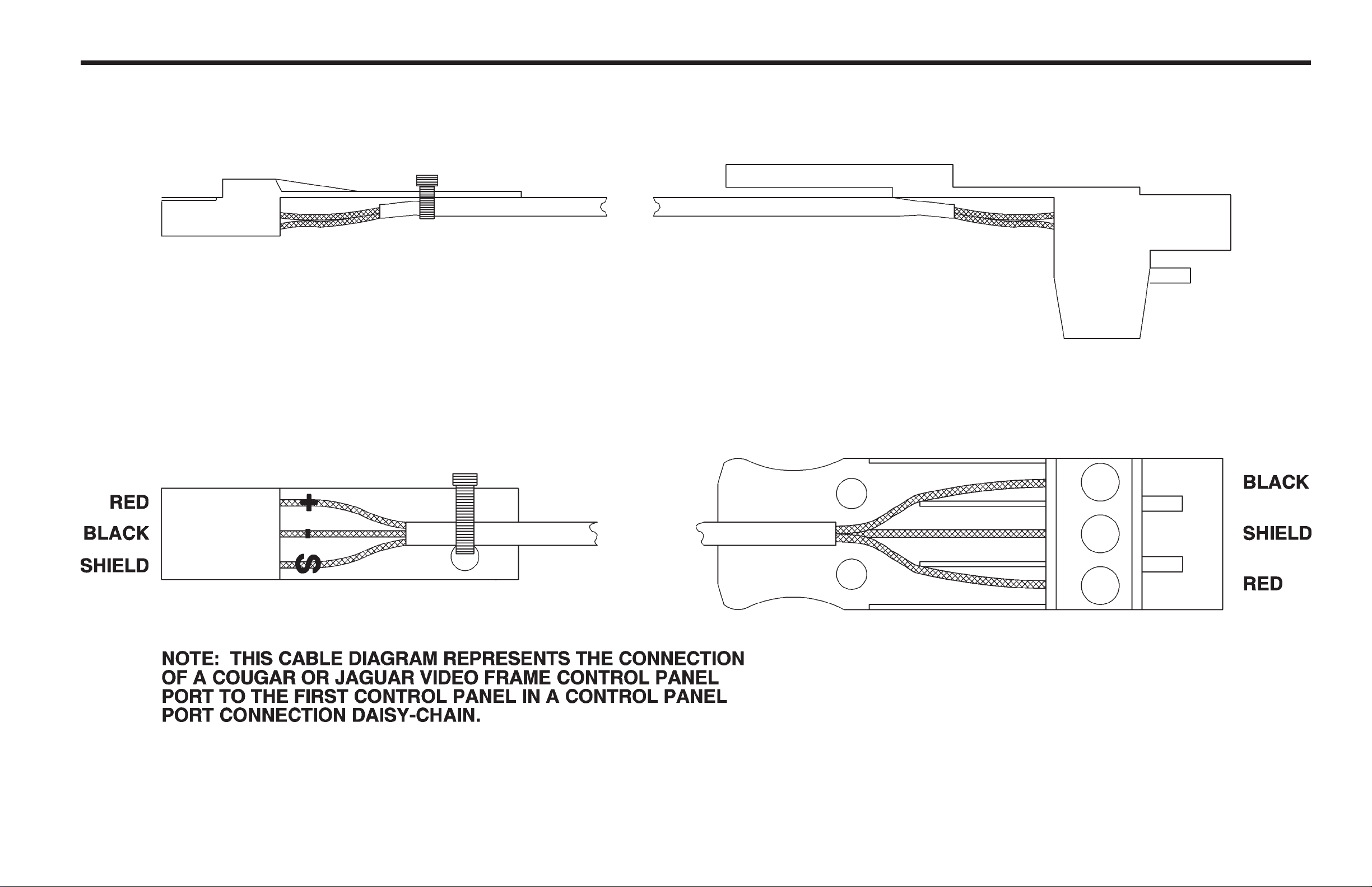
Cougar Video Frame Panel Connection
Figure 2 Cougar or Jaguar Video Frame Control Panel Port to the First Control Panel in a Daisy-Chain Connection
3/98
Cougar Video Frame Control Panel Connection page 2
Page 75
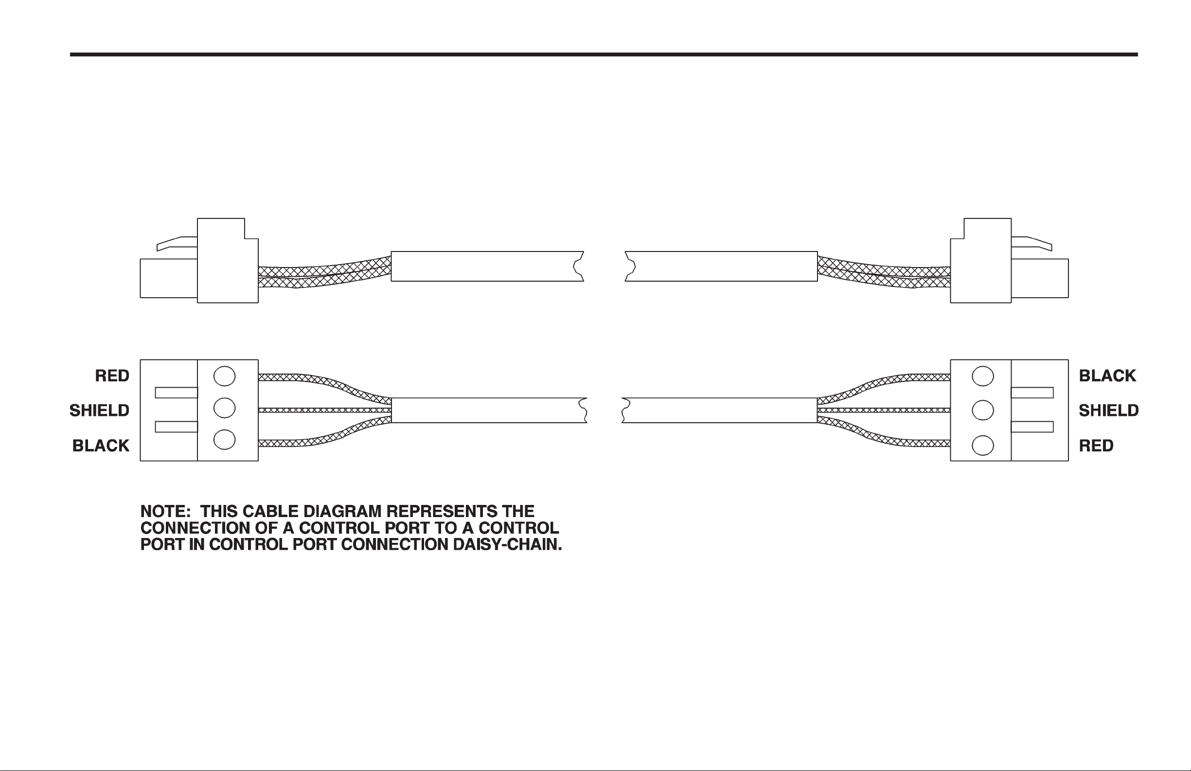
Cougar Video Frame Panel Connection
Figure 3 Control Panel Port to Control Panel Port Connection
3/98
Cougar Video Frame Control Panel Connection page 3
Page 76

32X32 Digital Video Matrix Card Addendum
Introduction
This addendum contains the parts lists and schematics for the latest 32X32
Digital Video Matrix Card. Please refer to this addendum and the Cougar Digital
Video Manual (P/N 81905903440) when troubleshooting or replacing parts on the
updated 32X32 Digital Video Matrix Card.
Parts Lists
The Parts Lists in this section have been grouped according to each assembly
associated with the 32X32 Digital Video Matrix Card. Refer to each list by name
of card, board, or section of the equipment requiring replacement parts.
Part Part Number Page
32X32 Digital Video Matrix Assembly 81906518860 2
32X32 Digital Video Matrix Card 81906518880 3
4/98
32X32 Digital Video Matrix Card Addendum page 1
Page 77

32X32 Digital Video Matrix Card Addendum
32X32 Digital Video Matrix Assembly - 81906518860
81902105050 LABEL BARCODE 1.5"x0.25" 1 EA
81902202647 SCREW 4-40x1/4 SIMM PANHD 5 EA
81903464290 SHIELD VIDEO MATRX JAGUAR 1 EA
81906518880 32X DIGITL VID MTRX BASIC 1 EA
4/98
32X32 Digital Video Matrix Card Addendumpage 2
Page 78

32X32 Digital Video Matrix Card Addendum
32X32 Digital Video Matrix Card - 81906518880
81900601022 THERMISTOR 680 OHM 5% 2 EA R832 R934
81901000720 CAP SWX REG 35V 1.7A RAD 3 EA C312 C334 C340
81901000760 CAP SWXR REG OUT 10V 12mm 5 EA C307-C311
81901000840 CAP 0.1F 5.5V 1 EA C300
81901000850 CAP DA SWX REG 35V ELECT 2 EA C926 C952
81901500827 DIODE PACK MBR2045 1 EA CR21
81901601187 REG MC7805C +5V 1A TO-220 1 EA U73
81901603738 REG LM317T 1.2V-37V ADJST 2 EA U75 U76
81901606830 IC 7.3728 MHZ OSCILLATOR 1 EA XTAL1
81901606980 REG LT1170 5A SWXING 60V 1 EA U96
81901607070 IC LT1172CN8 60V 1A 8PDIP 1 EA U74
81901900270 HEATSINK WITH 12V FAN 1 EA REF U50
81901900280 HEATSINK LOW PROFILE 1 EA REF CR21
81901900290 HEATSINK TO-3 4 PIN 1 EA REF U96
81902105050 LABEL BARCODE 1.5"x0.25" 1 EA
81902200070 NUT 4-40 HEX 4 EA REF CR21 U96
81902202704 SCREW 4-40x3/8 PN HD SIMM 4 EA REF CR21 U96
81902301080 INDUCTOR 20uH 2A TOROIDAL 3 EA L18 L20 L22
81902301280 TRANSFORMER CUST SDV24x16 1 EA T1
81902301300 TRANSFORMER SDVDA3001 1 EA T2
81902301330 INDUCTOR 30 UH CUSTOM 1 EA L19
81902413530 PCB 32X DIGITAL VID MTRX 1 EA
81902700880 FUSE 5A PICO AXIAL 125V 2 EA F1 F2
81902903160 HEADER 2 PIN MTA LOCKING 1 EA J5
81902905934 CONN 2-PIN MTA-100 24AWG 1 EA REF FAN
81902906668 CONN RA,FEMALE,96POS,3ROW 2 EA J3 J4
81902908000 CONN 2x48 RECPT RA .1x.1 2 EA J1 J2
81902908060 SPLIT TERMINAL 4 EA REF F1 F2
81903200541 LED GREEN RT/A HI-EFF PCB 1 EA CR26
81903200558 LED RED RT/A HI-EFF PC MT 2 EA CR24 CR25
81903900700 INDUCT 20MH 1A TORIODAL 2 EA L17 L21
81906517980 SOFT COUGAR BIOS 1 EA U57
81906600424 RESISTOR 100 OHM 5% 0805 3 EA R197 R221 R233
81906600465 RESISTOR 150 OHM 5% 0805 1 EA R214
81906600549 RESISTOR 330 OHM 5% 0805 10 EA R97 R98 R199 R206 R210 R240-
R242 R244 R247
81906600663 RESISTOR 1K OHM 5% 0805 9 EA R117 R118 R135 R166-R170 R237
81906600700 RESISTOR 1.5K 5% 0805 2 EA R211 R231
81906600783 RESISTOR 3.3K 5% 0805 SMT 1 EA R195
81906600820 RESISTOR 4.7K 5% 0805 SMT 39 EA R192 R193 R201 R202 R209 R219
R236 R243 R246 R453-R482
81906600945 RESISTOR 15K 5% 0805 SMT 1 EA R198
81906600986 RESISTOR 22K 5% 0805 SMT 1 EA R194
81906601067 RESISTOR 47K 5% 0805 SMT 1 EA R196
81906601133 RESISTOR 100K 5% 0805 SMT 4 EA R115 R116 R200 R203
81906601307 RESISTOR 510K 5% 0805 SMT 2 EA R220 R230
81906601372 RESISTOR 1M 5% 0805 SMT 2 EA R223 R486
81906610680 RESISTOR 49.9 OHM 1% 0805 64 EA R312-R343 R376-R407
4/98
32X32 Digital Video Matrix Card Addendum page 3
Page 79

32X32 Digital Video Matrix Card Addendum
32X32 Digital Video Matrix Card - 81906518880 Continued:
81906610852 RESISTOR 75.0 OHM 1% 0805 64 EA R136 R138 R139 R141 R142 R144
R145 R147 R148 R150 R151 R153
R154 R156 R157 R159 R160 R162
R163 R165 R171 R172
81906610852 RESISTOR 75.0 OHM 1% 0805 64 EA R175 R176 R177 R178 R181 R182
R183 R184 R187 R188 R189 R190
R408 R410 R411 R413 R414 R416
R417 R419 R420 R422 R423 R425
R426 R428 R429 R431 R432 R434
R435 R437 R438 R439 R440 R441
R445 R446 R447 R450 R451 R452
81906610880 RESISTOR 80.6 OHM 1% 0805 1 EA R239
81906610977 RESISTOR 100 OHM 1% 0805 64 EA R17-R32 R34 R36 R38 R40 R42
R44 R46 R48 R50 R52 R54 R56
R58 R60 R62 R64 R264-R279 R281
R283 R285 R287 R289 R291 R293
R295 R297 R299 R301 R303 R305
R307 R309 R311
81906611300 RESISTOR 221 OHM 1% 0805 33 EA R137 R140 R143 R146 R149 R152
R155 R158 R161 R164 R173 R174
R179 R180 R185 R186 R191 R409
R412 R415 R418 R421 R424 R427
R430 R436 R442 R443 R444 R433
R448 R449 R488
81906611930 RESISTOR 1.0K 1% 0805 SMT 5 EA R204 R205 R234 R235 R238
81906612264 RESISTOR 2.21K 1% 0805 2 EA R212 R232
81906612296 RESISTOR 2.37K 1% 0805 1 EA R216
81906612320 RESISTOR 2.55K 1% 0805 3 EA R215 R217 R218
81906612340 RESISTOR 2.67K 1% 0805 2 EA R227 R229
81906612460 RESISTOR 3.57K 1% 0805 3 EA R213 R222 R228
81906612500 RESISTOR 4.02K 1% 0805 1 EA R207
81906612593 RESISTOR 4.99K 1% 0805 2 EA R208 R224
81906612882 RESISTOR 10K 1% 0805 SMT 1 EA R225
81906621513 RESISTOR 1 OHM 5% 1206 2 EA R226 R245
81906640024 RESISTOR 2.0 OHM 5% 1210 1 EA R483
81906640073 RESISTOR 75 OHM 0.5% 1206 32 EA R1-R16 R248-R263
81906640150 RESISTOR 37.5 OHM 0.5% 08 32 EA R33 R35 R37 R39 R41 R43 R45
R47 R49 R51 R53 R55 R57
81906640150 RESISTOR 37.5 OHM 0.5% 08 32 EA R59 R61 R63 R280 R282 R284
R286 R288 R290 R292 R294 R296
R298 R300 R302 R304 R306 R308
R310
81906640620 RESISTOR 64.9OHM 1% 1206 32 EA R66 R68 R70 R72 R74 R76 R78
R80 R82 R84 R86 R88 R90 R92
R94 R96 R344 R346 R348 R350
R352 R354 R356 R358 R360 R362
R364 R366 R368 R370 R372 R374
4/98
32X32 Digital Video Matrix Card Addendumpage 4
Page 80

32X32 Digital Video Matrix Card Addendum
32X32 Digital Video Matrix Card - 81906518880 Continued:
81906700166 CAP 100PF 50V CERAMC 0805 32 EA C66 C68 C70 C72 C74 C76 C78
C80 C82 C84 C86 C88 C90 C92
C94 C96 C374 C376 C378 C380
C382 C384 C386 C388 C390 C392
C394 C396 C398 C400 C402 C404
81906700320 CAP 220PF NPO 0805 CERAMC 2 EA C293 C294
81906710110 CAP 0.15MF 50V CERAM 1206 2 EA C314 C325
81906730015 CAP 0.1MF 50V CERMIC 1206 259 EA C1-C32 C97-C128 C161-C176
C225-C240 C257-266 C268
C270-C282 C284-C286 C288
C290-C292 C295-C298 C301
C303-C306 C316 C318 C319
C321-C323 C326 C331 C335 C337
C341-C372 C405-C436 C452-C467
C500-C530 C532 C533
81906730056 CAP 0.01MF 50V CERAM 1206 1 EA C315
81906760160 CAP 1500PF 50V CERAM 1206 2 EA C320 C324
81906760220 CAP 1.0MF 50V CERMAM 1825 4 EA C267 C269 C287 C289
81906770037 CAP TANTLM,SMT,2.2MFD/35V 9 EA C327-C330 C332 C333 C336 C338
C339
81906770052 CAP 1MF 20V TANLUM SIZE A 34 EA C130 C132 C134 C136 C138 C140
C142 C144 C146 C148 C150 C152
C154 C156 C158 C160 C194 C196
C198 C200 C202 C204 C206 C208
C210 C212 C214 C216 C218 C220
C222 C224 C302 C313
81906770060 CAP 10MF 6.3V TANT CASE B 3 EA C283 C299 C317
81906800016 TRANS SMT,MMBT3904LT1 4 EA Q3 Q6 Q8 Q9
81906800024 DIODE SMT,MMBD6100,SOT23 32 EA CR1-CR17 CR27-CR41
81906800065 TRANS SMT,MMBZ5234B 2 EA CR19 CR49
81906800107 TRANS SMT,MMBT3906L 5 EA Q1 Q2 Q4 Q5 Q7
81906800230 DIODE MBR340 40V 3A SHTTK 4 EA CR42 CR44 CR45 CR47
81906800360 ZENER MB5244 14V SOT-23 3 EA CR18 CR20 CR23
81906800390 ZENER MC15 15V 1.5W SMT 1 EA CR46
81906800410 TRANSIENT SUPPRESSOR 33V 2 EA CR43 CR48
81906800580 ZENER MBZ5242 12V SOT23 1 EA CR22
81906810072 IC 3903 QUAD SPLY MONITOR 1 EA U95
81906810106 IC LM1881 VID SYNC SEPART 2 EA U68 U72
81906810171 IC SMT,74HC04 (SOIC-14) 1 EA U63
81906810340 IC 74HC00 QUAD AND SO SMT 2 EA U61 U62
81906810510 IC 6264 8Kx8 SRAM 100ns 1 EA U59
81906810550 IC 74HC245 OCTL TRANSCEVR 5 EA U49 U51-U54
81906810570 IC 74HC373 OCTAL LATCH SO 1 EA U55
81906810690 IC TL062 DUAL JFET OP S08 3 EA U67 U71 U97
81906810790 IC TQ8032 32x32 XPT DIGTL 1 EA U50
81906810890 IC RS485 RECVR/TRANSMITTR 1 EA U64
81906810930 IC TL7705 MICRO SUPERVISR 1 EA U65
81906810960 IC OPTOCOUPLER SMT 4N32 2 EA U69 U70
4/98
32X32 Digital Video Matrix Card Addendum page 5
Page 81

32X32 Digital Video Matrix Card Addendum
32X32 Digital Video Matrix Card - 81906518880 Continued:
81906811030 IC 74HC273 OACTAL REGISTR 1 EA U56
81906811040 IC 74HC138 3 TO 8 DECODER 2 EA U60 U66
81906811080 IC DS1210 NONVOL CNTL CHP 1 EA U58
81906811170 IC CLC014 CABLE EQUALIZER 32 EA U1-U16 U77-U92
81906811180 IC CLC006 CABLE DRIVER 32 EA U17-U48
81906920030 SWITCH DIP 4 POS GULLWING 1 EA S1
81906940040 SOCKET 52 PIN PLCC SMT 1 EA REF U57
81906950019 INDUCT SMT, .010UH 32 EA L1-L16 L23-L38
81906950040 BEAD INDUCTOR SMT 2 EA BEAD1 BEAD2
CA25-1353 DOC 32X DIGITAL VID MTRX 0 EA
DD52-1353 DOC 32X DIGITAL VID MTRX 0 EA
NOT-PLACEDITEMS NOT PLACED ON EBOM 0 EA R65 R67 R69 R71 R73 R75 R77
R79 R81 R83 R85 R87 R89 R91
R93 R95 R345 R347 R349 R351
R353 R355 R357 R359 R361 R363
R365 R367 R369 R371 R373 R375
R99-R114 R119-R134 C33 C35 C37
C39 C41 C43 C45 C47 C49 C51
C53 C55 C57 C59 C61 C63 C65
C67 C69 C71 C73 C75 C77 C79
C81 C83 C85 C87 C89 C91 C93
C95 C373 C375 C377 C379 C381
C383 C385 C387 C389 C391 C393
C395 C397 C399 C401 C403 C469
C471 C473 C475 C477 C479 C481
C483 C485 C487 C489 C491 C493
C495 C497 C499 C129 C131 C135
C137 C139 C141 C143 C145 C147
C149 C151 C153 C155 C157 C159
C193 C195 C197 C199 C201 C203
C205 C207 C209 C211 C213 C215
C217 C219 C221 C223 TP1-TP10
C437-C451 C177-C192 C241-C256
C133 C34 C36 C40 C42 C44 C46
C48 C50 C52 C54 C56 C58 C60
C62 C64 C468 C472 C474 C476
C478 C480 C482 C484 C486 C488
C490 C492 C494 C496 C498 C531
C38
SC33-1353 DOC 32X DIGITAL VID MTRX 0 EA
4/98
32X32 Digital Video Matrix Card Addendumpage 6
Page 82

32X32 Digital Video Matrix Card Addendum
Schematics
This section contains the schematic diagrams and parts location diagrams
for the 32X32 Digital Video Matrix Card. Please refer to this section when
troubleshooting the equipment or replacing defective parts.
Description Dwg No. Page No.
32X32 Digital Video Matrix Card CA25-1353 8
SC33-1353 1 0
4/98
32X32 Digital Video Matrix Card Addendum page 7
Page 83
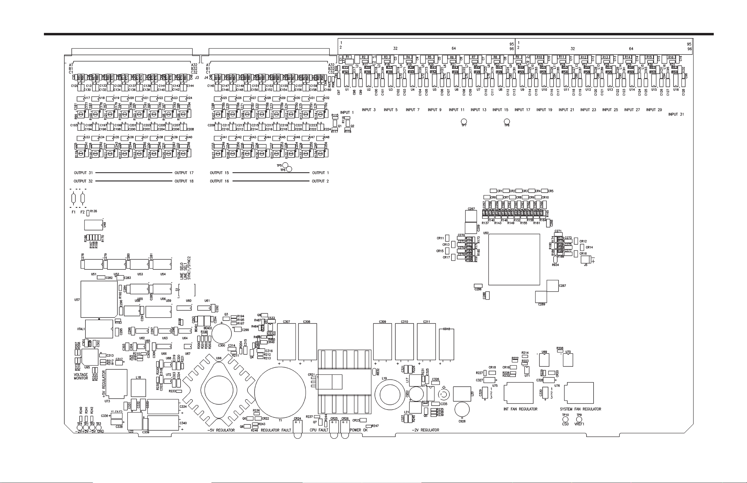
32X32 Digital Video Matrix Card Addendum
Component Assembly (Sheet 1 of 2) • 32X32 Digital Video Matrix Card (REV 02) • CA25-1353
4/98
32X32 Digital Video Matrix Card Addendum page 8
Page 84
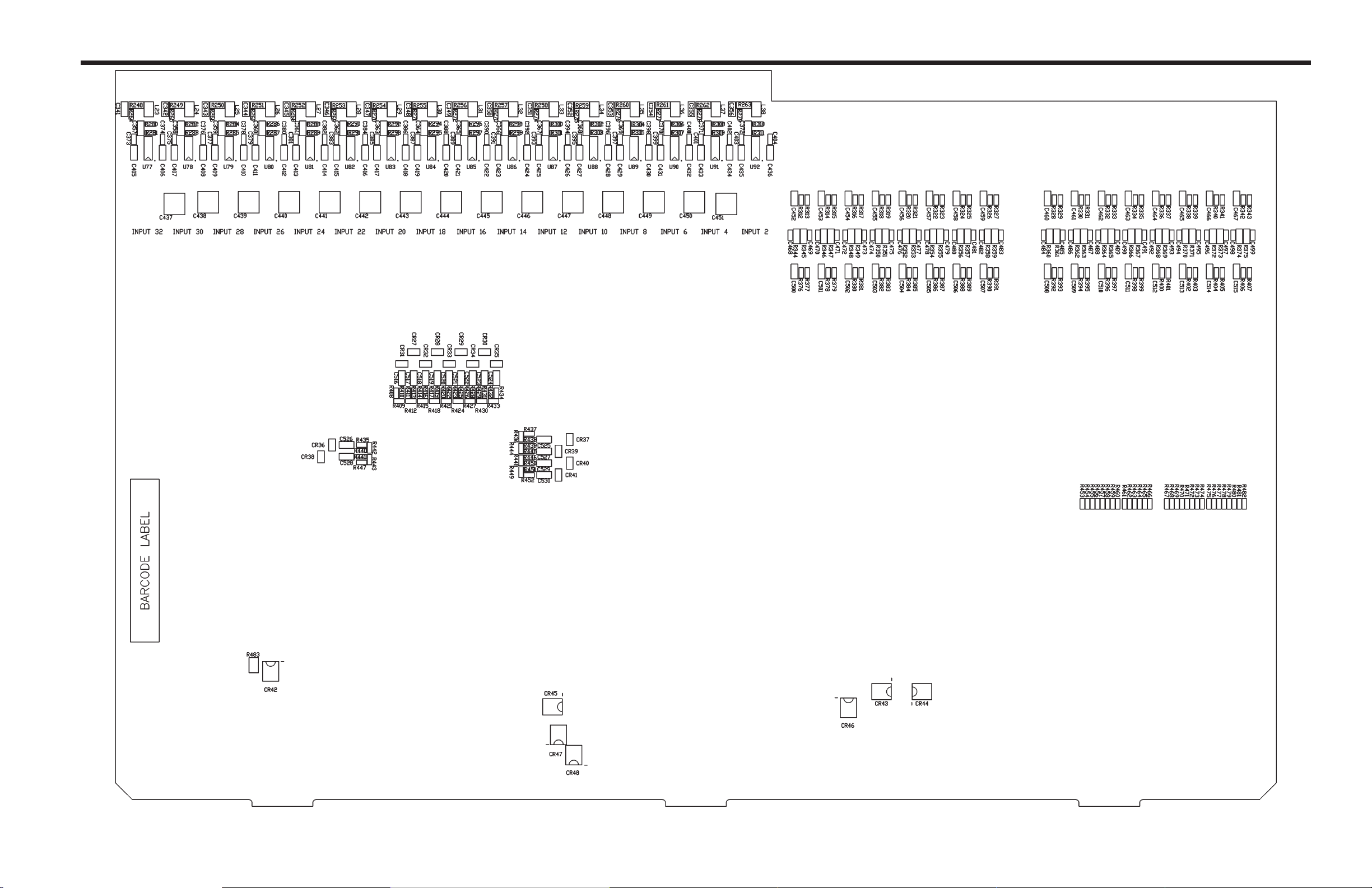
32X32 Digital Video Matrix Card Addendum
Component Assembly (Sheet 2 of 2) • 32X32 Digital Video Matrix Card (REV 02) • CA25-1353
4/98
32X32 Digital Video Matrix Card Addendum page 9
Page 85
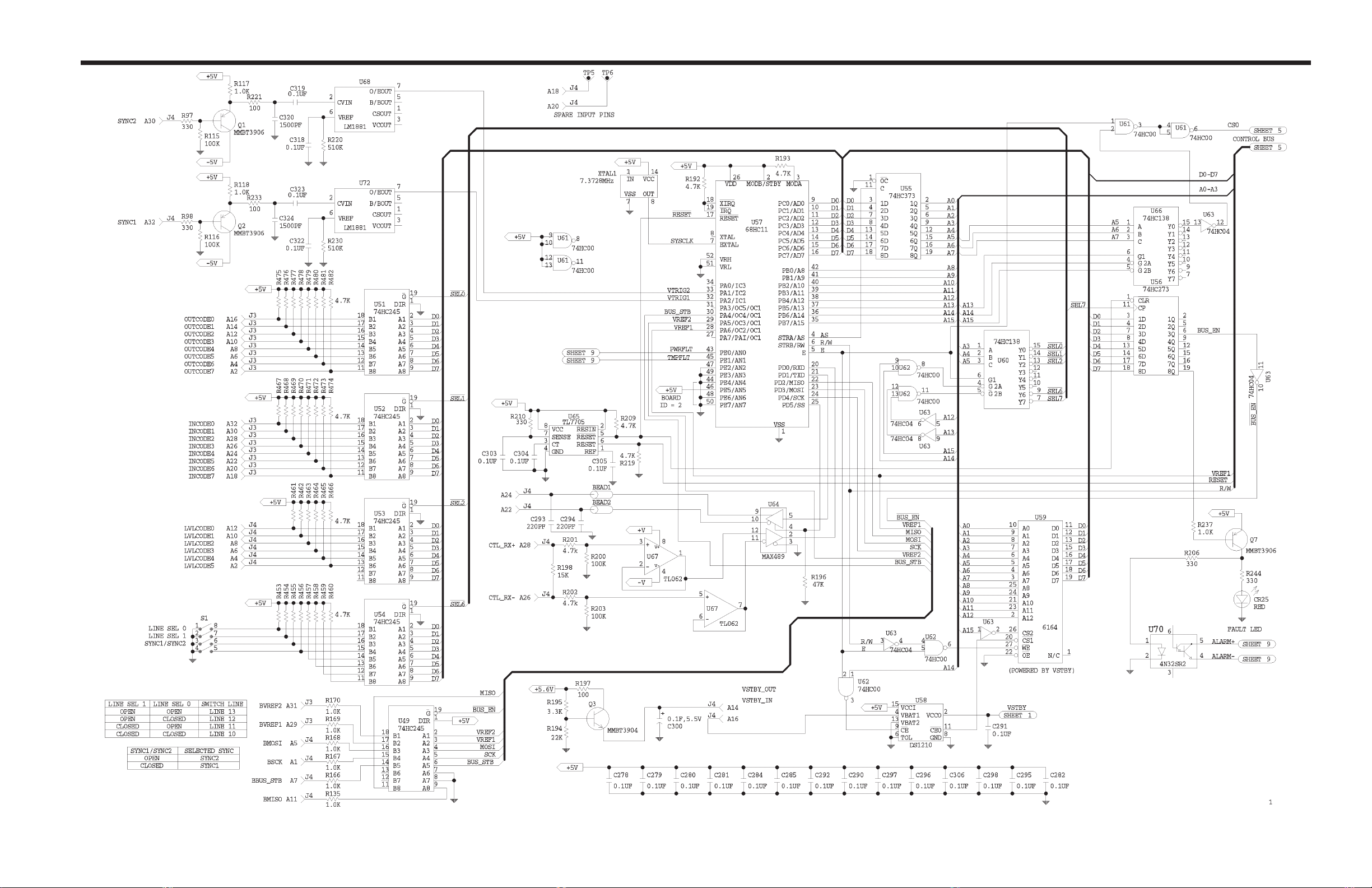
32X32 Digital Video Matrix Card Addendum
Schematic (Sheet 1 of 9) • 32X32 Digital Video Matrix Card (REV 04) • SC33-1353
4/98
32X32 Digital Video Matrix Card Addendum page 10
Page 86
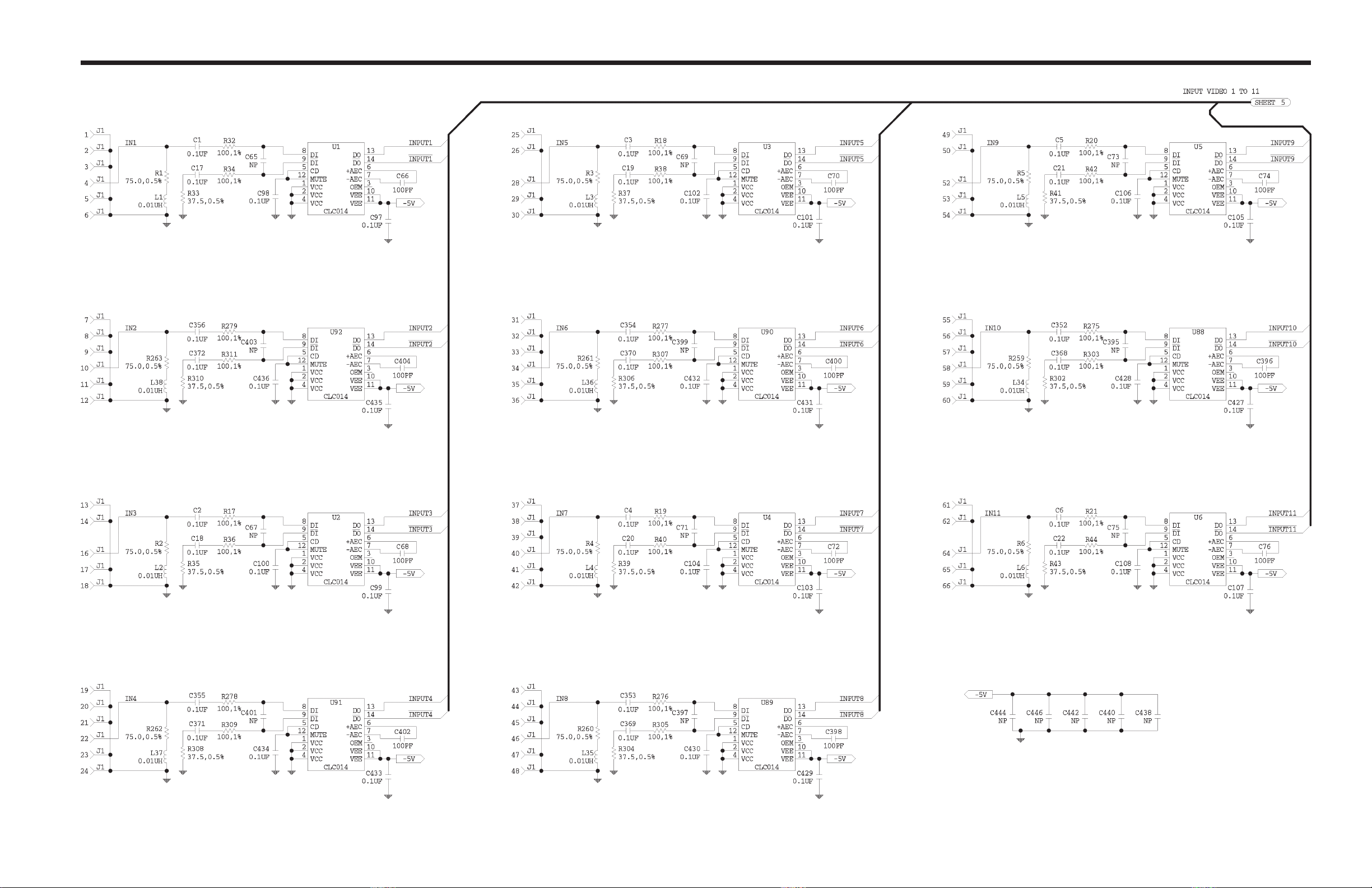
32X32 Digital Video Matrix Card Addendum
Schematic (Sheet 2 of 9) • 32X32 Digital Video Matrix Card (REV 04) • SC33-1353
4/98
32X32 Digital Video Matrix Card Addendum page 11
Page 87
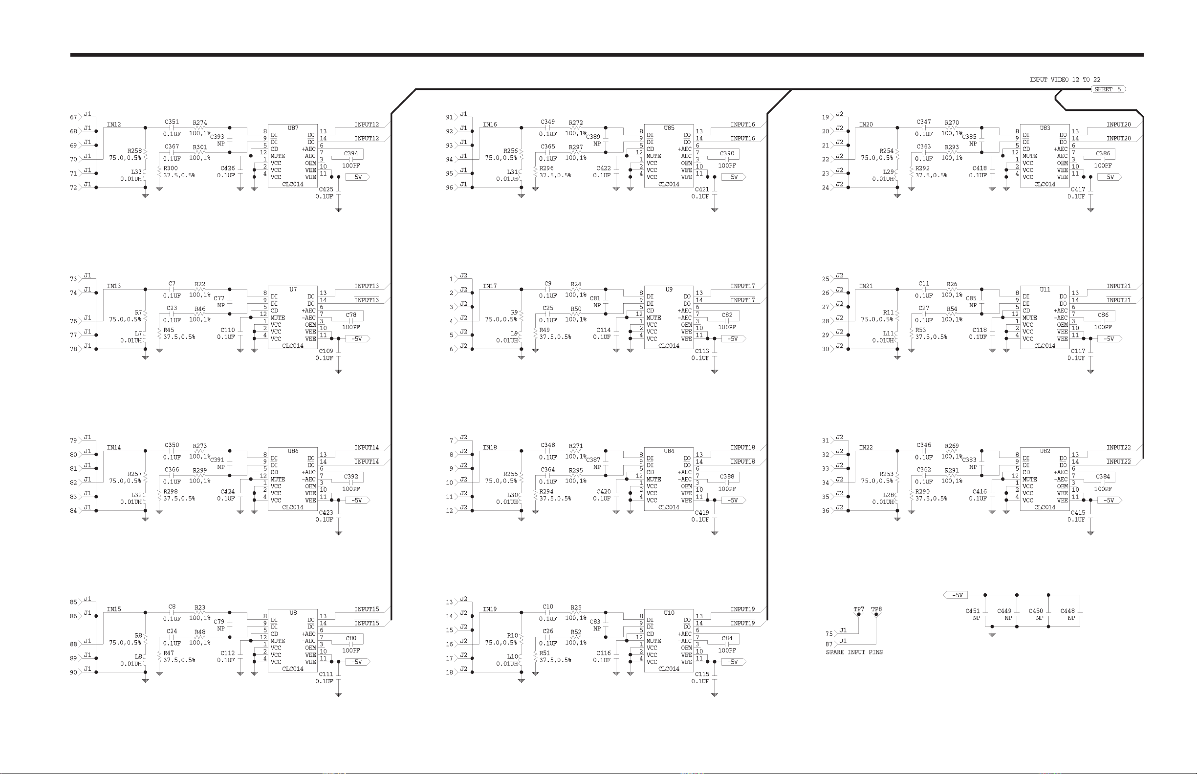
32X32 Digital Video Matrix Card Addendum
Schematic (Sheet 3 of 9) • 32X32 Digital Video Matrix Card (REV 04) • SC33-1353
4/98
32X32 Digital Video Matrix Card Addendum page 12
Page 88
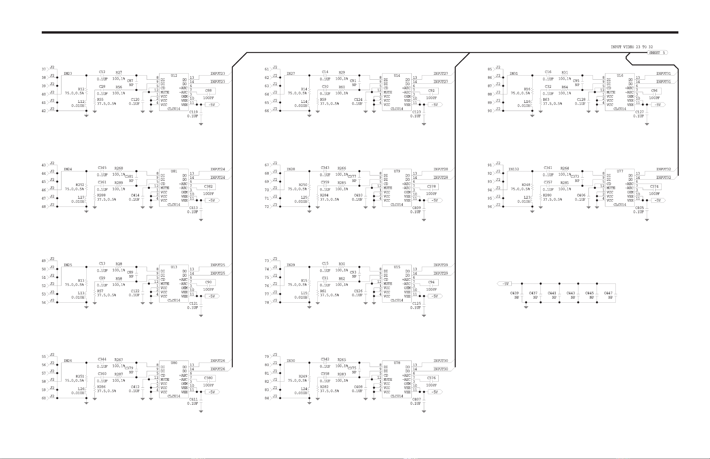
32X32 Digital Video Matrix Card Addendum
Schematic (Sheet 4 of 9) • 32X32 Digital Video Matrix Card (REV 04) • SC33-1353
4/98
32X32 Digital Video Matrix Card Addendum page 13
Page 89
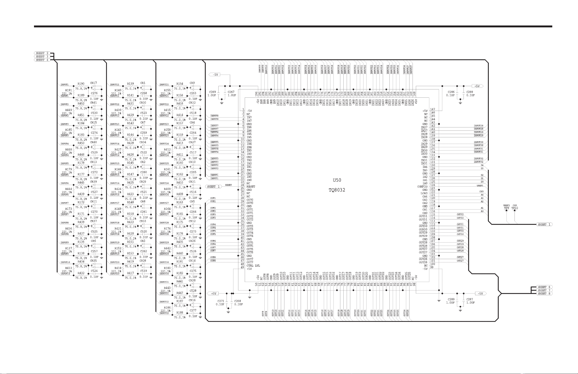
32X32 Digital Video Matrix Card Addendum
Schematic (Sheet 5 of 9) • 32X32 Digital Video Matrix Card (REV 04) • SC33-1353
4/98
32X32 Digital Video Matrix Card Addendum page 14
Page 90
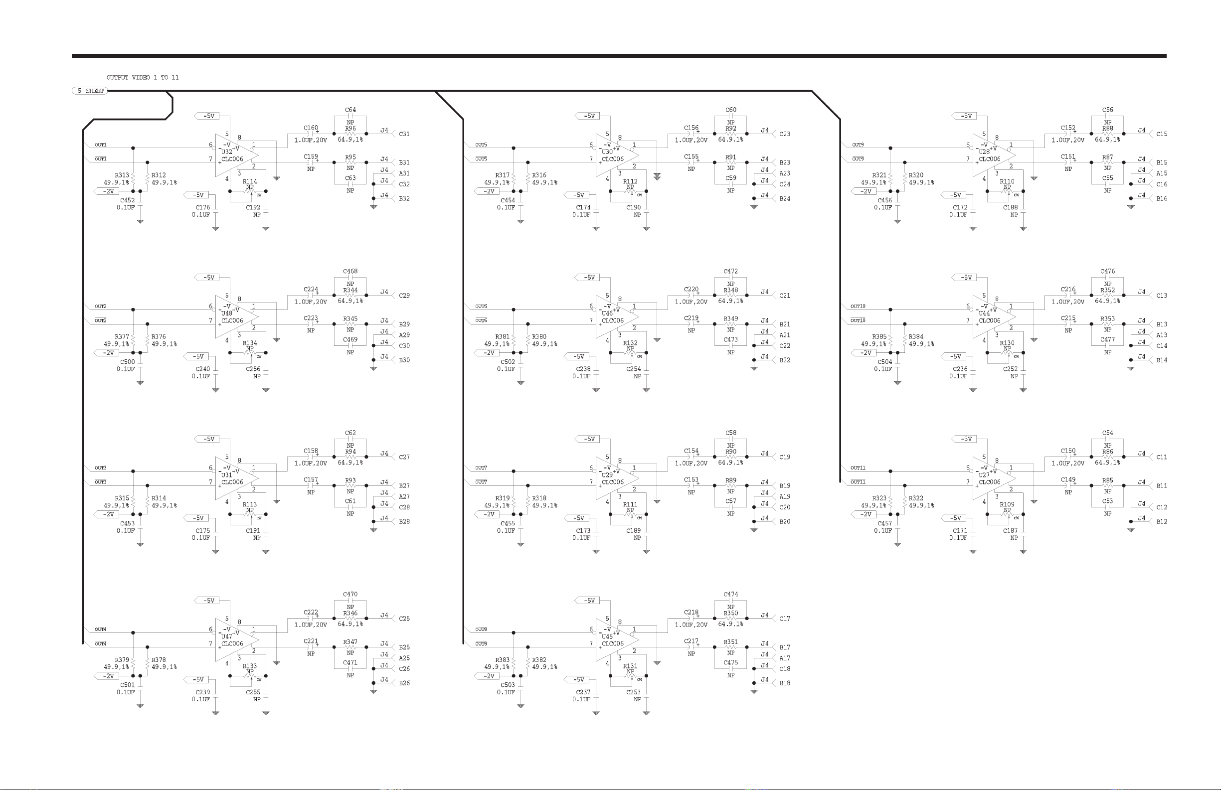
32X32 Digital Video Matrix Card Addendum
Schematic (Sheet 6 of 9) • 32X32 Digital Video Matrix Card (REV 04) • SC33-1353
4/98
32X32 Digital Video Matrix Card Addendum page 15
Page 91
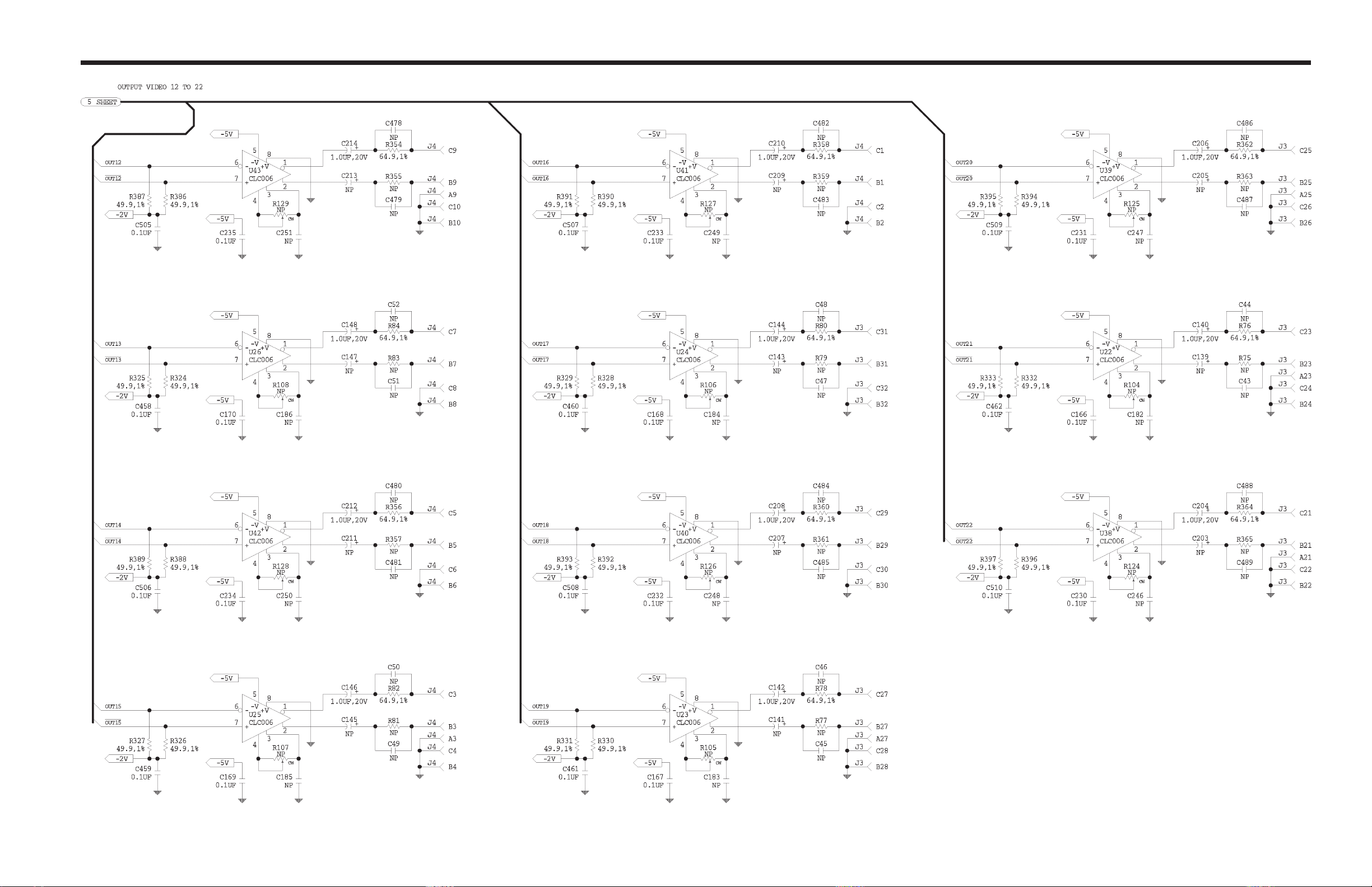
32X32 Digital Video Matrix Card Addendum
Schematic (Sheet 7 of 9) • 32X32 Digital Video Matrix Card (REV 04) • SC33-1353
4/98
32X32 Digital Video Matrix Card Addendum page 16
Page 92
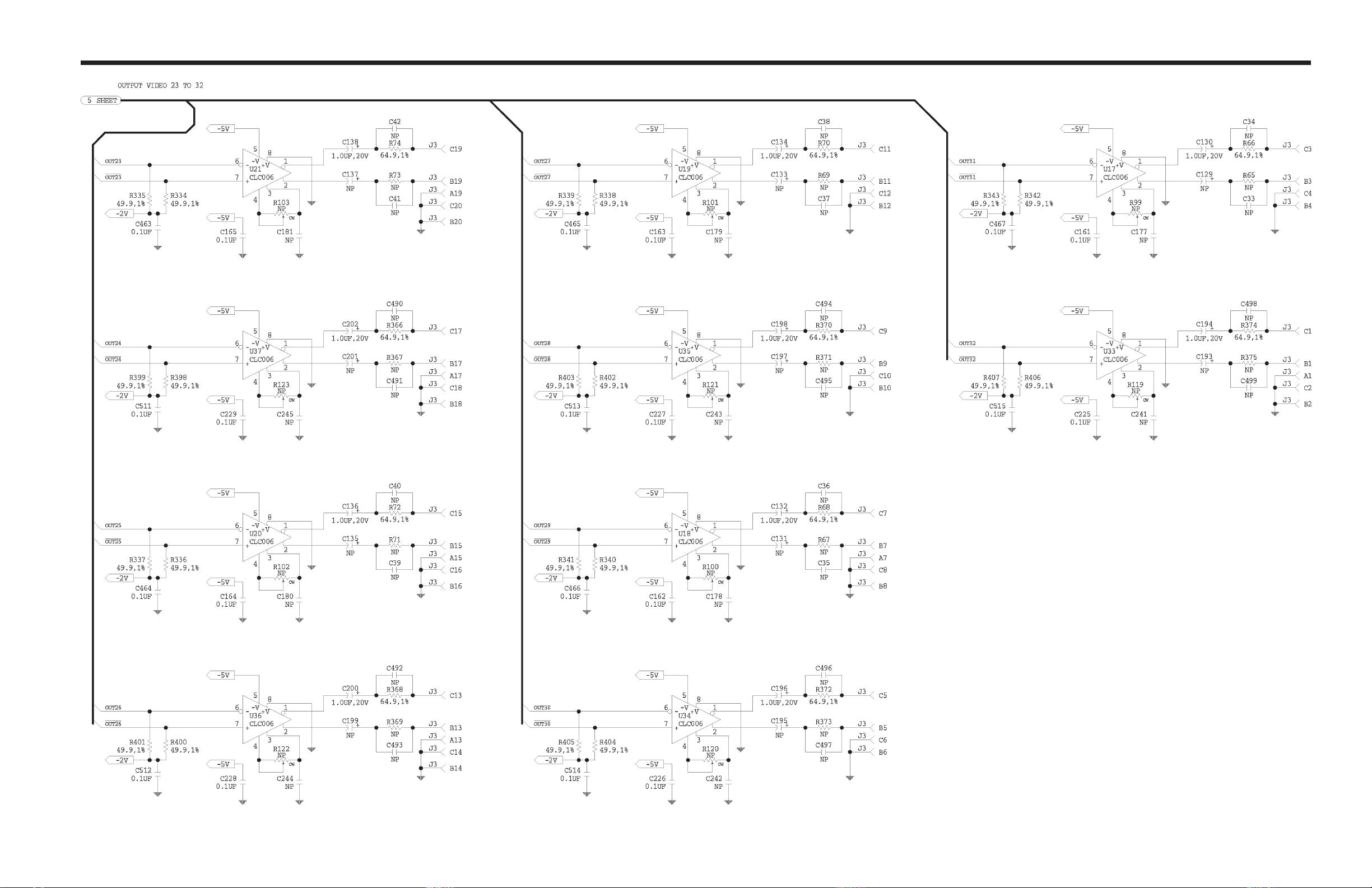
32X32 Digital Video Matrix Card Addendum
Schematic (Sheet 8 of 9) • 32X32 Digital Video Matrix Card (REV 04) • SC33-1353
4/98
32X32 Digital Video Matrix Card Addendum page 17
Page 93
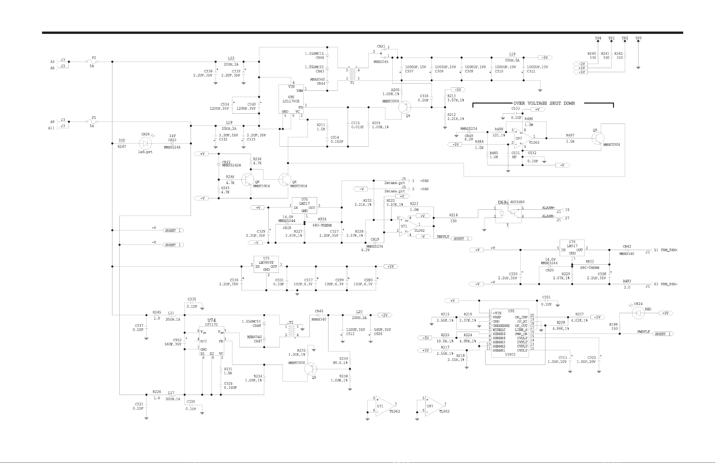
32X32 Digital Video Matrix Card Addendum
Schematic (Sheet 9 of 9) • 32X32 Digital Video Matrix Card (REV 04) • SC33-1353
4/98
32X32 Digital Video Matrix Card Addendum page 18
 Loading...