

Page 1
Peregrine Technology CO.,LTD.
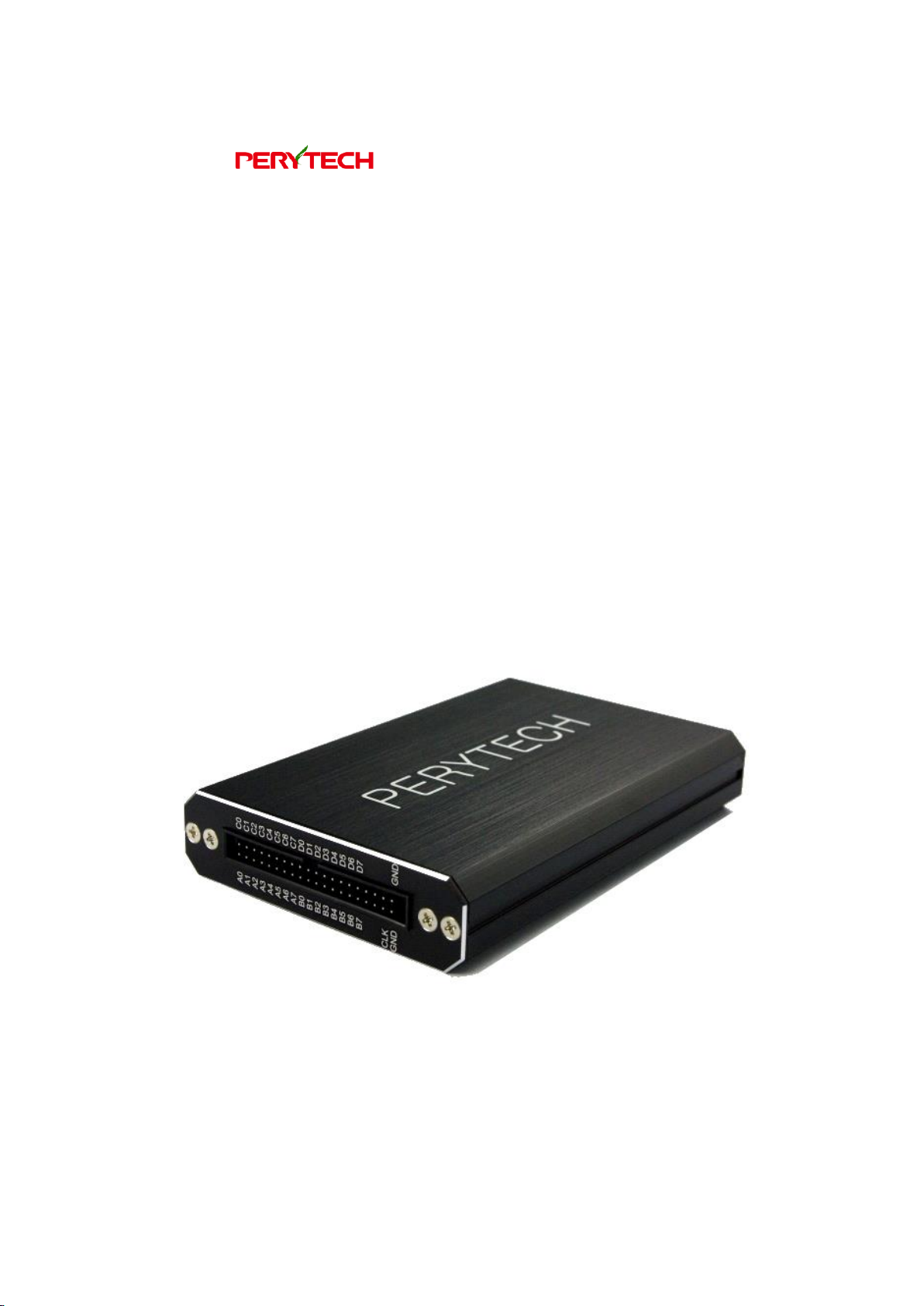
Logic Analyzer
User Manual
Page 2

沛瑞科技股份有限公司 TEL:886-2-2984-0000
www.perytech.com Peregrine Technology CO., LTD. FAX:886-2-2983-9999
1
Contents
Safe Use Specifications ........................................................................................................................... 3
1. System Requirement ....................................................................................................................... 4
2. Package Content ............................................................................................................................... 5
3. Exterior Appearance of the Logic Analyzer ........................................................................... 6
4. Software Installation ....................................................................................................................... 7
5. Logic Analyzer Software Operating Instructions ............................................................... 8
5.1. Quick start ....................................................................................................................................... 8
5.2. Setting the trigger condition ............................................................................................... 10
5.3. Setting the size of the memory and the sampling rate ............................................ 11
5.4. Setting trigger position .......................................................................................................... 12
5.5. Screen scaling ............................................................................................................................. 13
5.6. Move screen ................................................................................................................................ 14
5.7. Move the previous/next waveform edge ....................................................................... 15
5.8. Hot key list .................................................................................................................................... 16
5.9. Channel editing (add, delete, rename) ............................................................................ 17
5.10. Cursor function ...................................................................................................................... 18
5.11. Bus decoding function ....................................................................................................... 19
5.12. Bus packet list function ...................................................................................................... 23
5.13. Search bus data ..................................................................................................................... 24
5.14. Bus displayed as analog type .......................................................................................... 25
5.15. File function ............................................................................................................................. 26
5.16. Synchronizing waveforms from two files ................................................................... 27
5.17. Printing function ................................................................................................................... 29
5.18. Data export function ........................................................................................................... 30
5.19. External clock input .............................................................................................................. 33
5.20. Trigger width ........................................................................................................................... 35
5.21. Set trigger voltage ................................................................................................................ 37
5.22. Delay trigger ........................................................................................................................... 38
5.23. Data filter .................................................................................................................................. 39
5.24. Noise filter ................................................................................................................................ 41
5.25. Data inverse function .......................................................................................................... 42
Page 3

沛瑞科技股份有限公司 TEL:886-2-2984-0000
www.perytech.com Peregrine Technology CO., LTD. FAX:886-2-2983-9999
2
5.26. Packet trigger function ....................................................................................................... 44
5.27. Frequency counter function ............................................................................................. 45
5.28. Compression function ........................................................................................................ 46
6. Specification .................................................................................................................................... 48
Page 4

沛瑞科技股份有限公司 TEL:886-2-2984-0000
www.perytech.com Peregrine Technology CO., LTD. FAX:886-2-2983-9999
3
Safe Use Specifications
Thank you for choosing Perytech instruments. Before you start using our instrument,
please read the safe use specifications and understand the accurate method of use.
When using the instrument(s), please follow the safety rules to ensure the product is
functioning normally.
Please do not remove the outer casing: removing the outer casing can cause
electrocution and can damage the internal components.
Please connect the grounding end correctly: please do not connect the grounding
end to the power source to prevent damage to the logic analyzer and computer.
Please do not use oscilloscope in high temperatures and high humidity environments
or near flammable materials. This is to prevent damage to the logic analyzer.
If the instrument will not be used for a long time, please remove the USB cable to
conserve power.
Page 5

沛瑞科技股份有限公司 TEL:886-2-2984-0000
www.perytech.com Peregrine Technology CO., LTD. FAX:886-2-2983-9999
4
1. System Requirement
◆ Microsoft Windows XP/Vista /Windows 7/Windows 8/Windows 10 operating
system (including 32 & 64).
◆ USB 2.0 port.
Page 6
沛瑞科技股份有限公司 TEL:886-2-2984-0000
www.perytech.com Peregrine Technology CO., LTD. FAX:886-2-2983-9999
5
2. Package Content
Product Name
Quantity
Logic analyzer
1
USB cable
1
8P colored test wire
2 or 4*
2P black test wire
1
1P white test wire
1
Clips
18 or 36*
Software CD
1
*The 16 channel model has two sets of 8P colored test wire and 18 clips. The 32
channel model has four sets of 8P colored test wire and 36 clips.
Page 7
沛瑞科技股份有限公司 TEL:886-2-2984-0000
www.perytech.com Peregrine Technology CO., LTD. FAX:886-2-2983-9999
6
3. Exterior Appearance of the Logic Analyzer
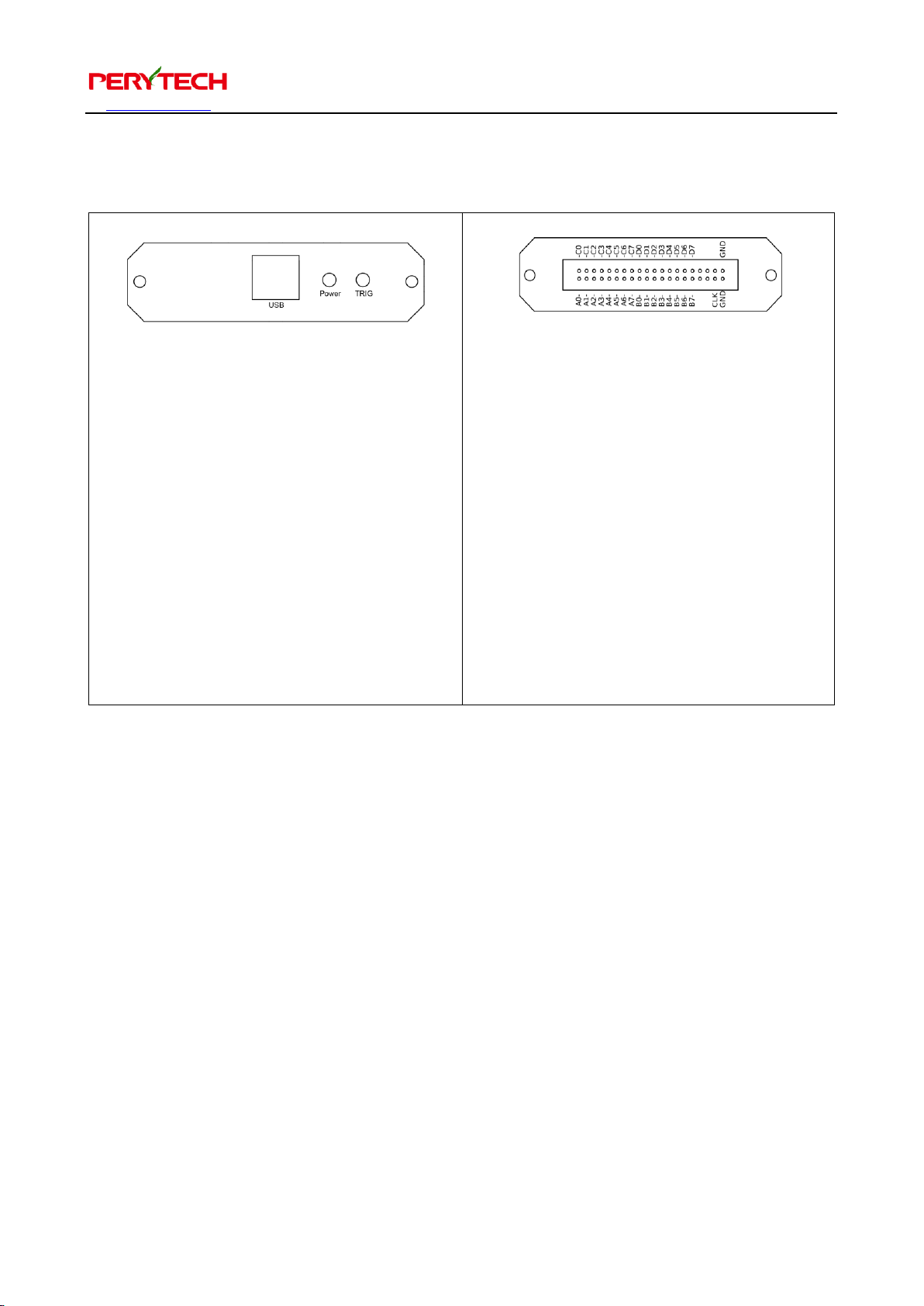
⚫ USB Port: interface between the logic
analyzer and computer
communication.
⚫ Power LED: when power supply is
normal this will shine red light.
⚫ TRIG LED: when the signal triggers
this will shine green light.
⚫ A0 - A7: signal input Port A
⚫ B0 - B7: signal input Port B
⚫ C0 – C7: signal input Port C
⚫ D0 – D7: signal input Port D
⚫ GND: ground
⚫ CLK: exterior clock input.
Page 8
沛瑞科技股份有限公司 TEL:886-2-2984-0000
www.perytech.com Peregrine Technology CO., LTD. FAX:886-2-2983-9999
7
4. Software Installation
The attached CD contains the LA installation software. The file name is
“LA_Install_V1.xx.exe” and the xx is the edition number. You can also download the
installation software from the Perytech website. Implement to install the software.
Software installation is very simple. Just press “Next.” The driver will also be installed
together. After installation is complete, an “LA” shortcut will appear on the desktop
and in the start function, as shown below.
Page 9
沛瑞科技股份有限公司 TEL:886-2-2984-0000
www.perytech.com Peregrine Technology CO., LTD. FAX:886-2-2983-9999
8
5. Logic Analyzer Software Operating Instructions
5.1. Quick start
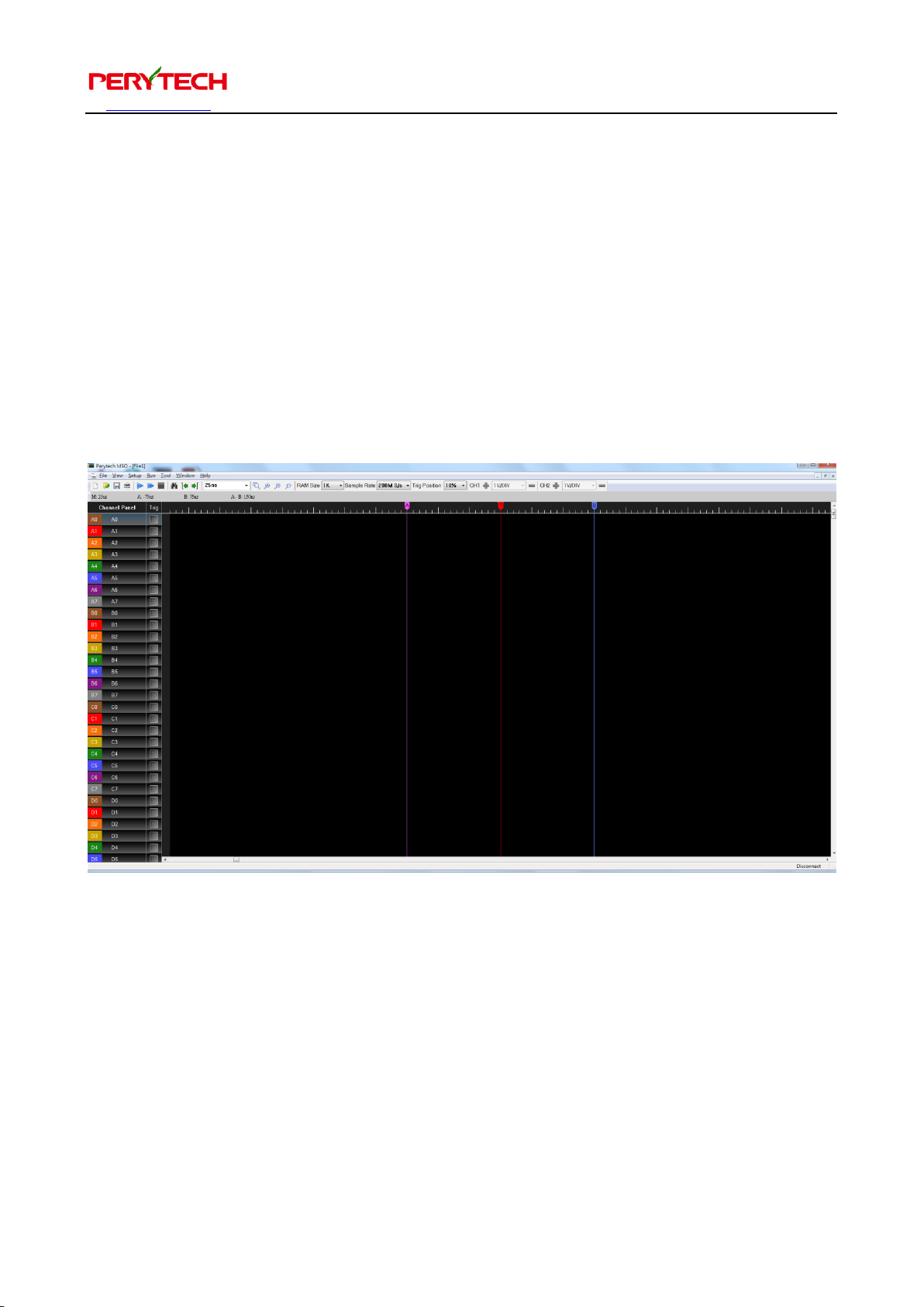
Click the LA shortcut on the desktop to activate the LA software. The following figure
is the software screen for the 32 channel model logic analyzer. If the instrument is a 16
channel model then the channel number would be 16. Except for the different
number of channels, the operating method for the 16 and 32 channel logic analyzer is
the same.
Page 10
沛瑞科技股份有限公司 TEL:886-2-2984-0000
www.perytech.com Peregrine Technology CO., LTD. FAX:886-2-2983-9999
9
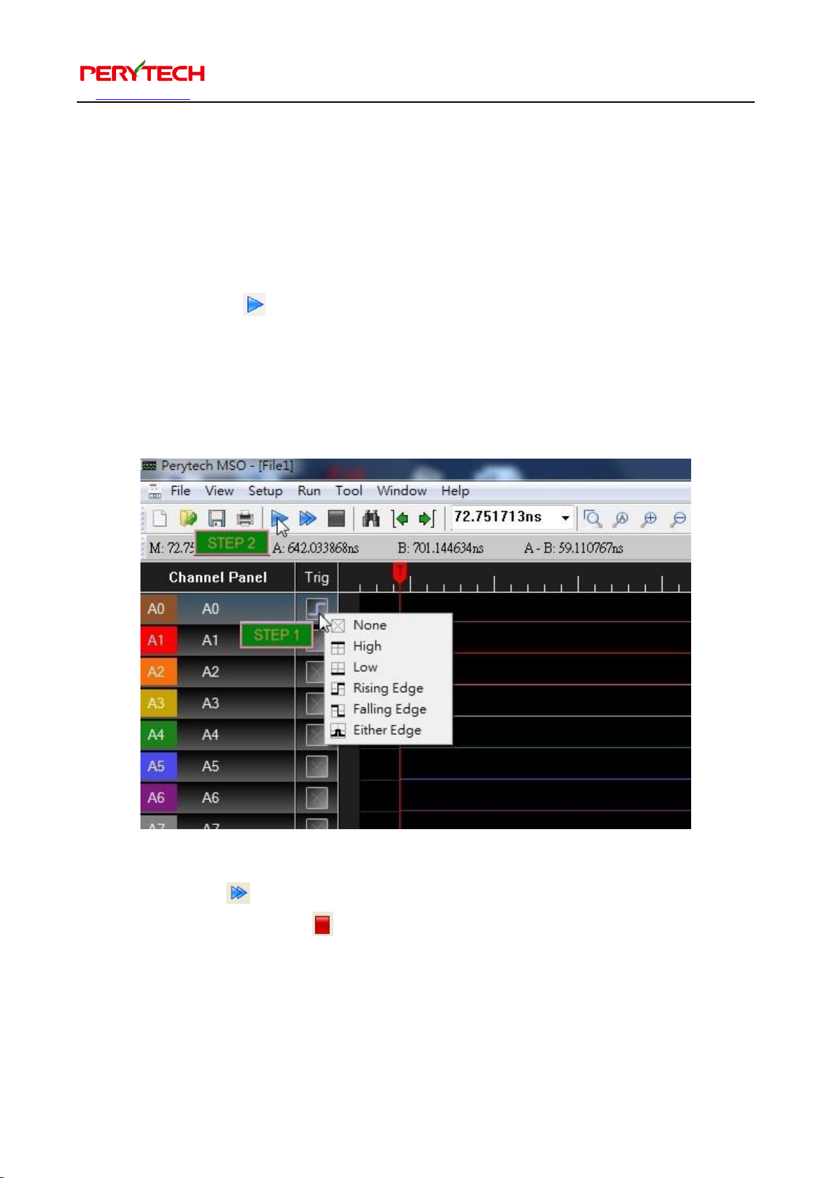
Basic operation of the logic analyzer requires only two steps:
1. Setting trigger conditions: click the Trig box (where the mouse cursor is in the
below figure) to set the trigger condition. Here we set the trigger condition as
Channel A0 rising edge.
2. Press the “Run” button.
After pressing the “Run” button, the logic analyzer will start to detect trigger signals.
When the trigger signal appears, the analyzer will transmit the data from the logic
analyzer back to the PC. The PC screen will show the waveform.
The “Repeat Run” next to the Run button is used to repeat the Run. If you wish to
stop, press the “Stop” button on the side at any time.
Page 11
沛瑞科技股份有限公司 TEL:886-2-2984-0000
www.perytech.com Peregrine Technology CO., LTD. FAX:886-2-2983-9999
10
5.2. Setting the trigger condition
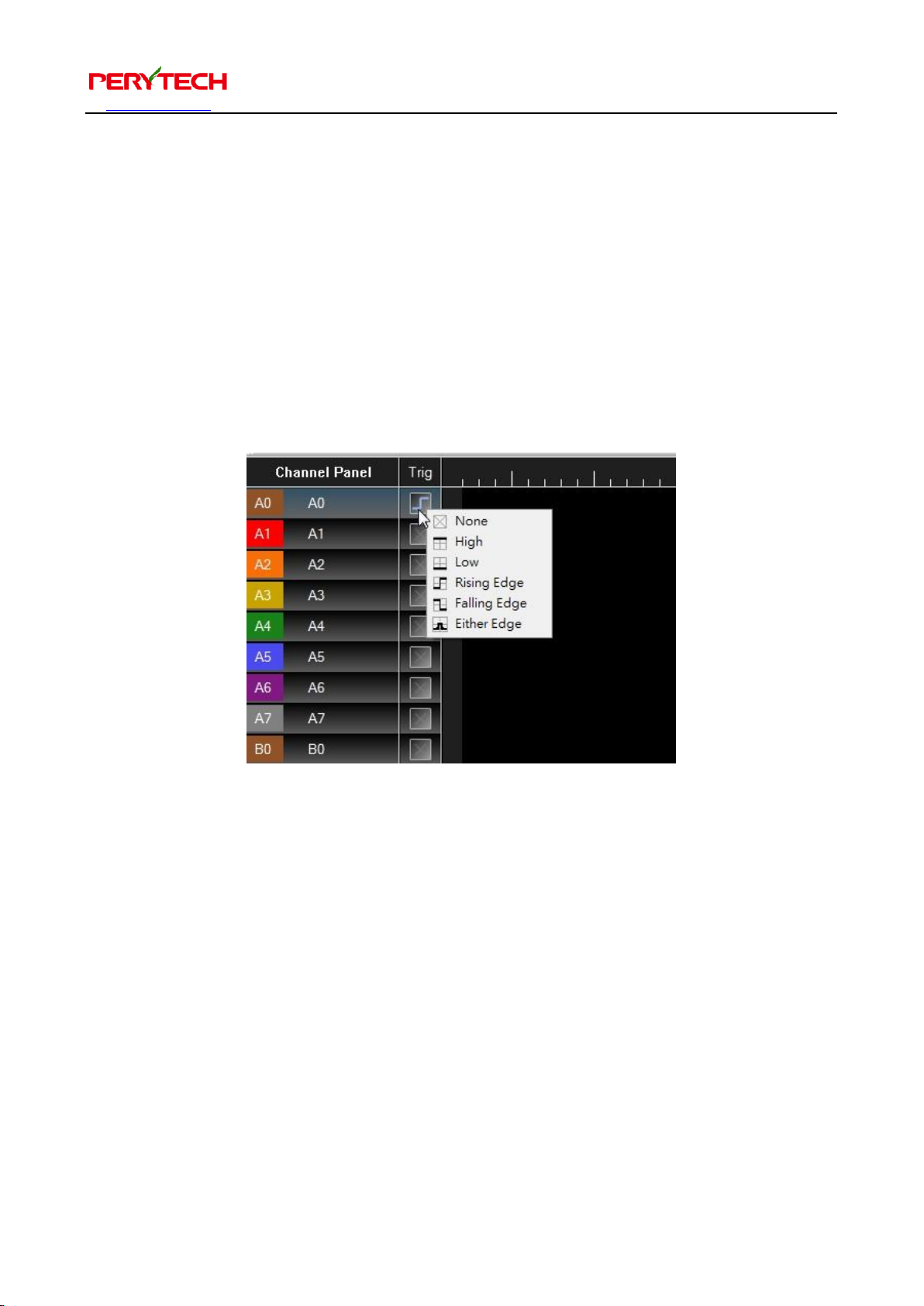
Click the Trig box (where the mouse cursor is located in the following figure) to set the
trigger condition. Click the mouse’s left button to cycle and change the trigger
condition. Click the mouse’s right button to display the trigger menu, shown below.
The menu can be used to select trigger conditions.
There are six trigger conditions to choose from: None, Rising Edge, Failing Edge,
Either Edge, High, and Low.
Because edge trigger (rising edge, failing edge, and either edge) is an instant action,
only one channel can be set at the edge trigger at the same time. Multiple channels
can be set at the same time for the level trigger (High, Low). Only when the signal
satisfies all set conditions will the logic analyzer be triggered.
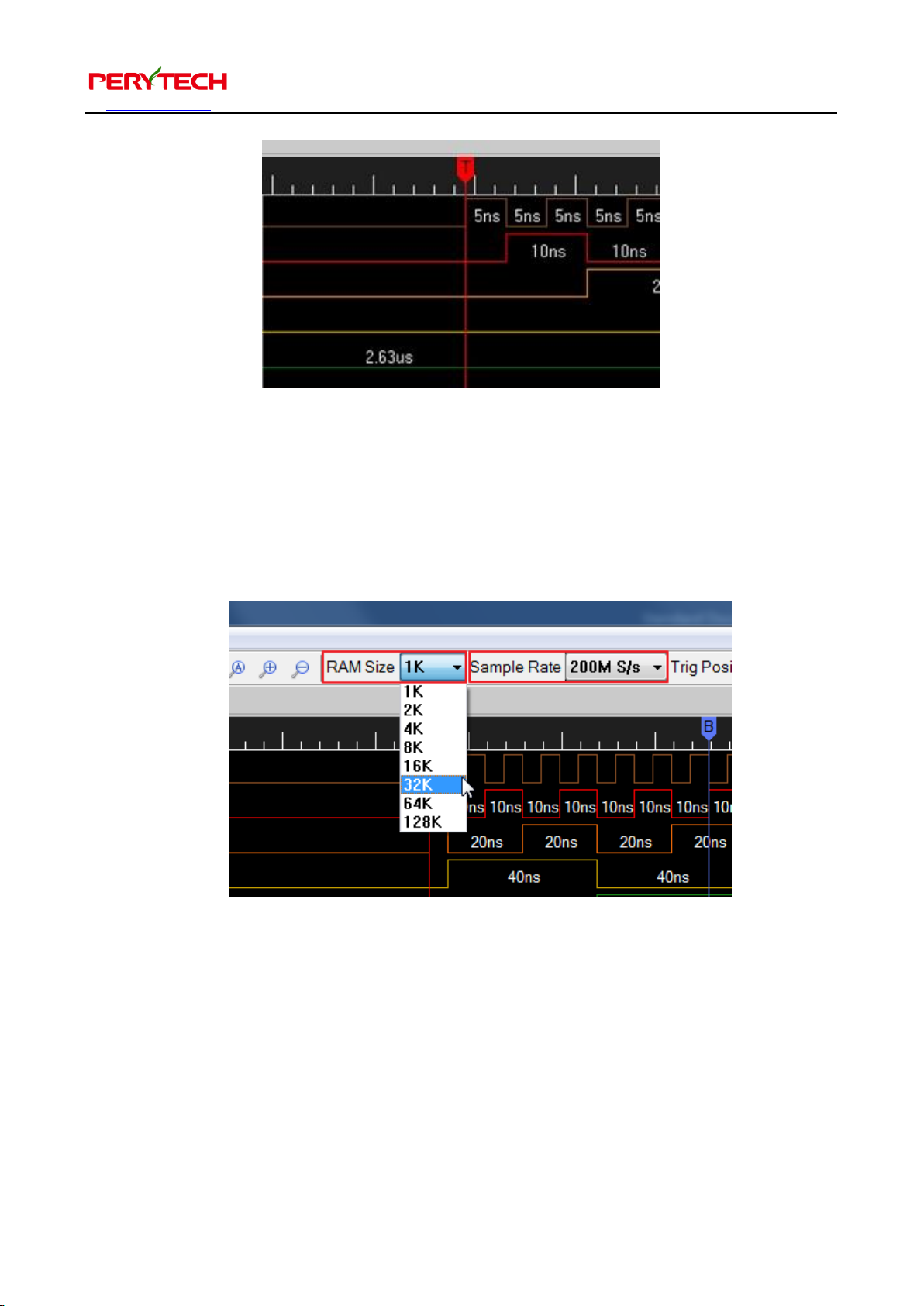
The trigger point is indicated by the red T cursor, as shown below. You can also use Alt
+ T to move the screen to the trigger point position.
Page 12
沛瑞科技股份有限公司 TEL:886-2-2984-0000
www.perytech.com Peregrine Technology CO., LTD. FAX:886-2-2983-9999
11
5.3. Setting the size of the memory and the sampling rate
Use the “RAM Size” and “Sample Rate” pull down menu in the toolbar to select
memory size and sampling rate, as shown in the below figure.
Page 13
沛瑞科技股份有限公司 TEL:886-2-2984-0000
www.perytech.com Peregrine Technology CO., LTD. FAX:886-2-2983-9999
12
5.4. Setting trigger position
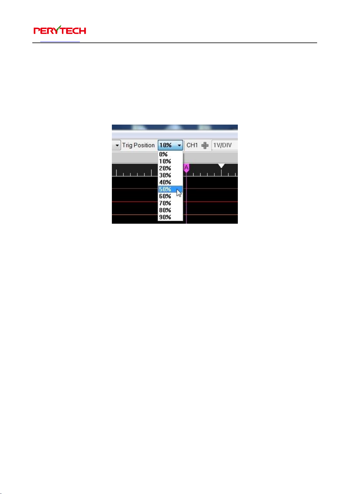
Use the “Trig Position” pull-down menu to select the trigger position, as shown below.
For example, if you select 20%, the trigger point will be in the front 20% position of all
the data. The default value is 10%.
Sometimes the trigger will be in front of the set position. For example, the trigger
setting is at 50%, but the trigger point is at the 20% position. This is because the
memory has not yet filled in the data in front of the 50% before the trigger signal
appeared. Thus, there will be less data before the memory. You can set it so that the
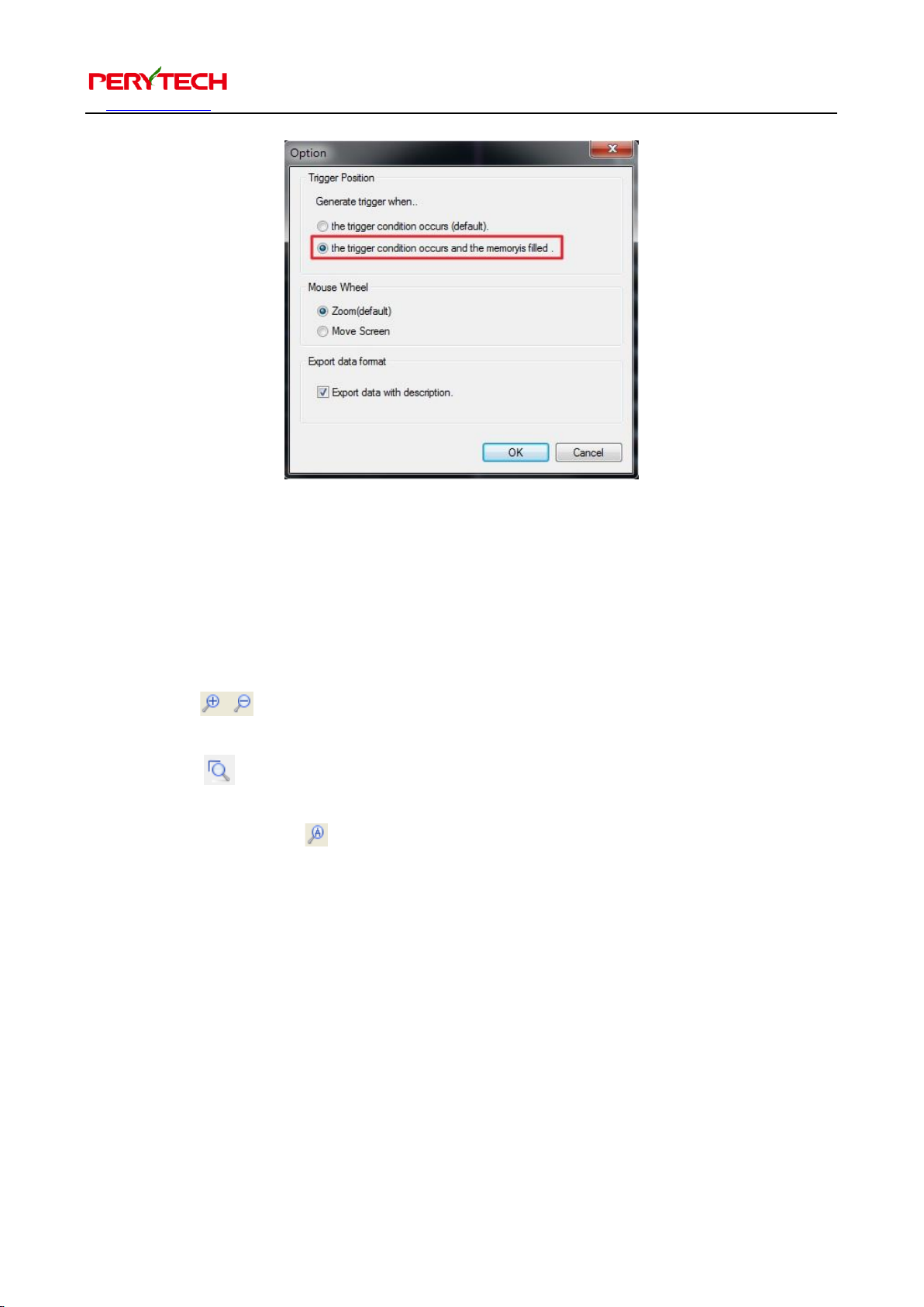
memory must be filled in before trigger can be activated. Open Tools → Option. Open
the Option window, as shown below. The Trigger Position default setting is “the
trigger condition occurs.” Change this to “the trigger condition occurs and the
memory is filled.” This way, the hardware will wait for the memory to be filled in
before detecting the trigger signal.
Page 14
沛瑞科技股份有限公司 TEL:886-2-2984-0000
www.perytech.com Peregrine Technology CO., LTD. FAX:886-2-2983-9999
13
5.5. Screen scaling
There are five ways to scale the screen:
1. Press the Ctrl key + mouse roller
2. Use the buttons in the toolbar
3. The “+ -” keys on the keyboard
4. Use the button in the toolbar. The function of this is to magnify the part
frame-selected with the mouse
5. The function of the button in the toolbar is to shrink all the waveforms into
the screen.
Page 15
沛瑞科技股份有限公司 TEL:886-2-2984-0000
www.perytech.com Peregrine Technology CO., LTD. FAX:886-2-2983-9999
14
5.6. Move screen
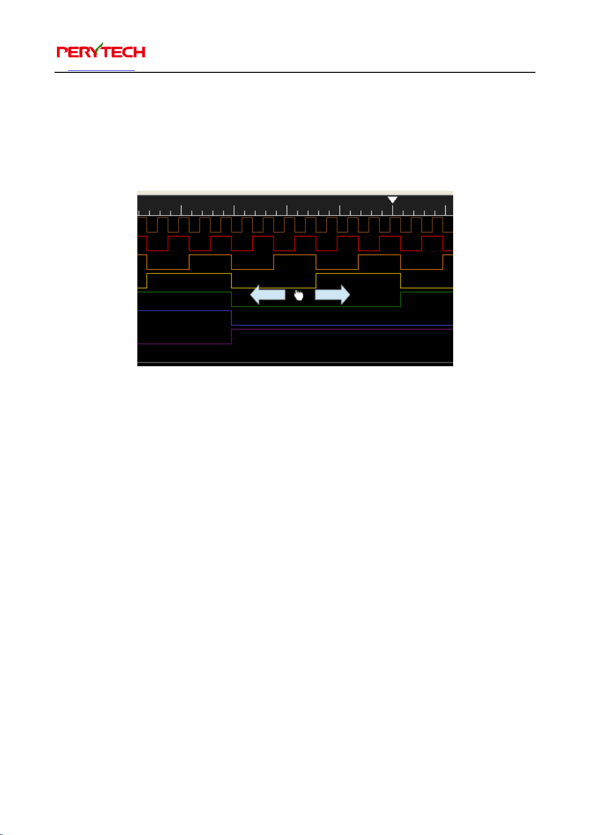
Press the right mouse button to drag the screen, as shown below. The mouse roller
can also be used scroll the screen.
The left /right button on the keyboard can also be used to move the waveform. Each
moving distance is one large grid. The Page Up/Page Down can also be used to move
the move waveform. The distance of each move is approximately 10 large grids.
Page 16
沛瑞科技股份有限公司 TEL:886-2-2984-0000
www.perytech.com Peregrine Technology CO., LTD. FAX:886-2-2983-9999
15
5.7. Move the previous/next waveform edge
The buttons in the toolbar can move the screen to the previous/next edge of
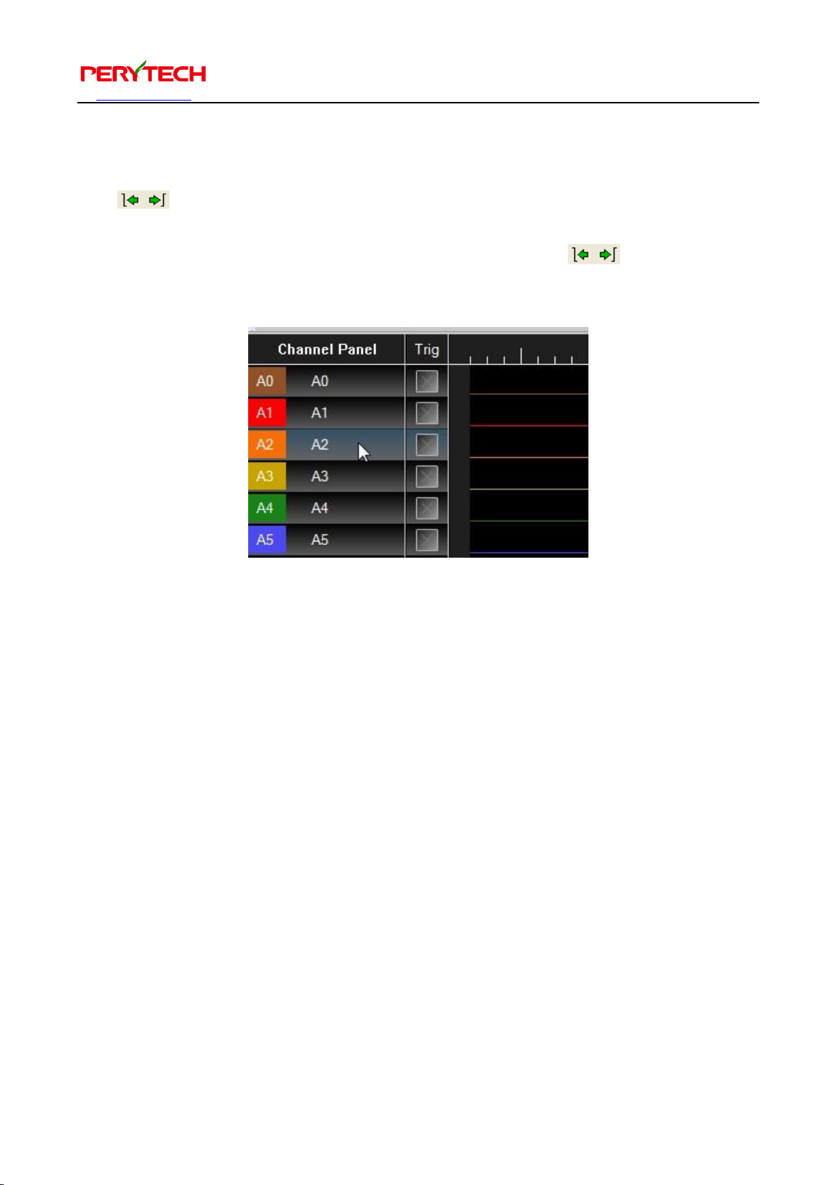
the waveform. This is useful for searching the waveforms. First, select the channel on
the left side Channel Panel (as shown below). Then press to move to the
next/previous edge of the waveform. The hot key is the “Ctrl + Left/Right” keys.
Page 17
沛瑞科技股份有限公司 TEL:886-2-2984-0000
www.perytech.com Peregrine Technology CO., LTD. FAX:886-2-2983-9999
16
5.8. Hot key list
The following is a list of hot keys related to screen operations
Hot key
Function
Right mouse right button
Drag screen
Mouse roller
Move screen
Keyboard left/right key
Left/right move screen (one
grid)
Keyboard Page Up/Page
Down key
Jump to previous page/next
page waveform
Ctrl + mouse roller
Screen scaling
Keyboard + - key
Screen scaling
Ctrl + keyboard left/right key
Go to the previous/next
waveform edge
Keyboard Page Up/Page
Down key
Left/right move screen (10
grids)
Left mouse button
Move cursor (A, B Bar)
Keyboard Alt + A/B/T key
Jump to A/B/T Bar position
Page 18
沛瑞科技股份有限公司 TEL:886-2-2984-0000
www.perytech.com Peregrine Technology CO., LTD. FAX:886-2-2983-9999
17
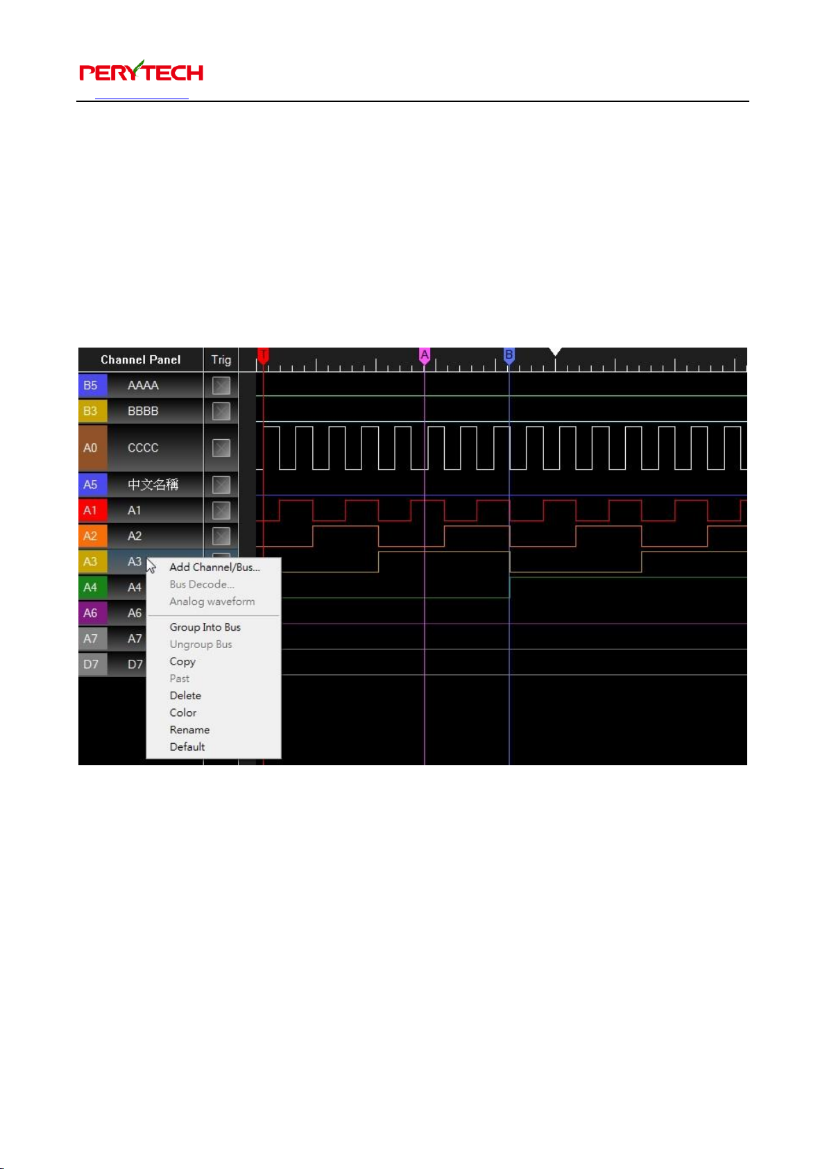
5.9. Channel editing (add, delete, rename)
There are many channel editing functions on the “Channel Panel” on the left side of
the screen. Click the mouse’s right button on the channel and a menu will be
displayed, as shown below. This menu can be used to add/delete channels, edit the
channel name, or change the channel color. The left mouse button can be used to
drag the channel. The mouse can also be used to adjust the channel height.
Page 19
沛瑞科技股份有限公司 TEL:886-2-2984-0000
www.perytech.com Peregrine Technology CO., LTD. FAX:886-2-2983-9999
18
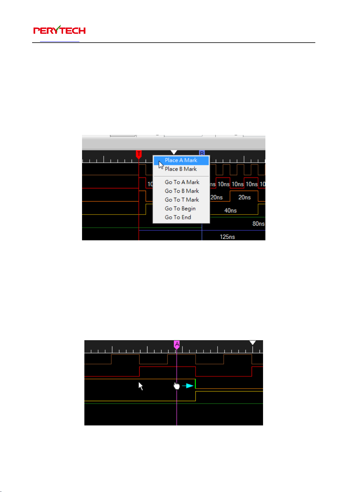
5.10. Cursor function
Click the right mouse button on the rule area above the waveform will show the
cursor menu, as shown below. You can place the A/B cursor or go to the A/B/T cursor
position (T: trigger cursor). You can also go to the beginning and go to the end
position.
Press the left mouse button to drag the cursor, as shown below. The cursor will
automatically align the waveform edge. If the mouse cursor moves close to the
waveform edge when dragging the cursor, the waveform’s edge will display green, as
shown below. If the left mouse button is released at this time, the cursor will
automatically align the edge.
Page 20
沛瑞科技股份有限公司 TEL:886-2-2984-0000
www.perytech.com Peregrine Technology CO., LTD. FAX:886-2-2983-9999
19
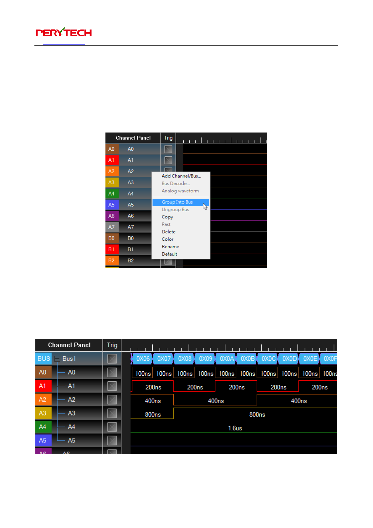
5.11. Bus decoding function
Press Ctrl + left mouse button on the left side Channel Panel to select the channel.
The selected channel will turn greyish-blue, as shown below. Press the mouse’s right
button to display the channel operation menu. Choose “Group Into Bus.”
Then the selected channels will be integrated into a bus, as shown below. Because the
bus decoding is not set, the displayed channel is in hexadecimal value.
Page 21
沛瑞科技股份有限公司 TEL:886-2-2984-0000
www.perytech.com Peregrine Technology CO., LTD. FAX:886-2-2983-9999
20
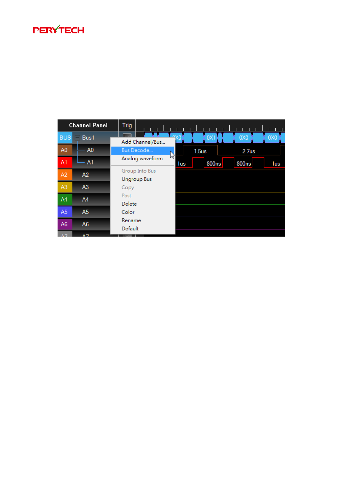
The following uses the I2C bus as an example to describe how to use the bus
decoding function.
First, we group the two I2C bus channels into a bus. Then we press the right mouse
button on the grouped bus and choose Bus Decode, as shown below.
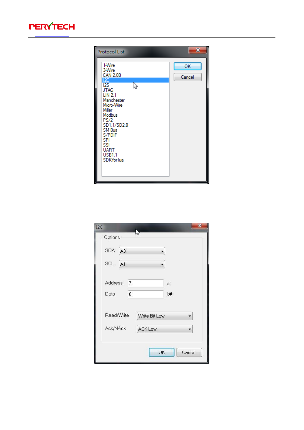
Next, the Protocol List window will appear, which is used to select the bus type to be
decoded. Select I2C and then press OK.
Page 22
沛瑞科技股份有限公司 TEL:886-2-2984-0000
www.perytech.com Peregrine Technology CO., LTD. FAX:886-2-2983-9999
21
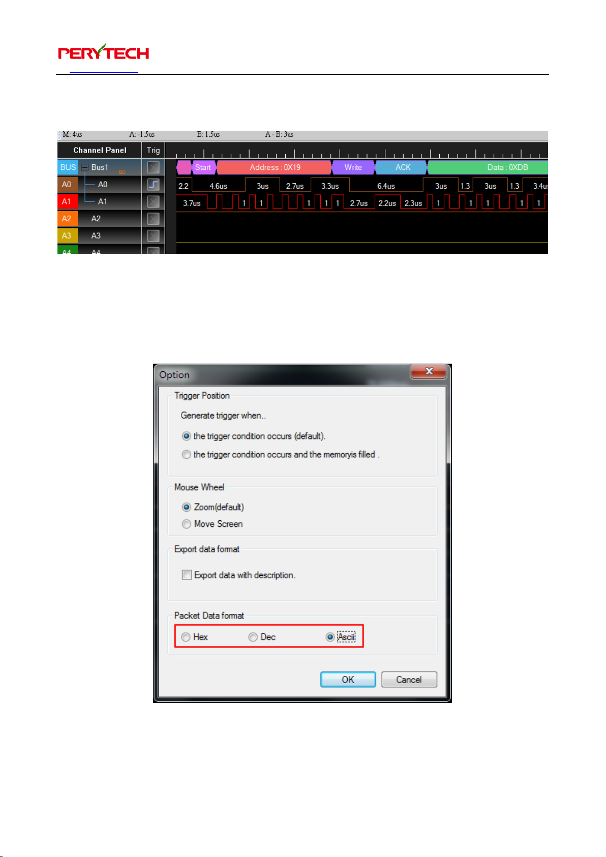
The parameter setting window will appear that is used to set the I2C’s channels and
parameters. Set according to the actual situation. Press OK after selection is complete.
Page 23
沛瑞科技股份有限公司 TEL:886-2-2984-0000
www.perytech.com Peregrine Technology CO., LTD. FAX:886-2-2983-9999
22
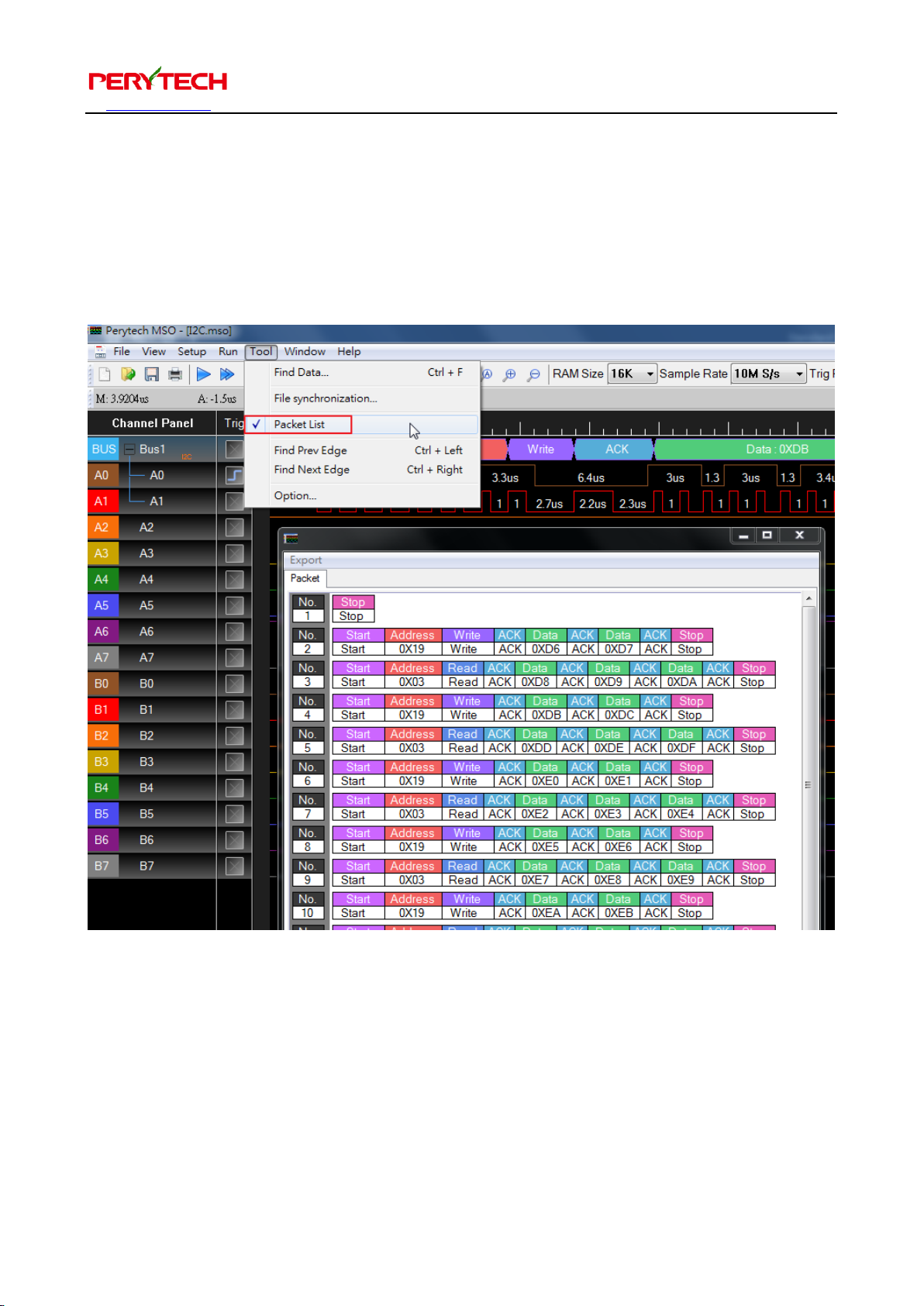
If the setting is correct the bus decoding result can be seen, as shown below.
The default bus decoding format is in hexadecimal (Hex) values. The user can also choose the
decimal or ASCII (the setting is in the Menu -> Option -> Packet Data Format) format.
Page 24
沛瑞科技股份有限公司 TEL:886-2-2984-0000
www.perytech.com Peregrine Technology CO., LTD. FAX:886-2-2983-9999
23
5.12. Bus packet list function
The packet list function can be used to conveniently analyze large quantity of data.
Open Tools → Packet List to show the bus packet list, as shown below.
Page 25
沛瑞科技股份有限公司 TEL:886-2-2984-0000
www.perytech.com Peregrine Technology CO., LTD. FAX:886-2-2983-9999
24
5.13. Search bus data
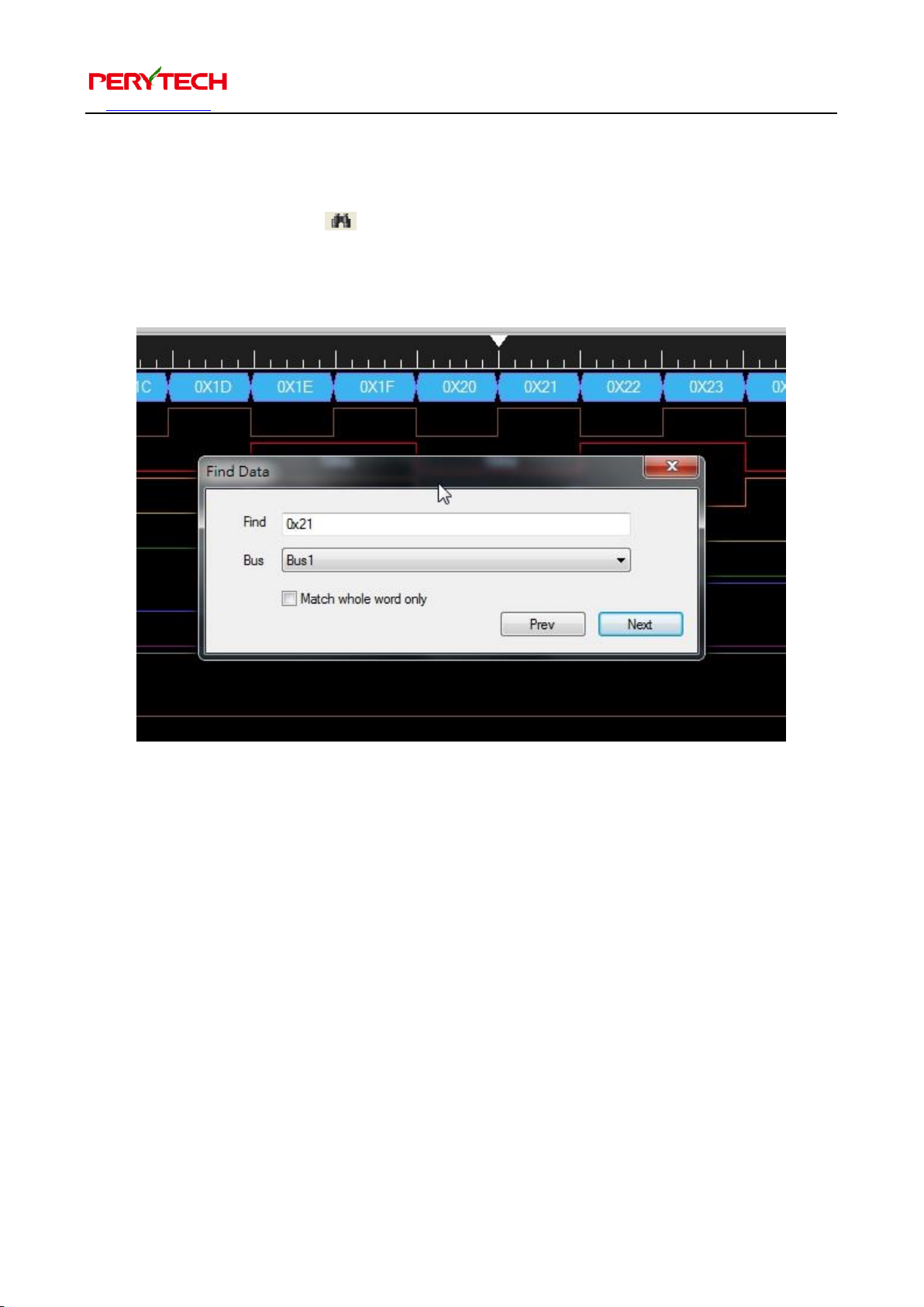
Click the binocular button in the toolbar to open the search function window, as
shown below. Input the search key words (here the example shows input 0x21) and
press “Next.” Packets that match the keywords will then appear on the screen.
Page 26
沛瑞科技股份有限公司 TEL:886-2-2984-0000
www.perytech.com Peregrine Technology CO., LTD. FAX:886-2-2983-9999
25
5.14. Bus displayed as analog type
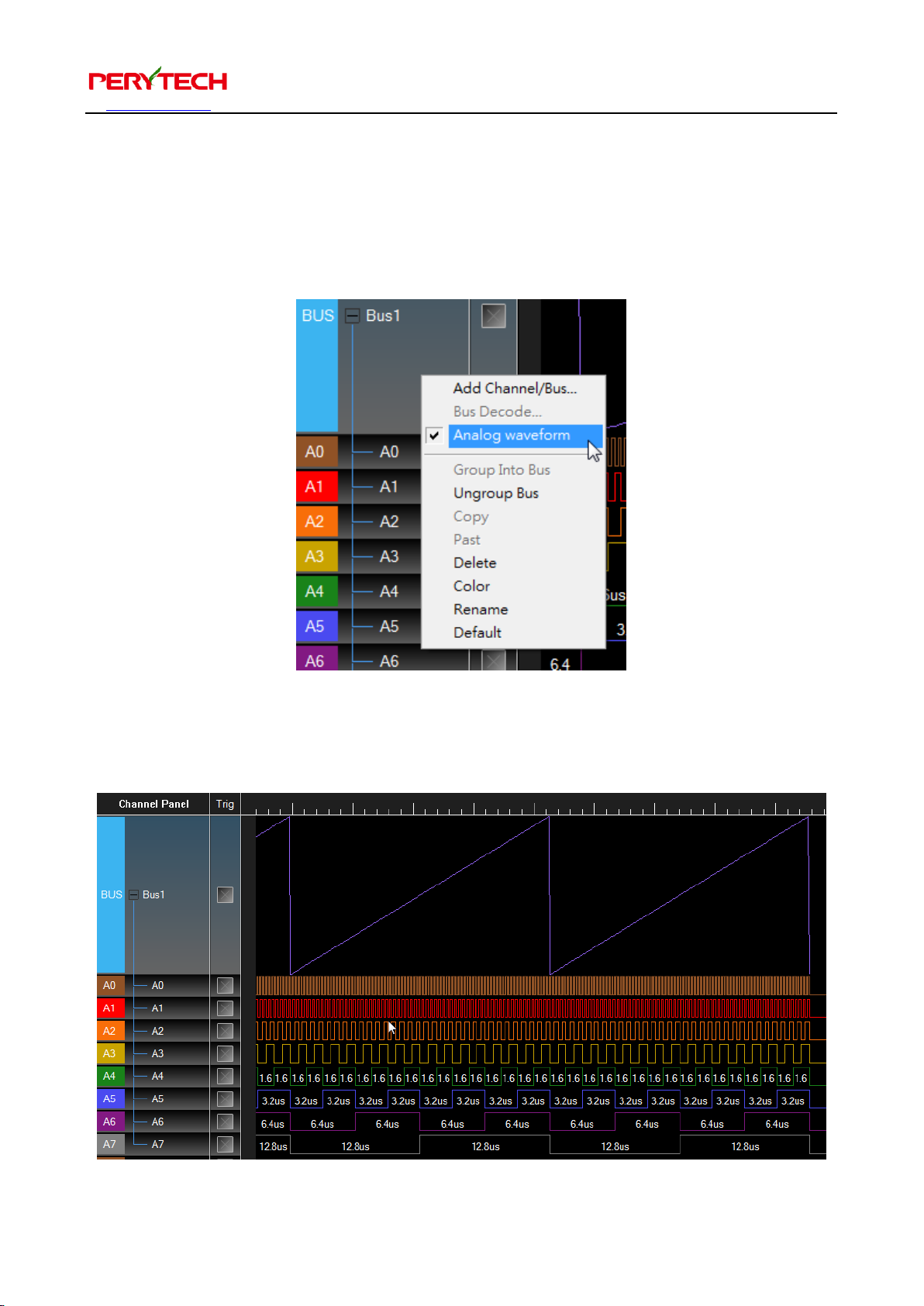
In addition to digital values, the bus can also be displayed as analog waveform. Press
the right mouse button on the bus and select the analog waveform.
The bus value will be displayed as analog waveform, as shown below.
Page 27
沛瑞科技股份有限公司 TEL:886-2-2984-0000
www.perytech.com Peregrine Technology CO., LTD. FAX:886-2-2983-9999
26
5.15. File function
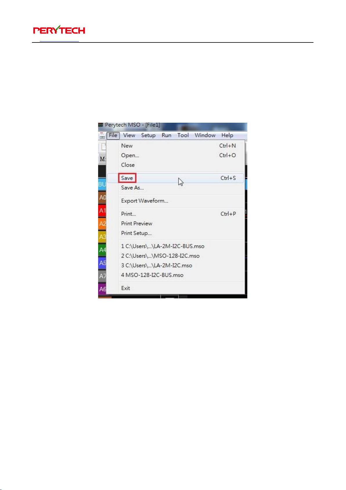
The “File” menu can be used to implement file related functions, as shown below.
When saving a file, the software setting will also be stored at the same time (such as
bus setting and trigger setting). The filename extension for saved files is *.MSO.
Page 28
沛瑞科技股份有限公司 TEL:886-2-2984-0000
www.perytech.com Peregrine Technology CO., LTD. FAX:886-2-2983-9999
27
5.16. Synchronizing waveforms from two files
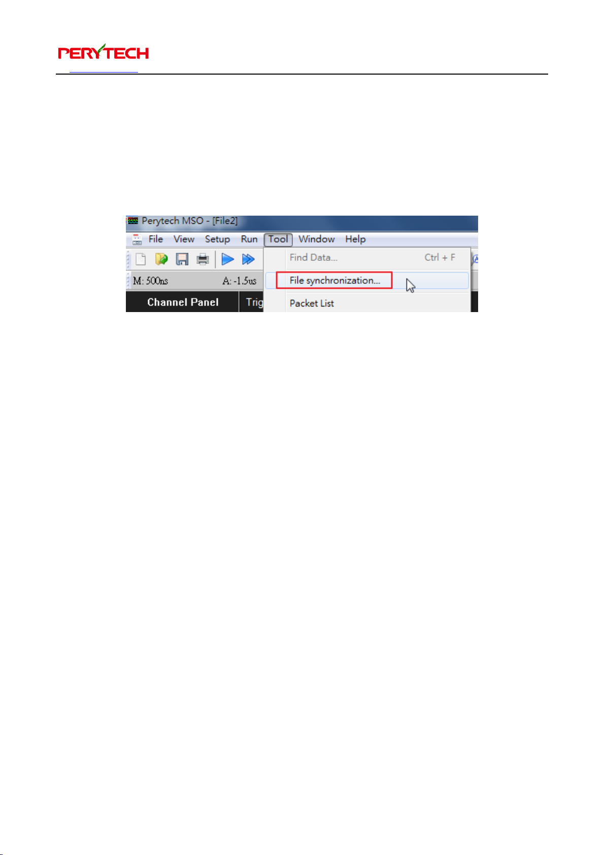
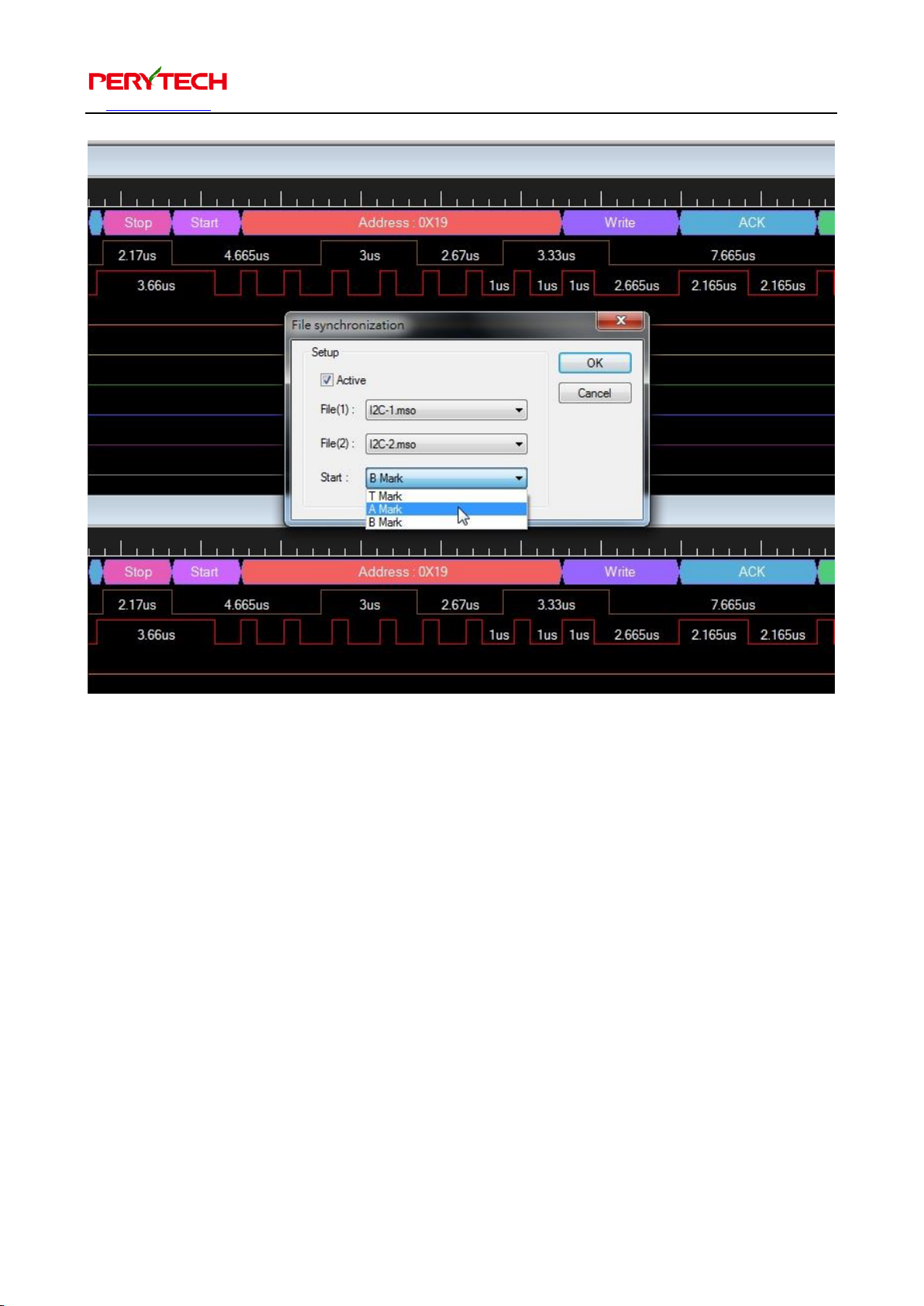
The software can simultaneously open two files for comparison. The file
synchronization function can synchronization move and scale the two files. The file
synchronization function is in Tool → File Synchronization, as shown below.
After selecting, the file synchronization window will appear, as shown below. When
synchronizing move, the synchronization starting point A, B, or T cursor can be
selected.
Page 29
沛瑞科技股份有限公司 TEL:886-2-2984-0000
www.perytech.com Peregrine Technology CO., LTD. FAX:886-2-2983-9999
28
Page 30
沛瑞科技股份有限公司 TEL:886-2-2984-0000
www.perytech.com Peregrine Technology CO., LTD. FAX:886-2-2983-9999
29
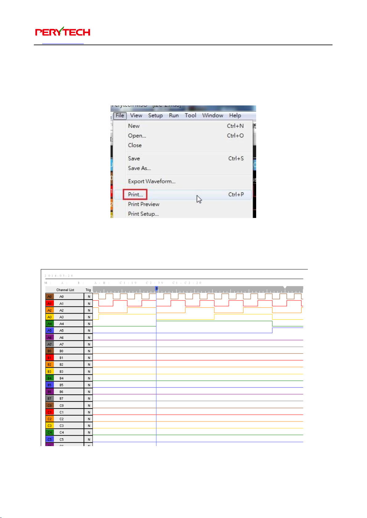
5.17. Printing function
The printing function is in the “File” menu under “Print,” as shown below.
To save on ink use, the print background is set as white, as shown below.
Page 31
沛瑞科技股份有限公司 TEL:886-2-2984-0000
www.perytech.com Peregrine Technology CO., LTD. FAX:886-2-2983-9999
30
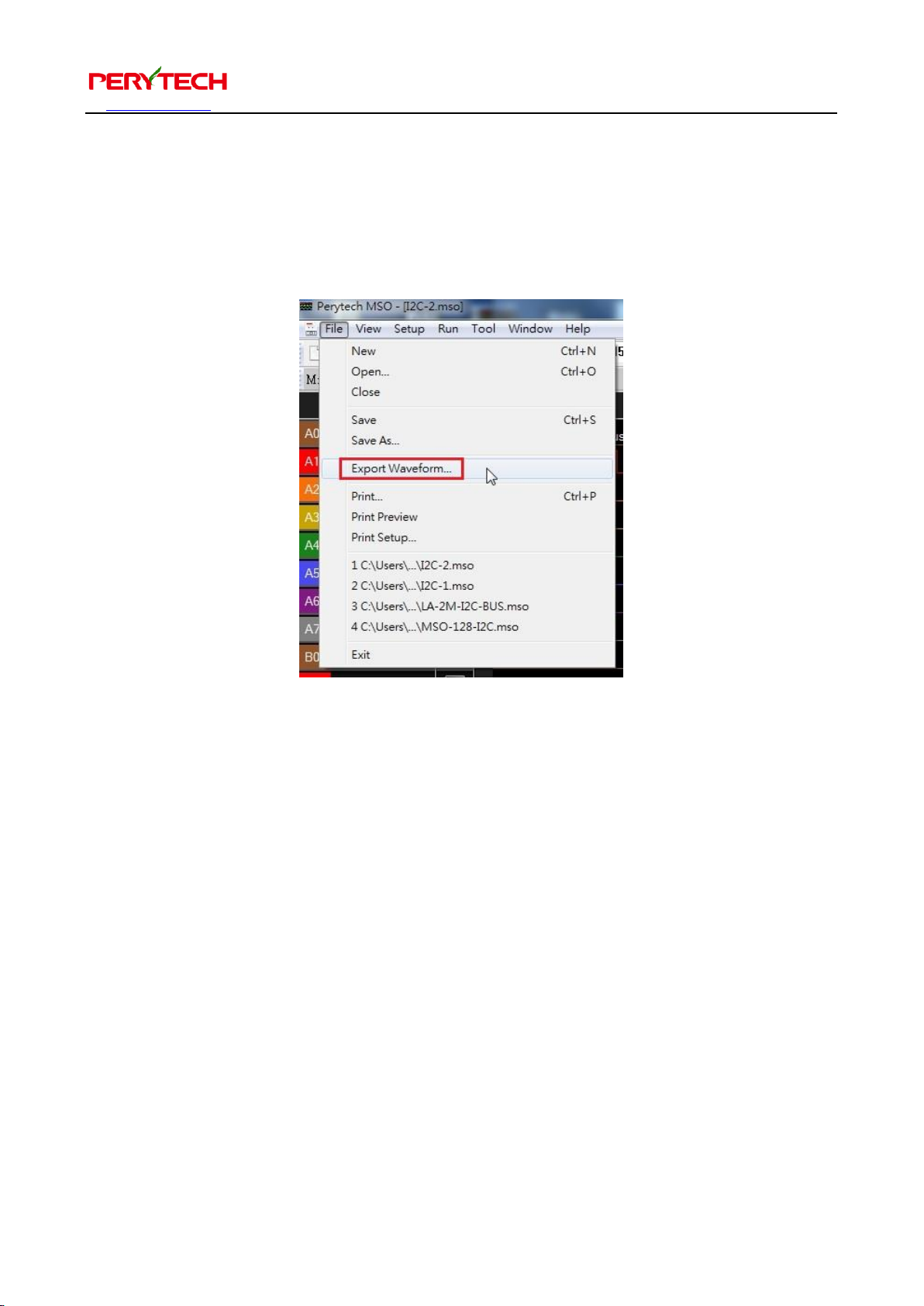
5.18. Data export function
The data export function can export the data as a text file. Open File → Export
Waveform, as shown below.
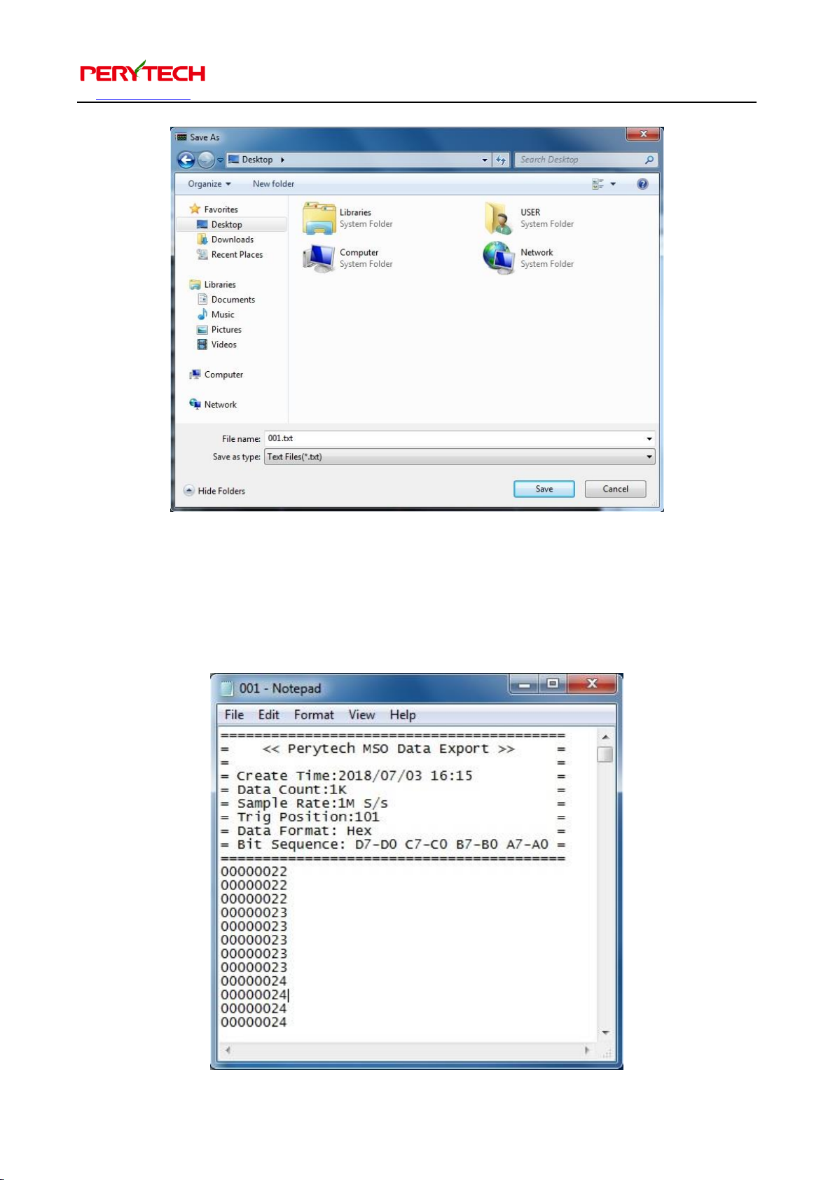
After implementing this function, the file save window will appear, as in the following
figure. You can choose the directory and file name you want to save under.
Page 32
沛瑞科技股份有限公司 TEL:886-2-2984-0000
www.perytech.com Peregrine Technology CO., LTD. FAX:886-2-2983-9999
31
The in the exported file is shown below. The start of the exported file has the file
export time (create time), memory depth (data count), and sampling rate. The data
content is in octal or hexadecimal numerals, representing 32 Bit data. From left to
right is the channels D7-D0, C7-C0, B7-B0, and A7-A0.
Page 33
沛瑞科技股份有限公司 TEL:886-2-2984-0000
www.perytech.com Peregrine Technology CO., LTD. FAX:886-2-2983-9999
32
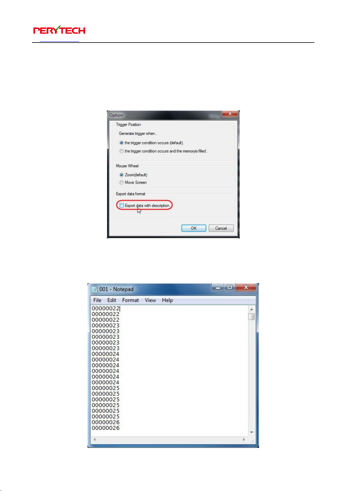
If you do not need the file starting information, you can change the setting in the
menu, under Tool → Option. In the Option window the default is selecting the “Export
data with description.” You can uncheck this selection, as shown below.
After unchecking the selection, the content of the exported file will only have data, as
shown below.
Page 34
沛瑞科技股份有限公司 TEL:886-2-2984-0000
www.perytech.com Peregrine Technology CO., LTD. FAX:886-2-2983-9999
33
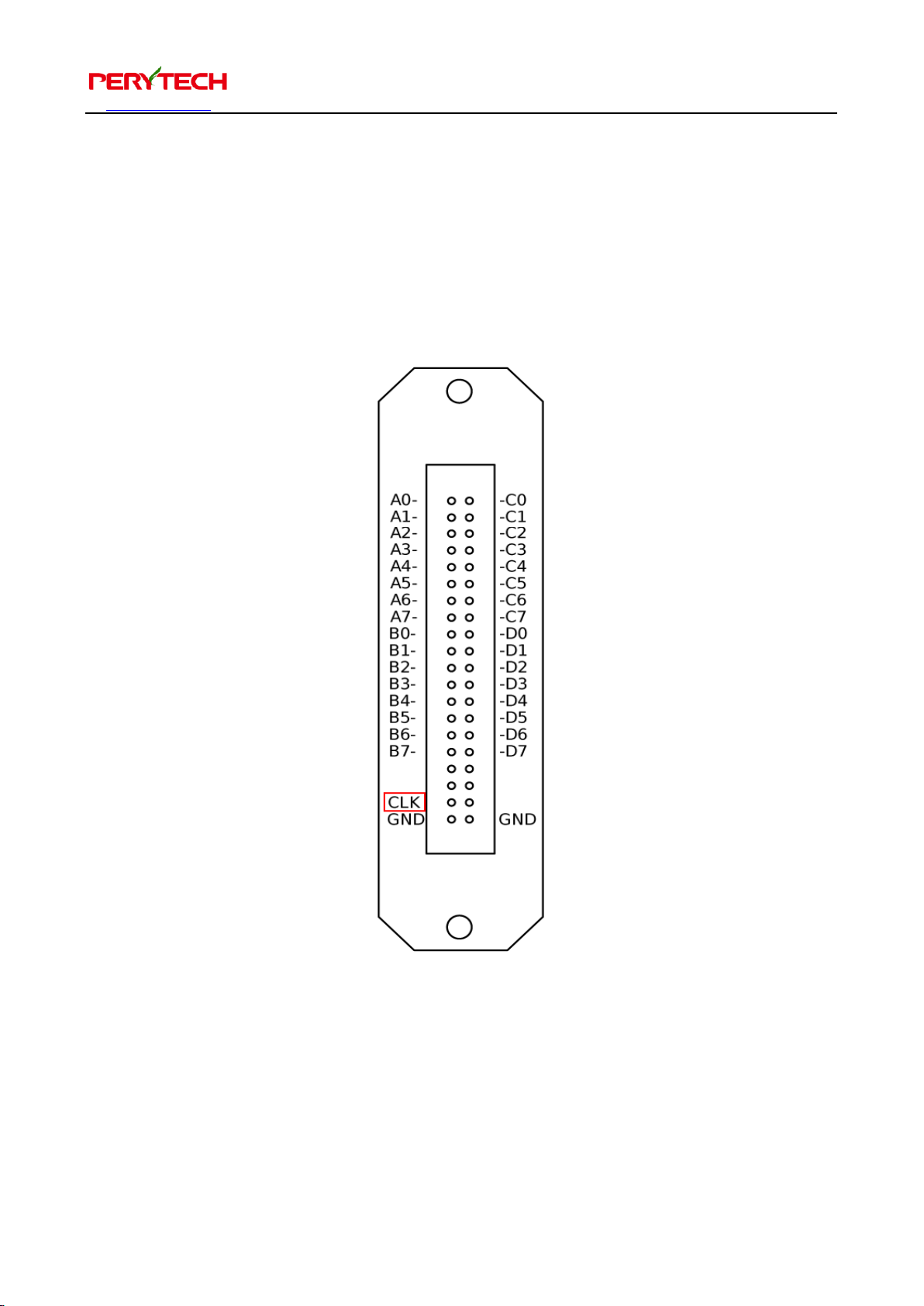
5.19. External clock input
Other than using the logic analyzer’s internal frequency, you can also use an external
input clock as the sampling frequency. There is a “CLK” input end on the logic analyzer
panel. For position, please reference the following red frame. The CLK is used for
inputting external clock.
Page 35
沛瑞科技股份有限公司 TEL:886-2-2984-0000
www.perytech.com Peregrine Technology CO., LTD. FAX:886-2-2983-9999
34
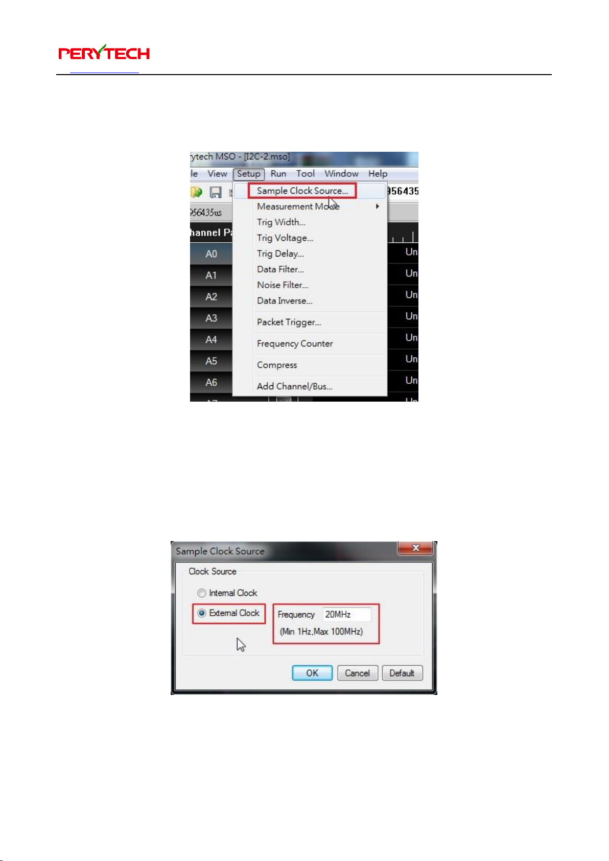
The software must be set to external clock. In the menu, choose Setup → Sample
Clock Source, as shown below.
After selecting this function, the Sample Clock Source window will appear, as shown
below. The Clock Source default is the “Internal Clock.” To change to input from an
external clock, please select “External Clock.” In the Frequency column, please input
the frequency of the external clock to make the time value accurate.
Page 36
沛瑞科技股份有限公司 TEL:886-2-2984-0000
www.perytech.com Peregrine Technology CO., LTD. FAX:886-2-2983-9999
35
5.20. Trigger width
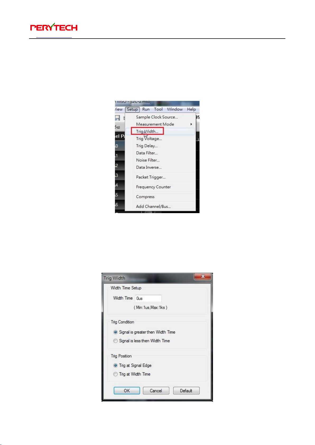
The logic analyzer can be set to trigger only when the signal width is greater than or
smaller than the set time. In the menu, choose Setup → Trig Width, as shown below.
After selecting, the Trig Width window will appear. This is used for setting the trigger
width parameters, as shown below. The “Width Time” column is used to set the signal
width. The “Trig Condition” is used to select greater than or less than the set time.
Page 37
沛瑞科技股份有限公司 TEL:886-2-2984-0000
www.perytech.com Peregrine Technology CO., LTD. FAX:886-2-2983-9999
36
The Trig Position area is used to set the position produced by the trigger. The “Trig at
Signal Edge” is when the trigger signal ends. The “Trig at Width Time” is when the
trigger condition is established.
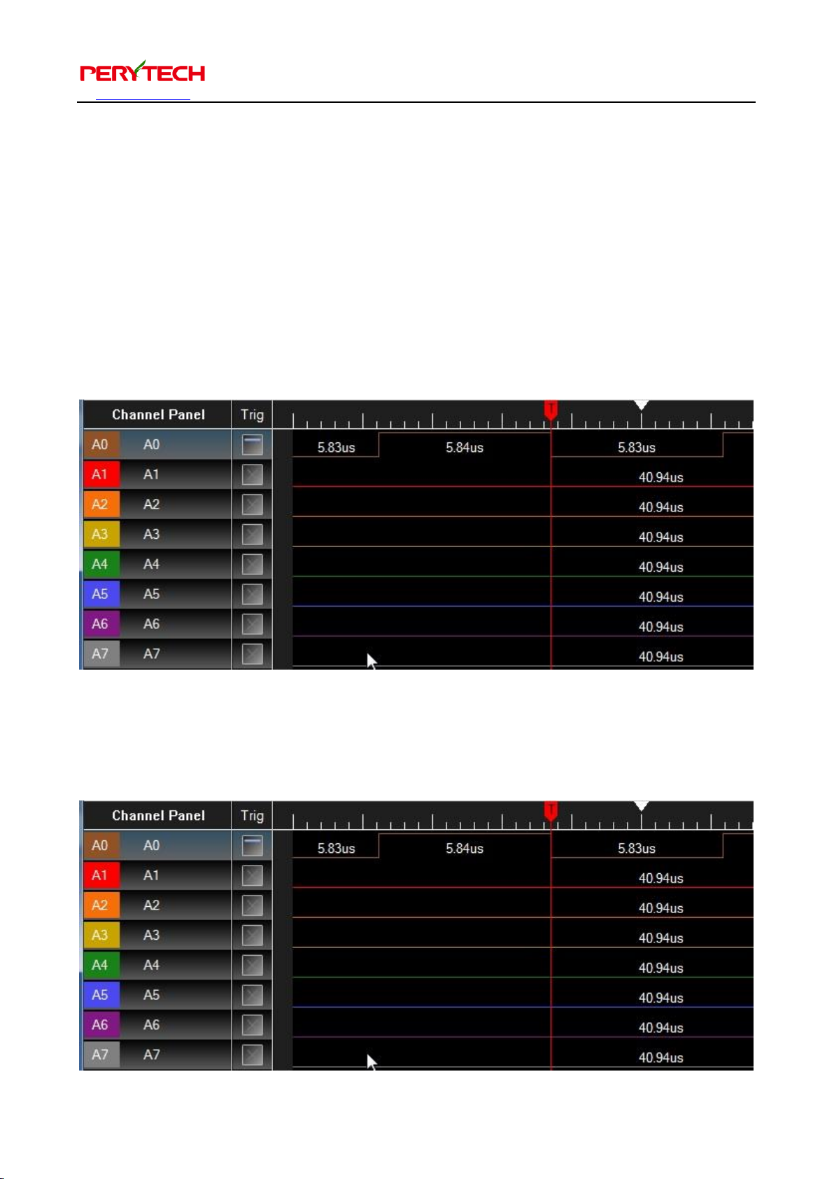
Here we use an actual example for the description. The trigger condition is set as
Channel A0 High, and triggers when the signal width is greater than 2us. The Trig
Position default is set as Trig at Signal Edge. The trigger point will appear at the
location where the High signal ends, as shown below.
If the Trig Position is changed to Trig at Width Time, then when the signal width
exceeds 2us, it will immediately trigger, as shown below.
Page 38
沛瑞科技股份有限公司 TEL:886-2-2984-0000
www.perytech.com Peregrine Technology CO., LTD. FAX:886-2-2983-9999
37
5.21. Set trigger voltage
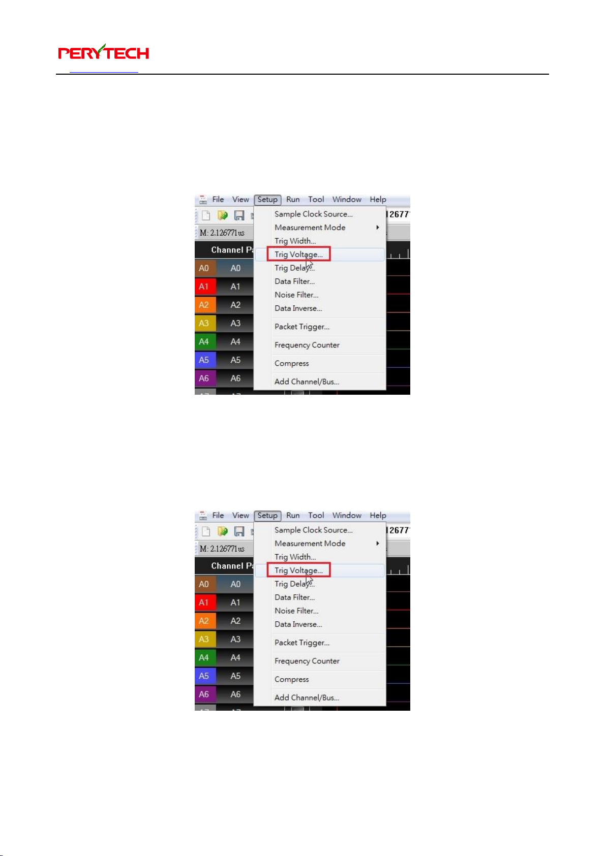
The logic analyzer default trigger voltage is 2.2V. When you need to adjust the trigger
voltage, go to the menu and select Setup → Trig Voltage, as shown below.
After selecting, the trigger voltage setting window will appear, as shown below. Input
the trigger voltage value and press OK. The trigger voltage setting scope is from -6.0V
- +6.0V.
Page 39
沛瑞科技股份有限公司 TEL:886-2-2984-0000
www.perytech.com Peregrine Technology CO., LTD. FAX:886-2-2983-9999
38
5.22. Delay trigger
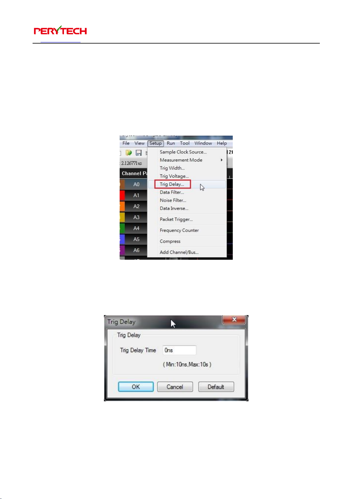
If you need to observe the waveform for a period of time after the trigger, you can use
the “Trig Delay” function to delay the trigger. The Trig Delay function is in the menu,
under Setup → Trig Delay, as shown below. The Trig Delay window will appear after
being selected.
The Trig Delay window is as shown below. The setup method is simple. Just directly
input the delay time and press OK.
Page 40
沛瑞科技股份有限公司 TEL:886-2-2984-0000
www.perytech.com Peregrine Technology CO., LTD. FAX:886-2-2983-9999
39
5.23. Data filter
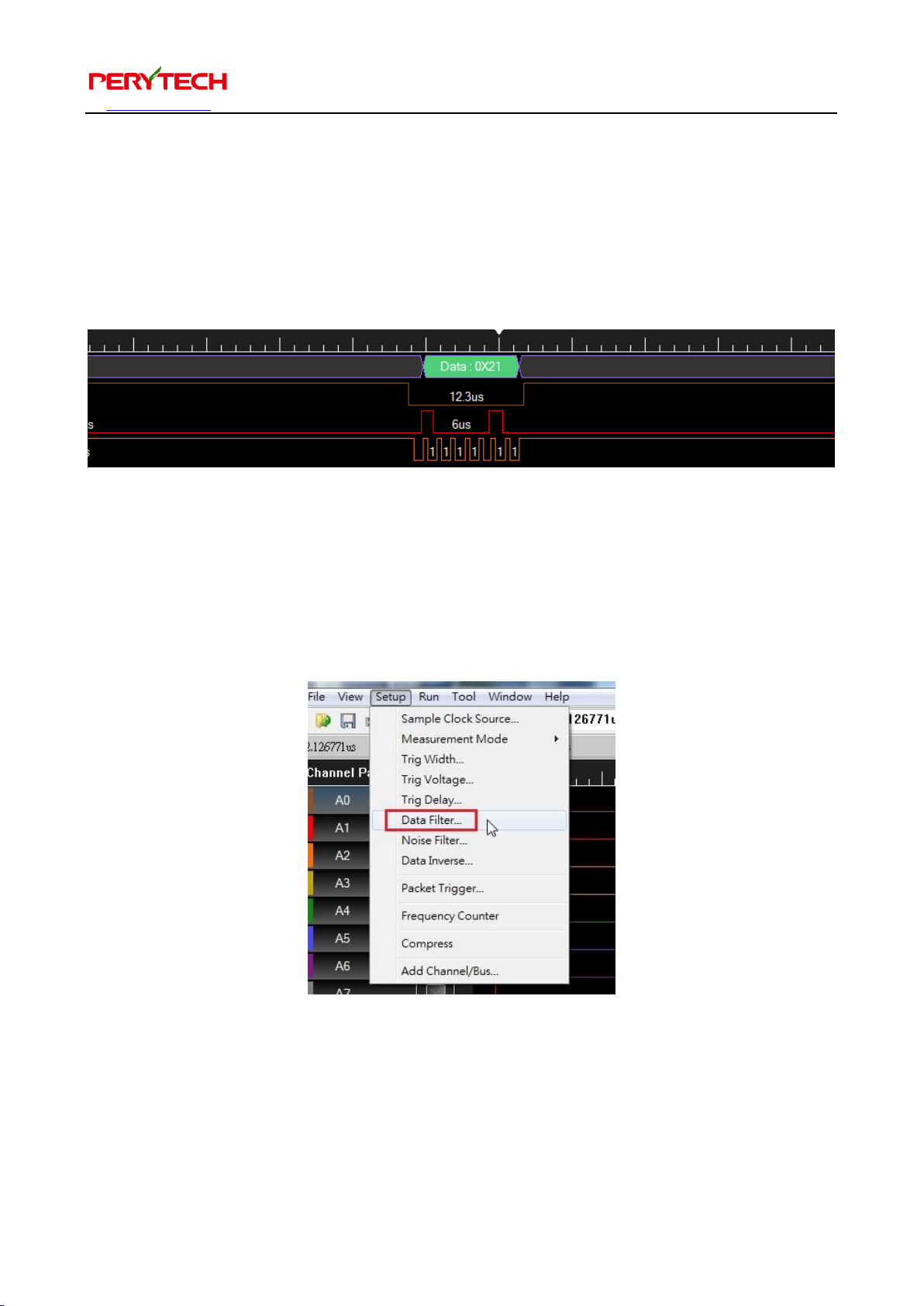
When there is a large amount of data and you only need a small part, you can use the
data filter function to filter out the required data. The following figure is a SPI signal.
Because the data interval is long, the screen will only show one piece of data.
Observation of this SPI signal shows that when the data is transmitted, the Enable
signal (brown) is in Low status. At this time we can use the Data Filter function to filter
out the signal that has been enabled as Low. The Data Filter function is in the menu,
under Setup → Data Filter, as shown below.
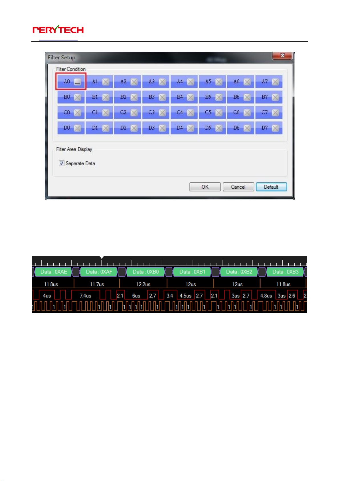
Set to extract data when the Enable signal (A0) is Low, as shown below.
Page 41
沛瑞科技股份有限公司 TEL:886-2-2984-0000
www.perytech.com Peregrine Technology CO., LTD. FAX:886-2-2983-9999
40
Waveform of the extracted signal after setting the filter is shown below. When Enable
is High, the data will be filter out, leaving data that has been enabled as Low.
“Separate Data” function will retain a piece of filtered data to be used as data
separation. This can facilitate data analysis. The default is open, but you can turn it off.
Page 42
沛瑞科技股份有限公司 TEL:886-2-2984-0000
www.perytech.com Peregrine Technology CO., LTD. FAX:886-2-2983-9999
41
5.24. Noise filter
Noise filter can be used in an environment with a lot of interference to filter out
unnecessary noise. The function is located in the menu under Setup → Noise Filter, as
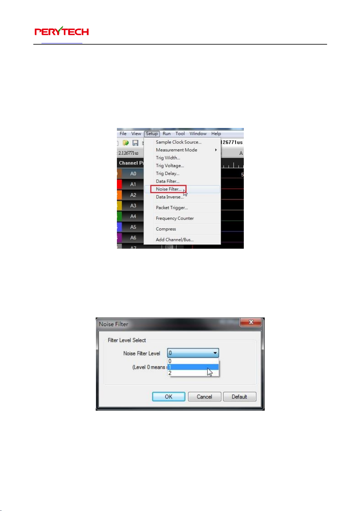
shown below.
The Noise Filter window is as shown below. You can use the pull-down menu to select
the noise filter level. The choices are 0, 1, or 2. The default is 0, which means that the
filter function is not in use.
Page 43
沛瑞科技股份有限公司 TEL:886-2-2984-0000
www.perytech.com Peregrine Technology CO., LTD. FAX:886-2-2983-9999
42
5.25. Data inverse function
Sometimes the data needs to be inversed, such as when measuring the RS-232 signal.
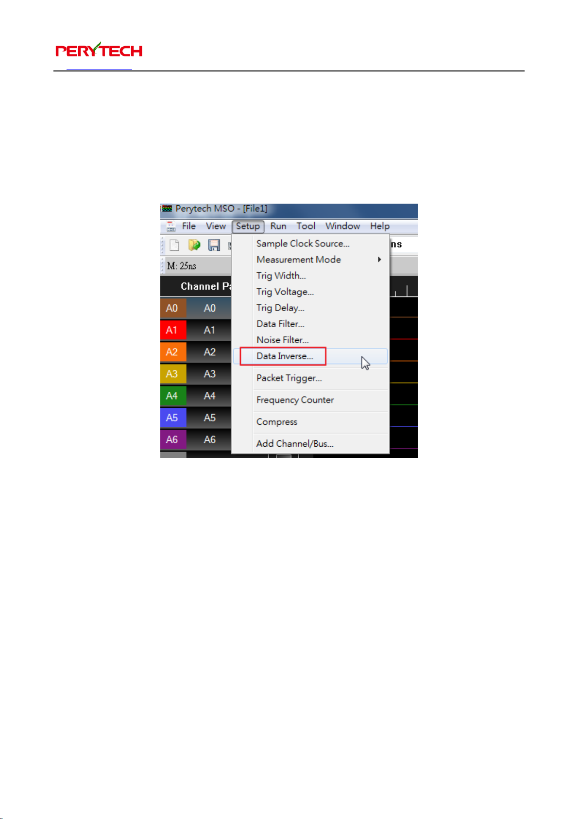
At this time, the “data inverse” function can be used. The data inverse function is in the
menu, under Setup → Data Inverse, as shown below.
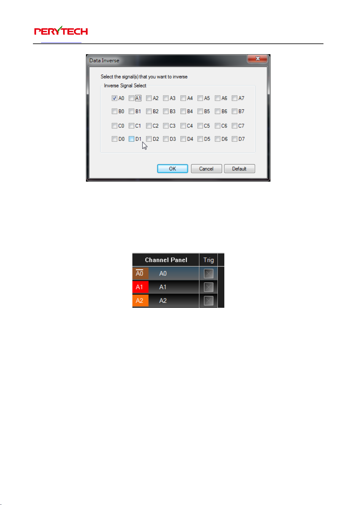
Data Inverse window is as follows. Here you can select the channels you wish to
inverse.
Page 44
沛瑞科技股份有限公司 TEL:886-2-2984-0000
www.perytech.com Peregrine Technology CO., LTD. FAX:886-2-2983-9999
43
Channels set as inverse will have a horizontal line on the channel panel. This indicates
that the data is inversed. The following figure is the A0 channel set to data inverse.
A0’s data will be changed from High to Low and from Low to High.
Page 45
沛瑞科技股份有限公司 TEL:886-2-2984-0000
www.perytech.com Peregrine Technology CO., LTD. FAX:886-2-2983-9999
44
5.26. Packet trigger function
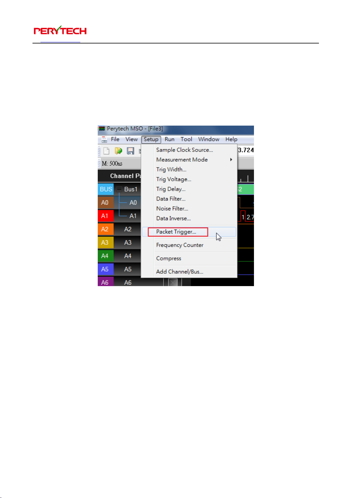
If you need to capture a specific bus packet you can use the “packet trigger” function.
The packet trigger function is in the menu, under Setup → Packet Trigger, as shown
below.
The principle behind the packet trigger is to analyze the extracted data to determine if
it contains the packet you need. If the data does not contain the packet, it will
continue to run until the designated packet appears.
Because packet trigger analyzes extracted data, you still need to set hardware trigger
to accurately extract data.
Page 46
沛瑞科技股份有限公司 TEL:886-2-2984-0000
www.perytech.com Peregrine Technology CO., LTD. FAX:886-2-2983-9999
45
5.27. Frequency counter function
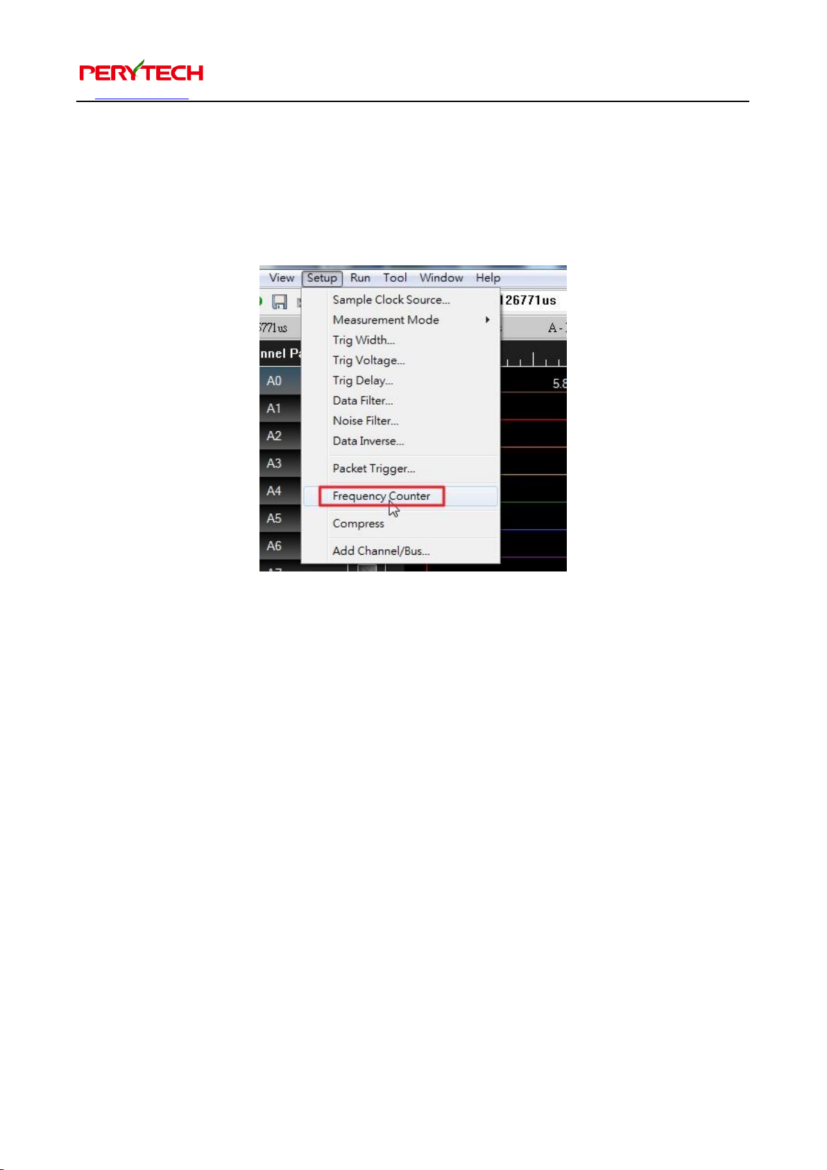
Frequency counter allows you to measure the signal frequency. The location is in the
menu, under Setup → Frequency Counter, as shown below.
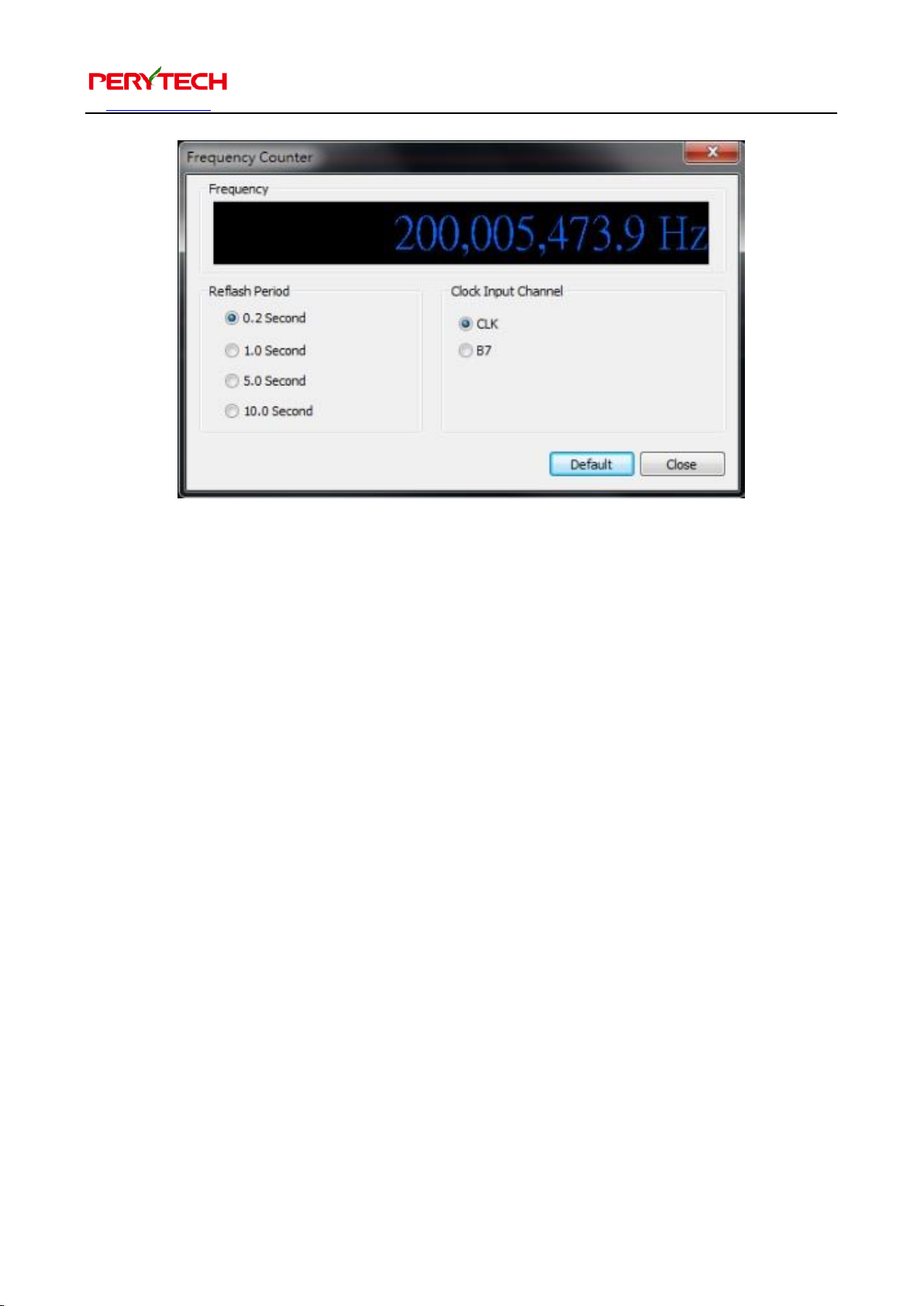
The maximum digit in the frequency counter function is 10 digits. The accuracy level
can reach 0.1Hz and the highest measured frequency is 200 Mhz. There are four
measuring cycles, 0.2, 1, 5, or 10 seconds. The higher the cycle is, the more precise the
measurement. There are two measurement channels that can be chosen as the
frequency counter input. The level of the CLK channel input resistance 1M Ω and
bandwidth 200 Mhz cannot be adjusted. The level of B7 channel input resistance 500
Ω and bandwidth 100MHz can be adjusted.
Page 47
沛瑞科技股份有限公司 TEL:886-2-2984-0000
www.perytech.com Peregrine Technology CO., LTD. FAX:886-2-2983-9999
46
5.28. Compression function
Perytech logic analyzer can support a maximum data compression of over one million
times, which can significantly improve your measurement time.
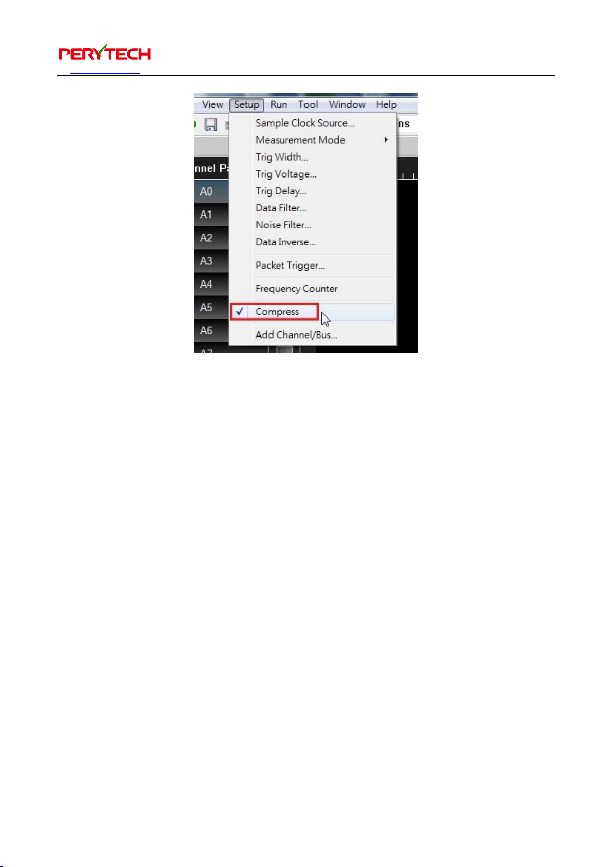
The compression function is easy to use. In the menu, choose Setup → Compress.
After selecting, a check mark will appear next to the “Compress,” as shown below. This
indicates that the compression mode has been enabled. In the compression mode, 16
channels can be used.
Page 48
沛瑞科技股份有限公司 TEL:886-2-2984-0000
www.perytech.com Peregrine Technology CO., LTD. FAX:886-2-2983-9999
47
Principle of the compression function: in normal situations, the logic analyzer will
store all sampled signal into the memory. When compression is enabled, the signal
content and time duration is only stored when the signal changes. Because in reality
the signal will not have change at each sampling point, the compression function can
generally significantly increase the measuring time period.
Page 49
沛瑞科技股份有限公司 TEL:886-2-2984-0000
www.perytech.com Peregrine Technology CO., LTD. FAX:886-2-2983-9999
48
6. Specification
Specification /
Model
PLA-1664
PLA-16128
PLA-32128
PLA-321M
PLA-322M
Channels
16
16
32
32
32
Memory
Depth(Per
Channel)
64k
128k
128k
1M
2M
Max.
Compression
Depth
64G
128G
128G
1T
2T
Max. Compression
Record Time (Sec)
320
640
640
5000
10000
Max Sample Rate
200MS/s
Max External Clock
Input Frequency
200MHz
Bandwidth
100MHz
Max Compression
Ratio
2^20 (More than 1 million)
Available
Channels for
Compression
16
Data Filter
Support filtering independently or with compression functions
Noise Filter
Support hardware glitch filter with 1 or 2 sampling width
Trig Condition
Rising Edge, Failing Edge, Either Edge, High, Low, None
Trig Width
Support trigger condition that signal is greater than or less than specific
Width Time
Trig Position
Adjustment
Trigger position can be adjusted for occupying 10% to 90% of memory,
and the default value is 50%
Trig Delay
Function
Support
Trig Voltage
Range
+6V ~ -6V
Trig Voltage
Resolution
0.1V
Page 50
沛瑞科技股份有限公司 TEL:886-2-2984-0000
www.perytech.com Peregrine Technology CO., LTD. FAX:886-2-2983-9999
49
Max Input Voltage
±30V
Bus Decode
I2C, SPI, UART, I2S, PS2, 1-Wire, USB 1.1, S/PDIF, SD, CAN Bus, Lin
Bus, 3-Wire, Microwire, SSI, Miller, Manchester, SM Bus, Modbus (be
on the increase)
Bus Upgrade
Always free
Bus Packet List
Support
Bus Export
Waveform
Support
Input Impedance
500KΩ / 10pF
OS Support
Windows XP / Vista / Windows 7 / Windows 8.1 (32 & 64) / Windows 10
(32 & 64)
Interface
USB 2.0
Dissipation Power
< 2.5W
Power
USB (DC 5V, 500mA)
Dimension
134 x 89 x 24 (mm)
Weight
220 g
 Loading...