

Page 1
POWER RELAY INSTALLATION INSTRUCTIONS
Maximizing Ignition Energy with a PerTronix Power Relay
Ignitor II and Ignitor III ignition systems require a full + 12V power connection between the ignition switch and
the positive coil terminal. Most AMC,Chrysler, and Ford vehicles are equipped with OE resistance wires or ballast
resistors. All pre-1974 (Non HEI) GM vehicles are equipped with OE resistance wire. To get the full benet of our
high performance ignition systems the primary resistance needs to be eliminated or bypassed. In most cases, adding
a PerTronix ignition power relay may be easier than cutting into the vehicles wiring harness and replacing wires.
PARTS INCLUDED WITH POWER RELAY KIT
• 30 Amp auto relay
• relay socket and harness
• 3 Amp 400 volt diode
• self tapping sheet metal screw
• male and female connectors
• battery ring terminal
• coil ring terminal
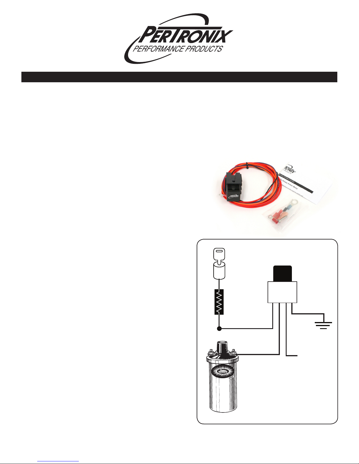
1. Determine the best location to mount the relay socket and
harness. Common mounting locations include the re wall
or inner fenderwell. Make sure the location you choose
enables the wires to be routed clear of headers, exhaust
manifolds, fan blades and belts. Also make sure each wire
will reach its destination.
2. Drill a small pilot hole in the desired location and use the
provided sheet metal screw to mount the socket.
3. Attach the short black ground wire to a good clean ground.
4. Disconnect the ignition switch wire from the coil positive
terminal. Use the provided male and female tab connectors to attach the ignition switch wire directly to the small
purple wire from the power relay.
5. Run the orange wire from the power relay to the coil positive terminal. Determine the proper wire length and cut the
wire to size. Attach the provided ring terminal. Attach the
orange wire to the positive coil terminal.
6. Run the large red wire to the battery positive terminal.
Determine the proper length and cut the wire to size. Attach
the large ring terminal. Fasten the large red wire to the battery positive post.
7. Insert the relay into the relay socket.
8. Test for proper operation of the circuit by starting the en-
gine and then turning ignition key o. If engine continues
to run after the key is turned o, remove the relay to stop
the engine and proceed to step 9 on the back. If the engine
stops running when key is turned o, your installation of
the ignition power relay is complete.
IGNITION
SWITCH
OEM BALLAST
RESISTOR OR
RESISTANCE WIRE
SMALL PURPLE
Coil
+ Terminal
ORANGE
POWER RELAY
BLACK
GROUND
LARGE RED
+ 12 VOLT
FROM BATTERY
0000-008770 07/12
Page 2
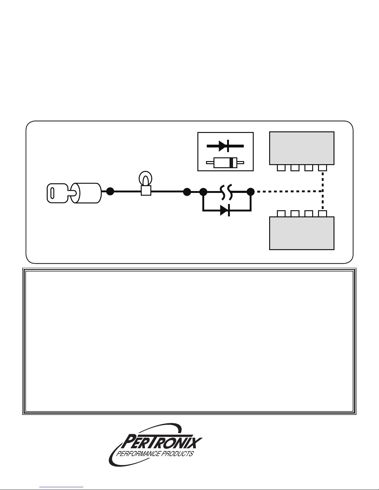
Isolation Diode Installation
9. Most pre-1974 GM vehicles equipped with Delcotron alternators with external regulator and most Ford vehicles with
Autolite / Motorcraft alternators with external regulator will require isolation diode installation. The isolation diode
prevents current from the regulator owing back to the ignition power relay when the key is turned o.
10. Locate the terminal on voltage regulator that is connected to charge indicator light. This is terminal I on most Ford
regulators and terminal 4 on most GM regulators. A top view of the regulator is shown in diagram below to help with
terminal identication. Break the wire going to this terminal and solder the diode to the wire ends. Observe diode
polarity indicated by a “band” on the diode. Wrap diode and wires with electrical tape. Make sure diode or bare wires
cannot touch any metal surface.
11. Verify proper operation of charging circuit and ignition system. If charge indicator light , does not light up when key
is turned on before engine is started, diode was probably installed backwards.
DIODE POLARITY
GM
REGULATOR
2F 3 4
IGNITION
SWITCH
CHARGE
LIGHT
ADD DIODE
A ISF
FORD
REGULATOR
LIMITED WARRANTY
PerTronix, Inc. warrants to the original Purchaser of its power relay that the product shall be free from defects in material and workmanship (normal wear and tear excluded) for a period of 12 months from the date of purchase.
If within the period of the foregoing warranty PerTronix finds, after inspection, that the product or any component thereof is defective,
PerTronix will, at its option, repair such products or component or replace them with identical or similar parts PROVIDED that within such
period Purchaser:
Promptly notifies PerTronix, in writing, of such defects. Delivers the defective product or component to PerTronix (Attn: Warranty)
with proof of purchase date; and Has installed and used the product in a normal and proper manner, consistent with PerTronix printed
instructions
THE FOREGOING LIMITED WARRANTY IS EXCLUSIVE AND IN LIEU OF ALL OTHER WARRANTIES, WHETHER
EXPRESS OR IMPLIED, INCLUDING ANY IMPLIED WARRANTY OF MERCHANTABILITY OR FITNESS FOR A PARTICULAR
PURPOSE.
THE FURNISHING OF A REPAIR OR REPLACEMENT COMPONENT OR COMPONENTS SHALL CONSTITUTE THE
SOLE REMEDY OF PURCHASER AND THE SOLE LIABILITY OF PerTronix WHETHER ON WARRANTY, CONTRACT OR
FOR NEGLIGENCE, AND IN NO EVENT WILL PerTronix BE LIABLE FOR MONEY DAMAGES WHETHER DIRECT OR
CONSEQUENTIAL.
440 East Arrow Highway
San Dimas, CA 91773
909-599-5955
www.pertronix.com
 Loading...