

Page 1
ADVANCE LIMITERS
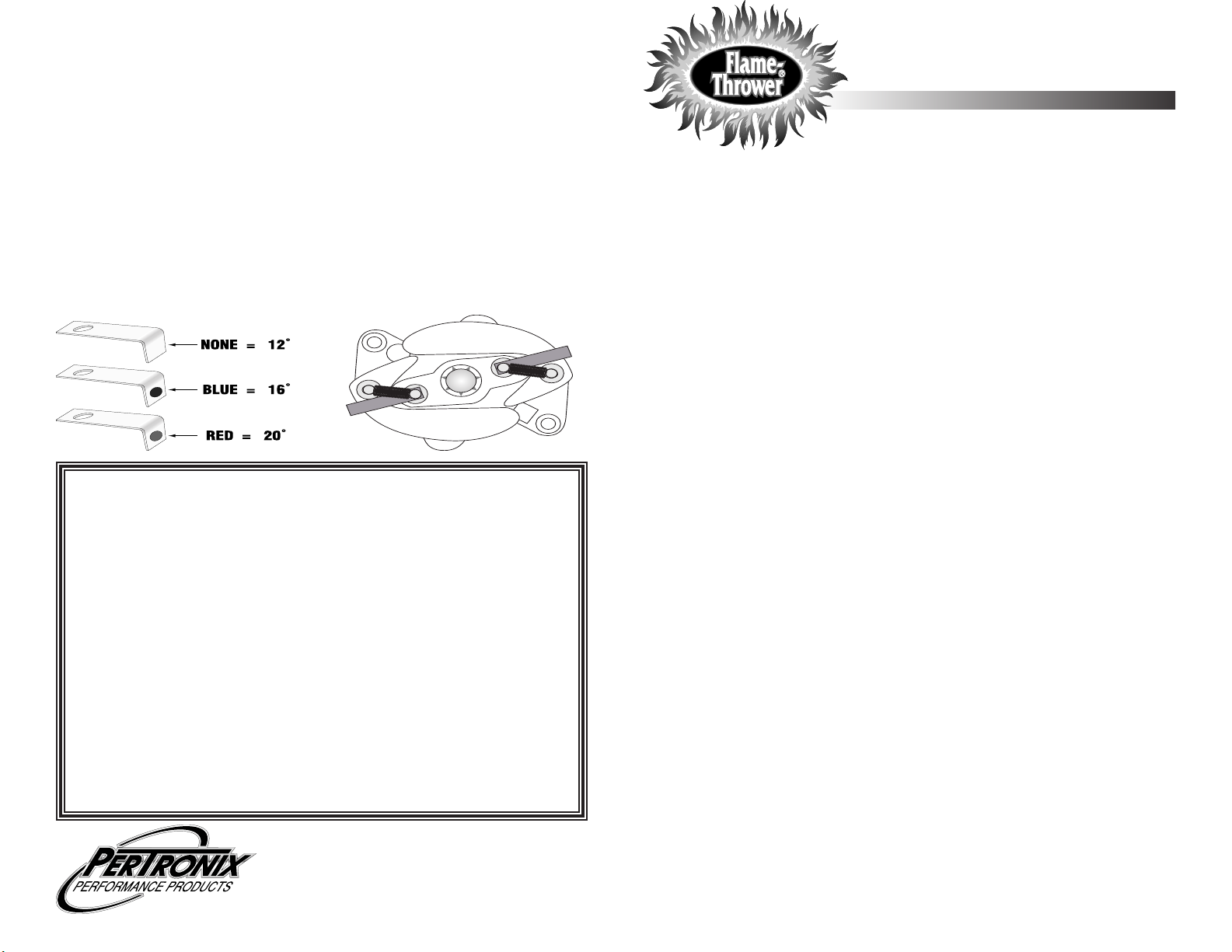
The Flame-Thrower billet distributor comes with three different sets of advance limiters. These allow the maximum mechanical advance to be
limited to 20, 16 or 12 degrees (Crankshaft Degrees).
Choose the desired advance limit from the chart below. 1.
Remove the distributor cap and rotor. 2.
Remove the advance springs.3.
Install one advance limiter on each inner advance pin. (See Figure 1)4.
Reinstall the advance springs.5.
Reinstall the rotor and cap.6.
The advance limiters can be mixed resulting in unique variations of the original 7.
advance curve. When combined with mixed advance springs and limiters the
mechanical advance can have a maximum of 78 different advance curves.
MAXIMUM MECHANICAL ADVANCE WITH LIMITERS INSTALLED
Crank Shaft Degrees
LIMITED WARRANTY
PerTronix, Inc. warrants to the original Purchaser of its Flame-Thrower billet distributor
that the product shall be free from defects in material and workmanship (normal wear and
tear excluded) for a period of 12 months mechanical distributor and 30 months Ignitor II
from the date of purchase.
If within the period of the foregoing warranty PerTronix finds, after inspection, that
the product or any component thereof is defective, PerTronix will, at its option, repair such
products or component or replace them with identical or similar parts PROVIDED that
within such period Purchaser:
1. Promptly notifies PerTronix, in writing, of such defects.
2. Delivers the defective product or component to
PerTronix (Attn: Warranty) with proof of purchase date; and
3. Has installed and used the product in a normal and proper
manner, consistent with PerTronix printed instructions
THE FOREGOING LIMITED WARRANTY IS EXCLUSIVE AND IN LIEU OF ALL
OTHER WARRANTIES, WHETHER EXPRESS OR IMPLIED, INCLUDING ANY IMPLIED
WARRANTY OF MERCHANTABILITY OR FITNESS FOR A
PARTICULAR PURPOSE.
THE FURNISHING OF A REPAIR OR REPLACEMENT COMPONENT
OR COMPONENTS SHALL CONSTITUTE THE SOLE REMEDY OF PURCHASER AND
THE SOLE LIABILITY OF PerTronix WHETHER ON WARRANTY, CONTRACT OR FOR
NEGLIGENCE, AND IN NO EVENT WILL PerTronix BE LIABLE FOR MONEY DAMAGES
WHETHER DIRECT OR CONSEQUENTIAL.
440 East Arrow Highway
San Dimas, CA 91773
909-599-5955
www.pertronix.com
BILLET SLIP COLLAR DISTRIBUTOR
INSTALLATION INSTRUCTIONS
GENERAL INFORMATION
IMPORTANT:1. Read all instructions before starting installation.
Flame-Thrower Billet distributors come with hardened steel distributor gears 2.
which should not be used in applications with a billet camshaft. Consult camshaft
manufacturer for distributor gear compatibility.
Solid core spark plug wires 3. MUST NOT be used.
DISTRIBUTOR REMOVAL
Crank the engine until it is positioned at top dead center on a compression stroke. 1.
The timing indicator should point to 0.
Remove the distributor cap, and make sure that the rotor is pointing towards the 2.
first cylinder in the firing order.
Disconnect the battery negative (-) cable.3.
Disconnect all wires and hoses attached to the distributor. 4.
Remove the distributor hold down.5.
Remove the distributor by lifting up on the distributor housing while slightly turning 6.
the rotor.
Check the distributor gear for signs of excess wear, or potential problems.7.
ADJUSTING THE SLIP COLLAR
Billet Slip Collar Distributor is set to standard deck height at the factory.
Slip Collar adjustment procedure:
Insert the distributor (gasket installed) into the engine until it bottoms out against 1.
the oil pump drive.
Slide the slip collar down into position, raise the distributor 0.010" - 0.030", and 2.
tighten it.
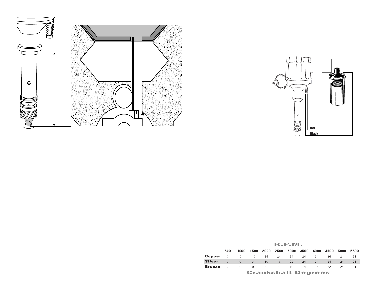
Checking the Oil Pump to Distributor Shaft Overlap
Oil pump drive and distributor shaft overlap is very important. The tang of the distribu-
tor should t into the slot of the oil pump drive by at least 1/4".
Oil pump drive and distributor shaft overlap procedure:
Measure the distance between the bottom of ange and the tip of the distributor 1.
tang (Figure 1).
Measure the distance from the intake manifold to the top of the oil pump drive 2.
intermediate shaft (Figure 1).
Subtract both measurements. The difference is the overlap. If there the clearance 3.
is too much or not enough, a different oil pump drive intermediate shaft is required.
Continue Next Pain
0019-00872204-08
Page 2
-!.)&/,$
%.').%
",/#+
/),05-0
$2)6%
-%!352%
FIGURE 1
+
-
T o Ignition
-%!352%
"%47%%.
"/44/-/&
&,!.'%!.$
4!.'
FIGURE 2
CHECKING GEAR MESH
This procedure is recommended to insure proper gear mesh between the cam gear
and the distributor gear.
Procedure: Coat the distributor gear with moly grease and install the distributor. Next,
crank the engine over several times. Before removing the distributor, ensure that the
rotor position is line up with the original removal mark. Remove distributor and inspect
the gear pattern shown on the grease. The proper mesh will leave an even pattern in
the middle of the gear. Adjust the slip collar if needed to correct the gear mesh.
DISTRIBUTOR INSTALLATION
Remove the Flame-Thrower billet distributor cap.1.
Install the distributor gasket over the gear, and up to the distributor collar. Use a 2.
small amount of gasket adhesive to help hold the gasket in place.
Lubricate the distributor gear and distributor shaft with clean engine oil. 3.
Turn the shaft so that when the distributor is placed into the engine, the rotor posi-4.
tion matches that of the original distributor. As the distributor drops down, the rotor
will turn slightly as it engages with the camshaft gear. Adjust for this rotation by
turning the rotor a few degrees prior to the gear engagement. Several attempts
may be necessary to achieve the proper rotor position. The distributor collar should
sit completely flat on the intake manifold or block.
Place the distributor cap onto the housing. 5.
Turn the housing so that the terminal, that represents the first cylinder in the firing 6.
order, lines up with the rotor.
Install the distributor hold down and tighten the hold down bolt slightly. Once the 7.
ignition timing is adjusted the hold down bolt should be tightened completely.
Tighten the cap into place and install the spark plug wires in the proper firing 8.
order.
DISTRIBUTOR INSTALLATION CONT.
Locate the vacuum hose that was previously attached to the vacuum advance can-9.
ister. This hose should originate at a ported vacuum source. For Vacuum advance
distributors: Temporarily plug the end of this hose to allow proper timing. After setting initial timing the hose will be unplugged and attached to the vacuum advance
on the distributor. For Non-vacuum advance distributors: remove the vacuum hose
and plug the vacuum port.
WIRING
The Flame-Thrower billet distributor can be used in conjunction with
most ignition coils rated at 0.45
ohms or greater. For optimum
performance purchase and install
a Flame-Thrower II or HV E-Core
high performance coil.
Many vehicles came equipped 1.
with ballast resistors or resistance wires. To achieve optimum performance we recommended removal of these components.
Determine the proper wire 2.
length, and attach the provided
terminals. (Use a designated wire
crimping tool to achieve an adequate connection)
Attach the Red wire to the coil positive terminal or a 12-volt ignition source.3.
Attach the Black wire to the coil negative terminal. 4.
Check to insure correct polarity and that all connections are tight.5.
Reconnect the battery negative cable.6.
FINAL ADJUSTMENTS
Start the engine and set the initial timing.1.
Tighten the distributor hold down.2.
For vacuum advance distributors, connect the vacuum hose to the vacuum 3.
advance canister.
MECHANICAL ADVANCE ADJUSTMENTS
To adjust the mechanical advance curve, elect the appropriate springs from the 1.
chart below. The Flame-Thrower billet distributor is factory equipped with the
silver springs.
Remove the cap and rotor.2.
Remove the existing springs and install the desired springs.3.
Reinstall the rotor and cap. 4.
 Loading...