

Page 1
Corporate Office: PerTronix Inc. 440 E. Arrow Highway, San Dimas, California 91773 * Phone 909.599.5955 * FAX 909.599.6424 * www.dougsheaders.com
HEADER INSTALLATION INSTRUCTIONS
D6680
96-04 MUSTANG, 4.6L, 2V, SOHC
PerTronix©
to realize the full potential of our good fit, please read and understand these instructions completely prior to starting work.
CHECK TO MAKE SURE YOU RECEIVED THE PROPER PARTS FOR YOUR APPLICATION. THE HEADER NUMBER WILL
BE STAMPED ON THE ENGINE FLANGE. IF YOU ARE UNSURE YOU HAVE RECEIVED THE PROPER PARTS CALL
BEFORE YOU START WORK.
BE SURE TO WORK SAFE! WHENEVER YOU WORK UNDER THE VEHICLE BE SURE THAT IT IS LOCATED ON LEVEL,
SOLID GROUND AND IS SUPPORTED BY ADEQUATE SAFETY STANDS!
REMEMBER: HOT ASPHALT WILL NOT SUPPORT MOST JACK STANDS!
Many factors affect the installation of headers, some of which are broken or aftermarket motor mounts, accidents that impact the
configuration of the frame, and/or the installation of different engines or aftermarket cylinder heads. Most installations require
some welding. If you are uncomfortable with welding operations, we recommend that you contact a professional exhaust
system specialist to install your new headers.
Attention Customers breaking in new engines: Due to the extreme heat generated during the break-in process, the
appearance of the ceramic coating may be altered in certain areas. The protection characteristics and thermal barrier properties
of the coating is never compromised. It is recommended that a cast iron manifold or old set of headers be used for this process.
Notice: The coating of these headers can be marred or scratched during installation. If the header needs to be returned and is
damaged, you will be charged for recoat.
thanks you for choosing
DOUG’S HEADERS
, the best fitting, highest quality header on the market. In order
DISASSEMBLY / ASSEMBLY
DISASSEMBLY (LEFT SIDE)
1. Disconnect the negative battery cable from the battery.
2. Disconnect the E.G.R. tube from the throttle body.
3. Remove the cold air tube from the air cleaner and throttle body.
4. On Cobra models, remove the upper tower support bracing.
5. Remove the bolt from the oil dipstick tube.
6. Raise the car and support it with axle stands.
7. On hard top models, remove the A-arm brace.
8. Disconnect the four (4) O2 sensor wires from the H-pipe.
9. Remove the front two (2) sensors from the H-pipe and mark each one (left/right).
Part No. 0110-003064 Page 1 of 5 Rev 1 3-5-13 DSL
Page 2
10. Remove the H-pipe assembly.
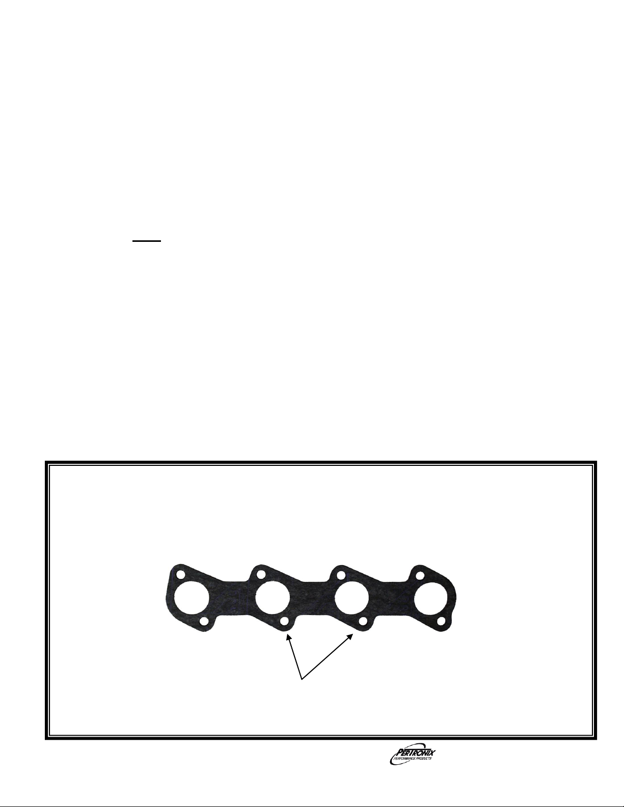
Install these two header bolts with the gasket.
Front
DISASSEMBLY (LEFT SIDE) Continued
11. Disconnect the E.G.R. tube from the rear of the manifold (left side).
12. Disconnect the steering shaft. Note: a disconnected steering shaft must not be rotated
more than 360 degrees.
13. Remove the engine mount nut (left side).
14. Raise the engine (left side).
15. Remove the manifold (left side) and manifold studs.
ASSEMBLY (LEFT SIDE)
1. Apply a THIN film of Ultra Copper Hi-Temp Sensor-Safe Silicone Sealer to both sides of
the header gasket.
2. Install the header bolts shown in DIAGRAM 1 with the header gasket. Note: Header
flange bolts holes are slotted for the ease of bolt installation and are not intended to be
installed before the header is inserted into the engine bay. Only the bolts specified in
the installation procedure should be installed before the header is inserted into the
engine bay.
3. With the left side of the engine raised, insert the left side header into the engine bay.
4. Slip the header down over the top bolts installed in step (15). Install and snug the
remaining bolts. Tighten all the header bolts.
5. Lower the left side of the engine onto the engine mounts. Install the mount nut and
tighten.
6. Install the E.G.R. tube to the header.
7. Install the steering shaft and tighten the bolt.
8. Install the left O2 sensor into the left side header and reconnect the harness.
DIAGRAM 1
Part No. 0110-003064 Page 2 of 5 Rev 1 3-5-13 DSL
Page 3

DISASSEMBLY (RIGHT SIDE)
Install this header bolt with the gasket.
Front
1. Remove the engine mount nut (right side).
2. Raise the engine (right side).
3. Remove the starter. Note: the upper starter bolt is more accessible after lifting the engine
(right side).
4. Remove the manifold (right side).
ASSEMBLY (RIGHT SIDE)
1. Apply a THIN film of Ultra Copper Hi-Temp Sensor-Safe Silicone Sealer to both sides of
the header gasket.
2. Install the header bolt as shown in DIAGRAM 2 with the header gasket. Note: Header
flange bolts holes are slotted for the ease of bolt installation and are not intended to be
installed before the header is inserted into the engine bay. Only the bolt specified in the
installation procedure should be installed before the header is inserted into the engine
bay.
3. With the right side of the engine raised, insert the right side header into the engine bay.
4. Slip the header up under the bolt installed in step (2). Install the back lower header bolt to
hold the header in place. Install the remaining header bolts. Tighten all the header
bolts.
5. Install the starter motor and tighten the bolts. Install the wires on the starter and tighten.
6. Lower the engine (right side). Install engine mount nut and tighten.
DIAGRAM 2
Part No. 0110-003064 Page 3 of 5 Rev 1 3-5-13 DSL
Page 4

TURNOUTS AND H-PIPE INSTALLATION
1. Bolt the right and left side turnouts to the headers with the collector gaskets and snug the
bolts. (Note: The left side turnout is the shorter one, the right side turnout is the longer
one with an O2 sensor fitting in it).
2. In this step, the H-pipe is modified so it can be welded directly to the new turnouts. Cut
the left and right head pipes off the old H-pipe at the weld at the front end of the leading
catalytic converters, as shown in PHOTO 1.
3. Install the H-pipe. Hold the front end of the H-pipe up to the turnouts installed in step (1).
Snug the bolts at the rear of the H-pipe to the exhaust system. Check the right and left
turnouts for a close fit for welding. Note: The right and left turnouts should just overlap
the leading edge of the catalytic converters.
4. Weld as much of the right and left turnouts as you can reach with the H-Pipe installed.
Remove the partially welded H-pipe/turnout assembly and complete the welding.
5. Install the right O2 sensor in the right turnout. Install the newly welded H-pipe assembly
and tighten the bolts and reconnect the remaining three (3) O2 sensors to their harness.
6. On hard top models, install the A-arm brace.
7. Install cold air tube to the throttle body and the air cleaner.
8. Reconnect E.G.R. tube to the throttle body.
9. Install the dipstick tube bolt.
10. On Cobra models, reinstall the upper tower support bracing.
11. Inspect the steering shaft for proper installation.
12. Ensure that all electrical connections that were disconnected are properly reconnected.
13. Ensure all electrical wires are secured so as not to come into contact with the headers.
14. Reconnect the battery.
PHOTO 1
Left Side Right Side
Part No. 0110-003064 Page 4 of 5 Rev 1 3-5-13 DSL
Page 5

START THE ENGINE
Start the engine and allow it to warm up to operating temperature. Check for any unusual
noises or exhaust leaks. If every thing is OK, stop the engine and tighten all bolts while
the engine is still warm.
NOTE: Check the bolts periodically to make sure they have not loosened. Re-tighten
after the first 500 miles and then again at 1000 miles
IMPORTANT CHECK LIST
Be sure that all brake lines and fuel lines are clear of headers and/or connector
pipes.
All spark plug wires, battery cables, or other electrical components should be clear
of headers and/or connector pipes.
If dipstick tube was removed, make sure it is installed properly and that the
dipstick has been replaced.
Double-check the tightness of all bolts including brackets and accessories.
PARTS LIST
Qty Description
1 Left side header
1 Right side header
1 Left turnout (short)
1 Right turnout (long, w/ O2 sensor fitting)
2 Header gasket
2 Turnout gasket
16 Bolt, header, flanged, M8-1.25 x 30
22 Lock washer, 3/8”
6 Hex head cap screw, 3/8”-16 x 1-1/4”
6 Nut, hex, 3/8”-16
1 Sticker (C.A.R.B., E.O., D-57-19)
Part No. 0110-003064 Page 5 of 5 Rev 1 3-5-13 DSL
 Loading...