

Page 1
Corporate Office: PerTronix Inc. 440 E. Arrow Highway, San Dimas, California 91773 * Phone 909.599.5955 * FAX 909.599.6424 * www.dougsheaders.com
HEADER INSTALLATION INSTRUCTIONS
D6614Y-1, D6614Y-1SP
1988 –1993 FORD “F” SERIES PICK-UP 2 & 4 WD 460 V8
PART NUMBER: D6614Y-1 & D6614Y-1SP
PerTronix
order to realize the full potential of our good fit, please read and understand these instructions completely prior to starting work.
CHECK TO MAKE SURE YOU RECEIVED THE PROPER PARTS FOR YOUR APPLICATION. THE HEADER NUMBER WILL
BE STAMPED ON THE ENGINE FLANGE. IF YOU ARE UNSURE YOU HAVE RECEIVED THE PROPER PARTS CALL
BEFORE YOU START WORK.
BE SURE TO WORK SAFE! WHENEVER YOU WORK UNDER THE VEHICLE BE SURE THAT IT IS LOCATED ON LEVEL,
SOLID GROUND AND IS SUPPORTED BY ADEQUATE SAFETY STANDS!
REMEMBER: HOT ASPHALT WILL NOT SUPPORT MOST JACK STANDS!
Many factors affect the installation of headers, some of which are broken or aftermarket motor mounts, accidents that impact the
configuration of the frame, and/or the installation of different engines or aftermarket cylinder heads. Most installations require
some welding. If you are uncomfortable with welding operations, we recommend that you contact a professional exhaust
system specialist to install your new headers.
Attention Customers breaking in new engines: Due to the extreme heat generated during the break-in process, the
appearance of the ceramic coating may be altered in certain areas. The protection characteristics and thermal barrier properties
of the coating is never compromised. It is recommended that a cast iron manifold or old set of headers be used for this process.
Notice: The coating of these headers can be marred or scratched during installation. If the header needs to be returned and is
damaged, you will be charged for recoat.
©
thanks you for choosing
DOUG’S HEADERS
, the best fitting, highest quality header on the market. In
DISASSEMBLY
1. Disconnect the negative battery cable from the battery.
2. Remove the air inlet hose from the throttle body to the air cleaner.
3. If a car lift is not available, raise the vehicle 2 feet or higher and support it with
adequate safety stands. Make sure the vehicle is on a flat solid surface and is stable.
4. Apply penetrating oil to all nuts and bolts to be removed. Allow adequate time for the
penetrating oil to do its work (multiple applications may be required on higher mileage
vehicles).
5. The removal of the front tires and inner fender panels makes the removal of the
exhaust manifolds and installation of the headers much easier, but is not required to
complete the job.
6. Unbolt the connector pipe from the exhaust manifolds.
7. Make note of the location and arrangement of the spark plug wires and carefully
remove them. Use a twisting motion while pulling away from the plug. Pull the boot
and not the wire.
8. Remove the spark plugs.
Part No. 0110-003032 Page 1 of 3 REV1 11-19-13 DSL
Page 2

9. Loosen the EGR tube using a 31mm wrench on the nut at the end of the tube; do not let
the fitting in the exhaust manifold turn during this operation.
10. If your vehicle is equipped with air injection remove the hoses at the rear of the exhaust
manifolds and loosen, but do not remove, the bolts that hold the injection tube brackets
at the rear of the heads and intake manifold.
11. Unbolt and remove the exhaust manifolds. This operation can be accomplished from
above the engine compartment.
12. Replace the spark plugs finger tight so debris will not get into the cylinders while
cleaning the head surface. We recommend the use of a gasket scraper, wire brush,
and sanding block to adequately clean the surface.
13. After cleaning is complete remove the spark plugs again.
14. Remove the engine oil dipstick and tube assembly.
15. Disconnect the oxygen sensor wires. Take care during this operation so as not to
damage the wire or plug. The wire disconnects at the wire loom, not at the sensor.
16. Remove the oxygen sensors.
17. On the driver side, remove the brake line shield.
18. Remove the nuts that hold the connector pipe to the front of the catalytic converter and
remove the connector pipe.
ASSEMBLY
1. Apply a THIN film of Ultra Copper Hi-Temp Sensor-Safe Silicone Sealer the each side
of the header gaskets around each port and stick the gaskets to each header. Check to
make sure that the gaskets match up to the header flange; these gaskets can be put on
backwards, which will cause leakage. You can use masking tape to help hold the
gaskets to the headers.
2. Apply a small amount of anti-seize to the threads of the header bolts.
3. Apply a small amount of anti-seize to the threads of the EGR nut.
4. Install the driver side header from the underside of the vehicle and start the EGR tube
nut about 3 to 4 threads and install the header bolts and lock washers, but do not
tighten them at this time.
5. If your vehicle is equipped with air injection install the air injection tube and tighten.
6. Tighten all of the header bolts to 35 ft. lbs.
7. Tighten the EGR tube.
8. Install the engine oil dipstick tube and dipstick.
9. Install the connector pipe assembly and new cat inlet gasket onto the studs on the front
of the catalytic converter, start the nuts, but leave them very loose.
10. Attach the connector pipe to the driver side header using the metal o-ring gasket, bolts,
lock washers and nuts supplied. Do not tighten at this point.
11. Install the passenger side header with gasket attached from under the vehicle and
install the supplied bolts with lock washers, but do not tighten.
12. If your vehicle has air injection, install and tighten the air injection tube utilizing the
bolts, nuts and gaskets supplied and tighten the air injection tube brackets on the rear
of the heads and intake manifold.
13. Attach the connector pipe to the passenger side header using the metal o-ring (donut)
gasket and the bolts supplied.
14. Adjust the connector pipe for best alignment and tighten all connections and clamp.
Check all the previously installed bolts to make sure that they are all tight.
Part No. 0110-003032 Page 2 of 3 REV1 11-19-13 DSL
Page 3
15. Apply a small amount of anti-seize to the threads of the oxygen sensor and install and
tighten it. Connect the wire and route the wire away from the exhaust piping, but allow
enough slack to allow for exhaust system movement.
16. Install the spark plugs and connect the wires to the proper plug. If the spark plugs have
a lot of miles on them, now would be a good time to replace them. When you install the
spark plugs, apply a small amount of anti-seize to the threads.
17. Install the appropriate connector pipe on the appropriate side of the vehicle and attach
them to the headers using the gaskets and hardware provided.
18. If you removed the inner fender panels and front tires; replace the panels and tires and
be sure to torque the lug nuts.
19. Connect the throttle body to air cleaner hose.
20. Connect the battery cable.
21. Check over the installation to make sure that all wires, lines, hoses, etc are connected
and have adequate clearance to protect them from the heat generated by the exhaust
system.
START THE ENGINE
Start the engine and allow it to warm up to operating temperature. Check for any unusual noises or exhaust leaks.
If every thing is OK, stop the engine and tighten all bolts while the engine is still warm.
NOTE: Check the bolts periodically to make sure they have not loosened. Re-tighten after the first 500 miles and
then again at 1000 miles.
IMPORTANT CHECK LIST
Be sure that all brake lines and fuel lines are clear of headers and/or connector pipes.
All spark plug wires, battery cables, or other electrical components should be clear of headers
and/or connector pipes.
If dipstick tube was removed, make sure it is installed properly and that the dipstick has been
replaced.
Double-check the tightness of all bolts including brackets and accessories.
PARTS LIST
Qty. Description
1 Right side header
1 Left side header
1 Connector pipe
1 Left side header gasket
1 Right side header gasket
2 Metal donut gasket
1 Catalytic converter inlet gasket
2 Air injection tube gasket (for D-6614Y-1-SP
part number only)
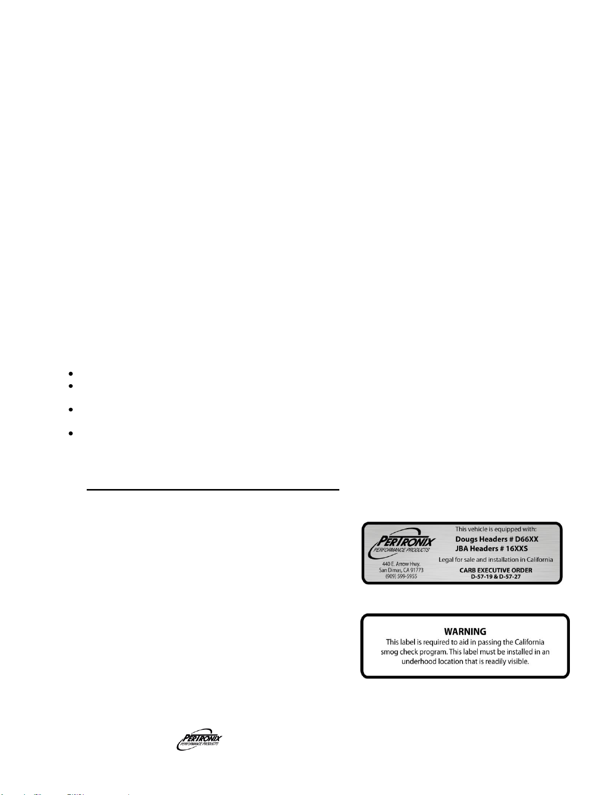
1 Decal:
1 Sticker, C.A.R.B., E.O., D-57-19
1 Hardware kit:
16 3/8”-16 x 1 ¼” header bolts
6 3/8”-16 x 2 ¼” hex bolts
6 3/8”-16 hex nuts
22 3/8” lock-washers
DOUG’S HEADERS
Part No. 0110-003032 Page 3 of 3 REV1 11-19-13 DSL
 Loading...