

Page 1
Corporate Office: PerTronix Inc. 440 E. Arrow Highway, San Dimas, California 91773 * Phone 909.599.5955 * FAX 909.599.6424 * www.dougsheaders.com
HEADER INSTALLATION INSTRUCTIONS
D3386
APPLICATION
1988-1995 4 W/D GM Pick-Up 5.7L V8
PART NUMBER: D3386
PerTronix
realize the full potential of our good fit, please read and understand these instructions completely prior to starting work.
CHECK TO MAKE SURE YOU RECEIVED THE PROPER PARTS FOR YOUR APPLICATION. THE HEADER NUMBER WILL BE
STAMPED ON THE ENGINE FLANGE. IF YOU ARE UNSURE YOU HAVE RECEIVED THE PROPER PARTS CALL BEFORE
YOU START WORK.
BE SURE TO WORK SAFE! WHENEVER YOU WORK UNDER THE VEHICLE BE SURE THAT IT IS LOCATED ON LEVEL,
SOLID GROUND AND IS SUPPORTED BY ADEQUATE SAFETY STANDS!
REMEMBER: HOT ASPHALT WILL NOT SUPPORT MOST JACK STANDS!
Many factors affect the installation of headers, some of which are broken or aftermarket motor mounts, accidents that impact the
configuration of the frame, and/or the installation of different engines or aftermarket cylinder heads. Most installations require some
welding. If you are uncomfortable with welding operations, we recommend that you contact a professional exhaust system
specialist to install your new headers.
Attention Customers breaking in new engines: Due to the extreme heat generated during the break-in process, the appearance
of the ceramic coating may be altered in certain areas. The protection characteristics and thermal barrier properties of the coating is
never compromised. It is recommended that a cast iron manifold or old set of headers be used for this process.
Notice: The coating of these headers can be marred or scratched during installation. If the header needs to be returned and is
damaged, you will be charged for recoat.
©
thanks you for choosing
DOUG’S HEADERS
, the best fitting, highest quality header on the market. In order to
DISASSEMBLY
1. Disconnect the negative battery cable from the battery.
2. If a car lift is not available, raise the vehicle 2 feet or higher and support it with adequate safety
stands. Make sure the vehicle is on a flat solid surface and is stable.
3. Apply penetrating oil to all nuts and bolts to be removed.
4. Remove the alternator bracket.
1- See Page 3, Figure 1. If your vehicle has this style alternator support bracket you will need to
cut as shown prior to removal for ease of removal. Make the “FIRST CUT” in the vehicle with
a Sawzall® (or equivalent). Remove the right hand portion and make the “SECOND CUT”
with the bracket held securely in a vise.
5. Remove the air filter and its ducting and cover the air intake to prevent any foreign objects from
entering the engine.
6. Remove the spark plug heat shields. Note: These are not reinstalled.
7. Note the spark plug wire locations and remove them from the spark plugs. Use a twisting motion
while pulling the spark plug boot off of the spark plug. Be very careful not to damage the spark
plug boot and do not pull on the wire itself.
8. Remove the spark plugs.
Part No. 0110-003021 Page 1 of 5 rev 1 8-17-2011DSL
Page 2

9. Remove the spark plug wire looms and dipstick tube bracket bolt, and unplug any temperature
sensor wiring that is associated with the spark plug wires.
10. Unplug O2 sensor wires and remove O2 sensors, use care so as to not damage the wire or the
sensor. We recommend the removal of all the O2 sensors as any welding operations may damage
them.
11. Remove the catalytic converter clamp and stock head pipes and connector pipe. (Note: The use of
heat and/or force may be necessary to separate the system at this point. Do not cut this junction
apart. It is illegal to modify the front of the catalytic converter).
12. Remove the head pipes from the manifolds.
13. Remove the engine oil dipstick tube bolt and remove the tube by using a twisting motion while
gently pulling up on the tube.
14. Remove the exhaust manifolds and pull the manifolds out through the top of the engine
compartment.
15. Clean the mounting surface on the cylinder head. Make sure that you remove all traces of carbon
and foreign material to provide a smooth clean sealing surface for the headers.
ASSEMBLY
1. Apply a THIN film of Ultra Copper Hi-Temp Sensor-Safe Silicone Sealer to the header side of the
supplied gaskets and glue them to the headers. Masking tape can be used to help stick the
gaskets to the manifolds.
2. Apply a THIN film of Ultra Copper Hi-Temp Sensor-Safe Silicone Sealer to the engine side of the
gasket and install the driver side header into the vehicle. Use the original bolt (NOT A SUPPLIED
HEADER BOLT) in the front bolt hole. Use a supplied 3/8” lock-washer and the 1” spacer on this
bolt as well. Install the supplied 3/8”-16 X 1 ¼” header bolts and 3/8” lock-washers in the
remaining 5 bolt holes. Tighten to 35 ft/lbs.
3. Apply a small amount of anti-seize to the header bolts and install the driver side header utilizing
the star washers with the header bolts. Tighten the bolts at this time.
4. Reinstall the alternator bracket and weld the two pieces back together where ther “First Cut” was
made (as shown on Page 3, Fig. 1).
5. Apply a THIN film of Ultra Copper Hi-Temp Sensor-Safe Silicone Sealer to the engine side of the
gasket and install the passenger side header from below the vehicle using the supplied 3/8”-16 x 1
¼” header bolts and 3/8” lock-washer. Note: Do not install the bolt at the dipstick tube bracket at
this time.
6. Install the dipstick tube in the block and install the header bolt into the bracket, but do not tighten
at this time.
7. Tighten all the header bolts, including the dipstick tube bolt, evenly on both sides of the engine to a
final torque of 35 ft. lbs.
8. Install the connector pipes by sliding them onto the front of the catalytic converters and bolt them
to the headers utilizing the two 2 ½” dome gaskets and 3/8” bolts, nuts and lock washers provided.
Do not tighten the bolts at this time.
9. Install the clamps on the connecter pipes and tighten the bolts at the header connections.
10. Slip connector pipe into catalytic converter and install clamp.
11. Install the O2 Sensors and connect the wires
12. Install the spark plugs and attach the appropriate wire to the spark plug and reattach the spark
plug wire looms.
13. Remove any covering that was placed over the intake and install the air filter and air inlet ducting.
START THE ENGINE
Start the engine and allow it to warm up to operating temperature. Check for any unusual noises or exhaust leaks. If
everything is OK, stop the engine and tighten all bolts while the engine is still warm.
NOTE: Check the bolts periodically to make sure they have not loosened. Re-tighten after the first 500 miles and then
again at 1000 miles.
Part No. 0110-003021 Page 2 of 5 rev 1 8-17-2011DSL
Page 3
IMPORTANT CHECK LIST
Be sure that all brake lines and fuel lines are clear of headers and/or connector pipes.
Check front drive shaft clearance.
All spark plug wires, battery cables, or other electrical components should be clear of headers and/or
connector pipes.
If dipstick tube was removed, make sure it is installed properly and that the dipstick has been
replaced.
Double-check the tightness of all bolts including brackets and accessories.
TOOLS / LUBRICANTS / SEALERS REQUIRED LIST
Description
Heating torch
Mig welder
Cut-off saw
Sawzall® (or equivalent) w/metal cutting 6” blade
3/8”, 7/16”, 9/16”, ½”, ¾”, 7/8”, 10mm and 13mm wrenches
9/16” Line wrench (flare nut)
5/16”, 7/17”, ½” and 9/16” sockets
3/8” & 7/16” and15mm deep sockets
5/8” spark plug socket
Ratchet and extensions
Pliers and an adjustable jaw wrench
Torque wrench
Rust penetrant
High temp 700° F “sensor-safe” silicon sealer:
PARTS LIST
Qty. Description
1 Right side header
1 Left side header
1 Right side connector pipe
1 Left side connector pipe
1 Left side header gasket
1 Right side header gasket
2 2 ½” dome gaskets
1 2 ½” clamp
1 3” clamp
1 3/8” spacer, 1” long, mild steel
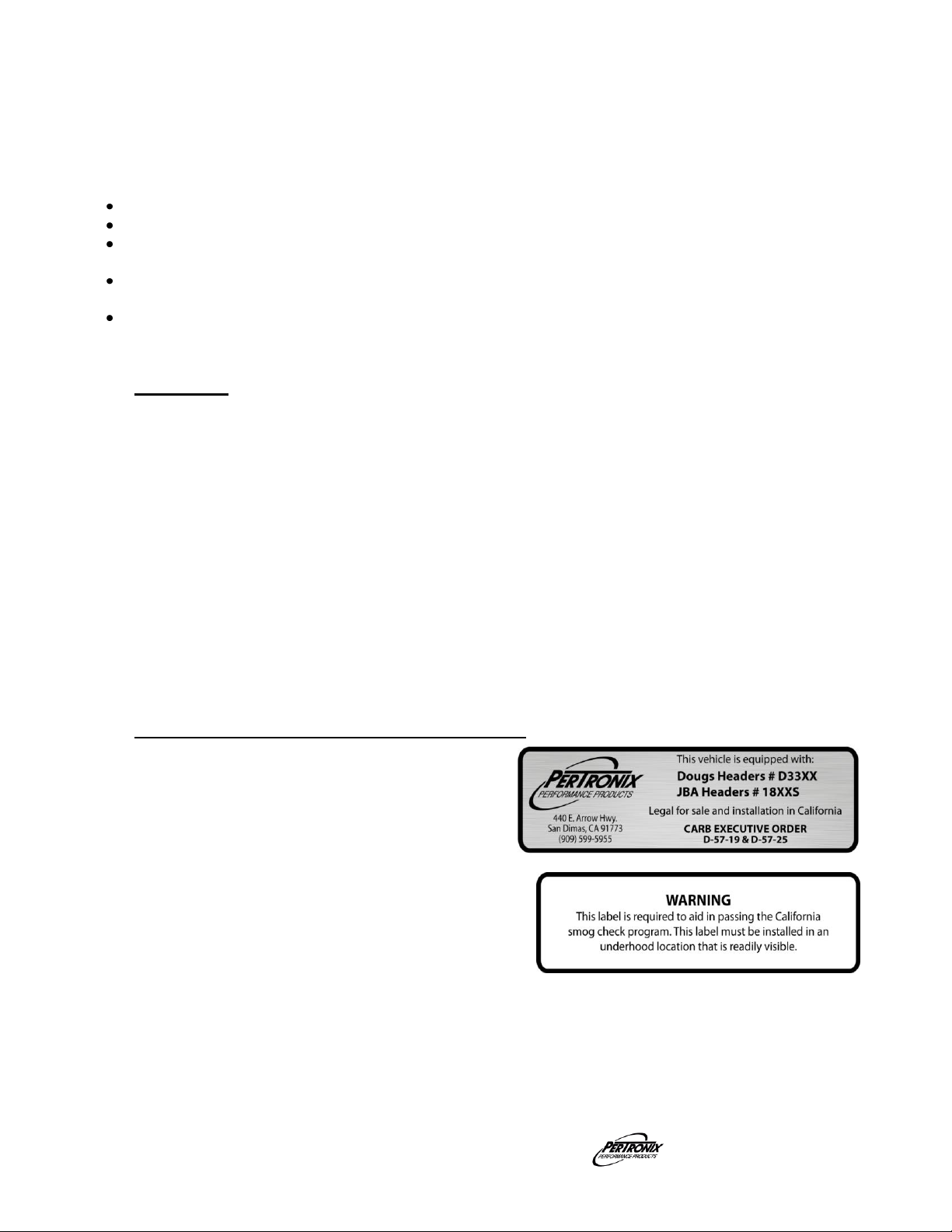
1 Decal:
1 Sticker, C.A.R.B., E.O., D-57-19
1 Hardware kit:
12 3/8”-16 x 1 ¼” header bolts
6 3/8”-16 x 1 ¼” hex bolts
6 3/8”-16 hex nuts
18 3/8” lock-washers
Part No. 0110-003021 Page 3 of 5 rev 1 8-17-2011DSL
DOUG’S HEADERS
Page 4
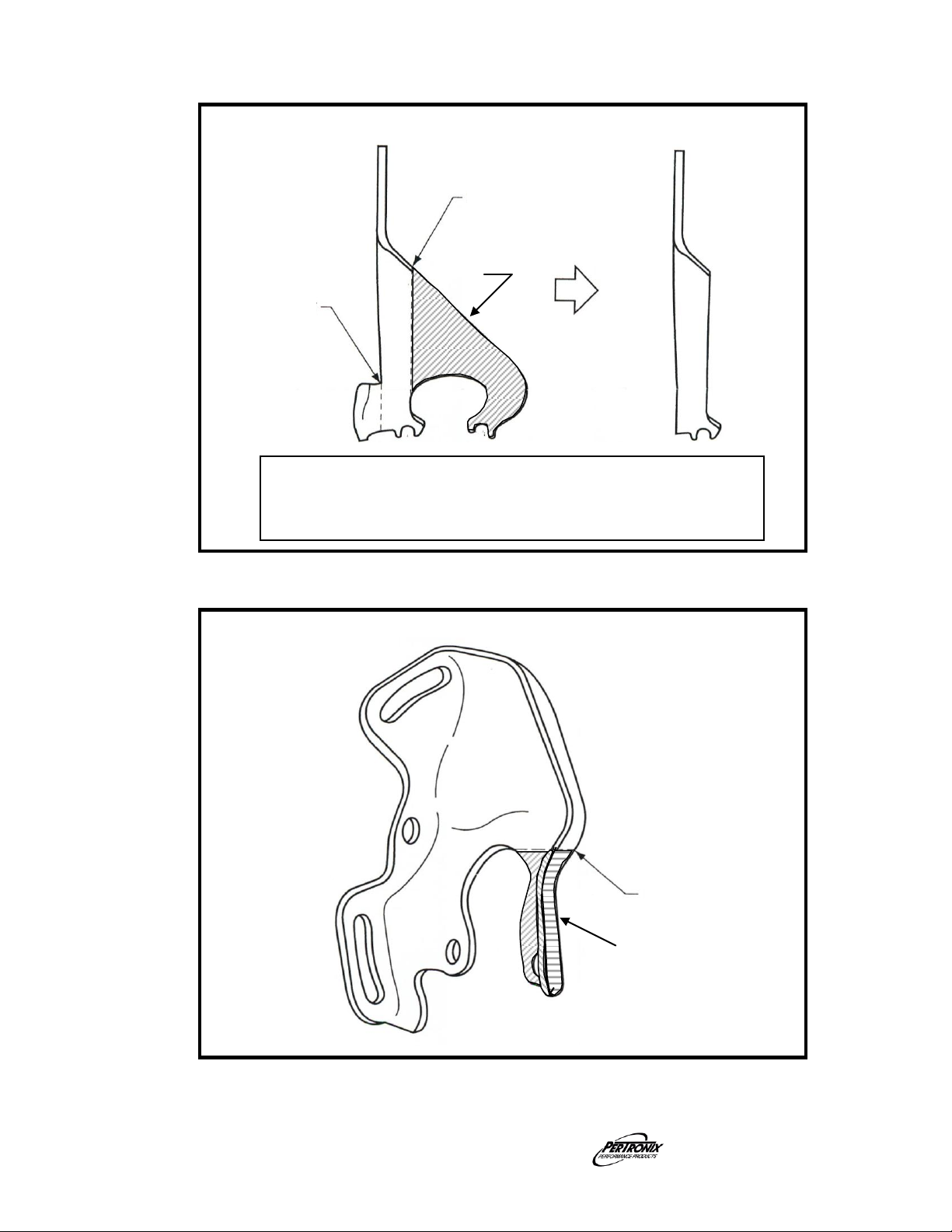
Figure 1
ALTERNATOR SUPPORT BRACKET MODIFICATION
SECOND CUT
FIRST CUT
(Disassembly
Step 2)
WELD
(Assembly
Step 7)
Discard
- Make the “FIRST CUT” in the vehicle with a Sawzall
®
(or equivalent).
- Remove the right hand portion, place securely in a vice and make
the “SECOND CUT”.
- Discard the shaded area.
AIR CONDITIONING BRACKET MODIFICATION
CUT HERE
Discard
Figure 2
Part No. 0110-003021 Page 4 of 5 rev 1 8-17-2011DSL
 Loading...