

Page 1
Corporate Office: PerTronix Inc. 440 E. Arrow Highway, San Dimas, California 91773 * Phone 909.599.5955 * FAX 909.599.6424 * www.patriotexhaust.com
HEADER INSTALLATION INSTRUCTIONS
Part # D3342
APPLICATION
1968-1987 Chevrolet/GMC ½, ¾ & 1 Ton 2&4 WD Pickup
396-502 Big Block Chevrolet
PerTronix
realize the full potential of our good fit, please read and understand these instructions completely prior to starting work.
CHECK TO MAKE SURE YOU RECEIVED THE PROPER PARTS FOR YOUR APPLICATION. THE HEADER NUMBER WILL BE
STAMPED ON THE ENGINE FLANGE. IF YOU ARE UNSURE YOU HAVE RECEIVED THE PROPER PARTS CALL BEFORE
YOU START WORK.
BE SURE TO WORK SAFE! WHENEVER YOU WORK UNDER THE VEHICLE BE SURE THAT IT IS LOCATED ON LEVEL,
SOLID GROUND AND IS SUPPORTED BY ADEQUATE SAFETY STANDS!
REMEMBER: HOT ASPHALT WILL NOT SUPPORT MOST JACK STANDS!
Many factors affect the installation of headers, some of which are broken or aftermarket motor mounts, accidents that impact the
configuration of the frame, and/or the installation of different engines or aftermarket cylinder heads. Most installations require some
welding. If you are uncomfortable with welding operations, we recommend that you contact a professional exhaust system
specialist to install your new headers.
Attention Customers breaking in new engines: Due to the extreme heat generated during the break-in process, the appearance
of the ceramic coating may be altered in certain areas. The protection characteristics and thermal barrier properties of the coating is
never compromised. It is recommended that a cast iron manifold or old set of headers be used for this process.
Notice: The coating of these headers can be marred or scratched during installation. If the header needs to be returned and is
damaged, you will be charged for recoat.
©
thanks you for choosing
DOUG’S HEADERS
, the best fitting, highest quality header on the market. In order to
DISASSEMBLY
1. Disconnect the negative battery cable from the battery.
2. If a car lift is not available, raise the vehicle 2 feet or higher and support it with adequate
safety stands. Make sure the vehicle is on a flat solid surface and is stable.
3. Apply penetrating oil to all nuts and bolts to be removed.
4. Remove and mark all spark plug wires, spark Plug Heat Shields and spark plugs.
5. Disconnect the head pipes from the exhaust manifolds and remove the manifolds.
6. Remove the alternator, A/C Compressor, Dipstick, and Clutch Linkage.
7. Remove any gasket material or any carbon deposits that remain on the head surface. The
use of a gasket removal agent will ease the removal of any gasket material.
8. In order to install the headers it will be necessary to move the stock headpipes out of the
way. If you are going to install a new exhaust then remove the entire stock exhaust at this
time. If you are going to reuse the original exhaust then drop it out of the way.
Part No. 0110-003115 Page 1 8-29-2011 DSL
Page 2
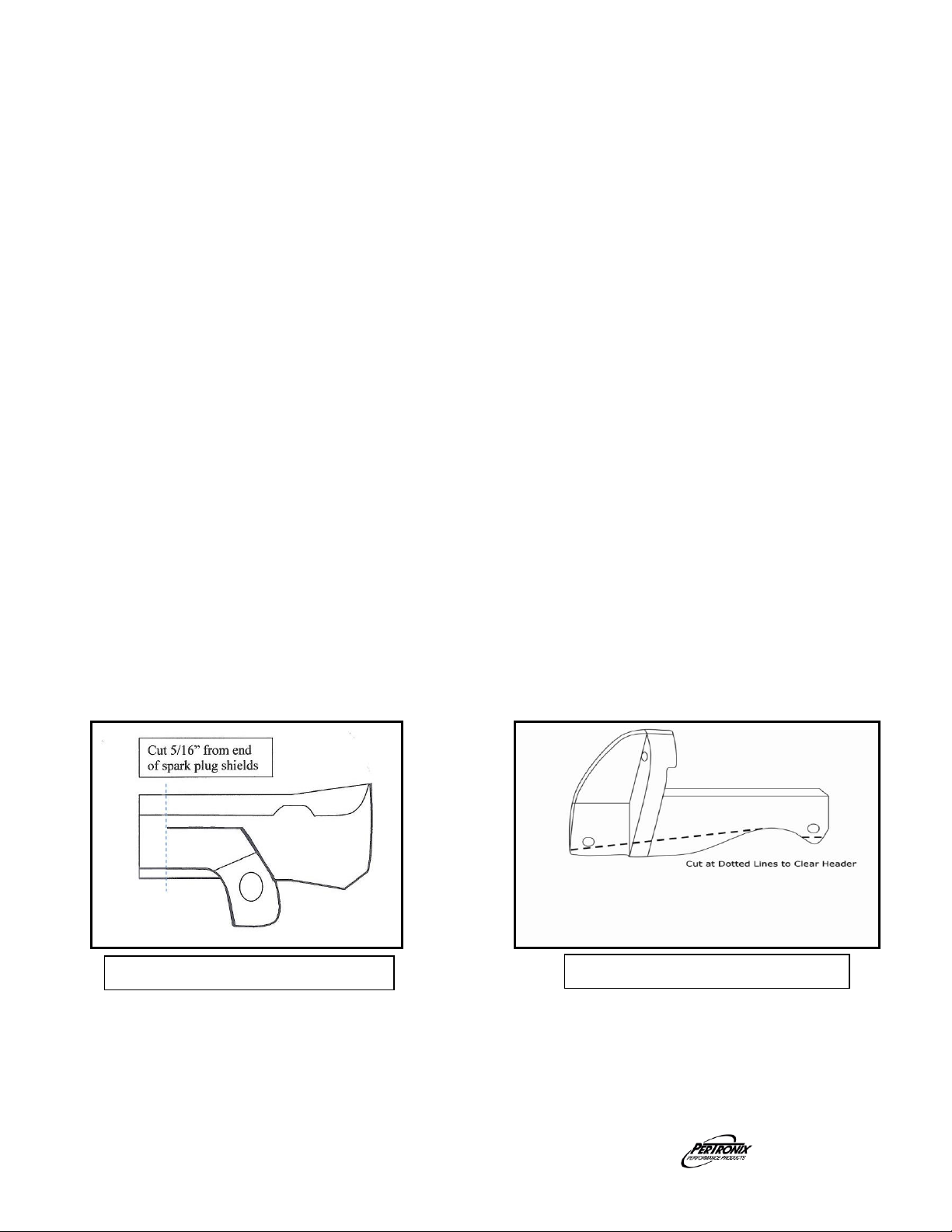
Illustration ‘B’ 73-74 A/C bracket
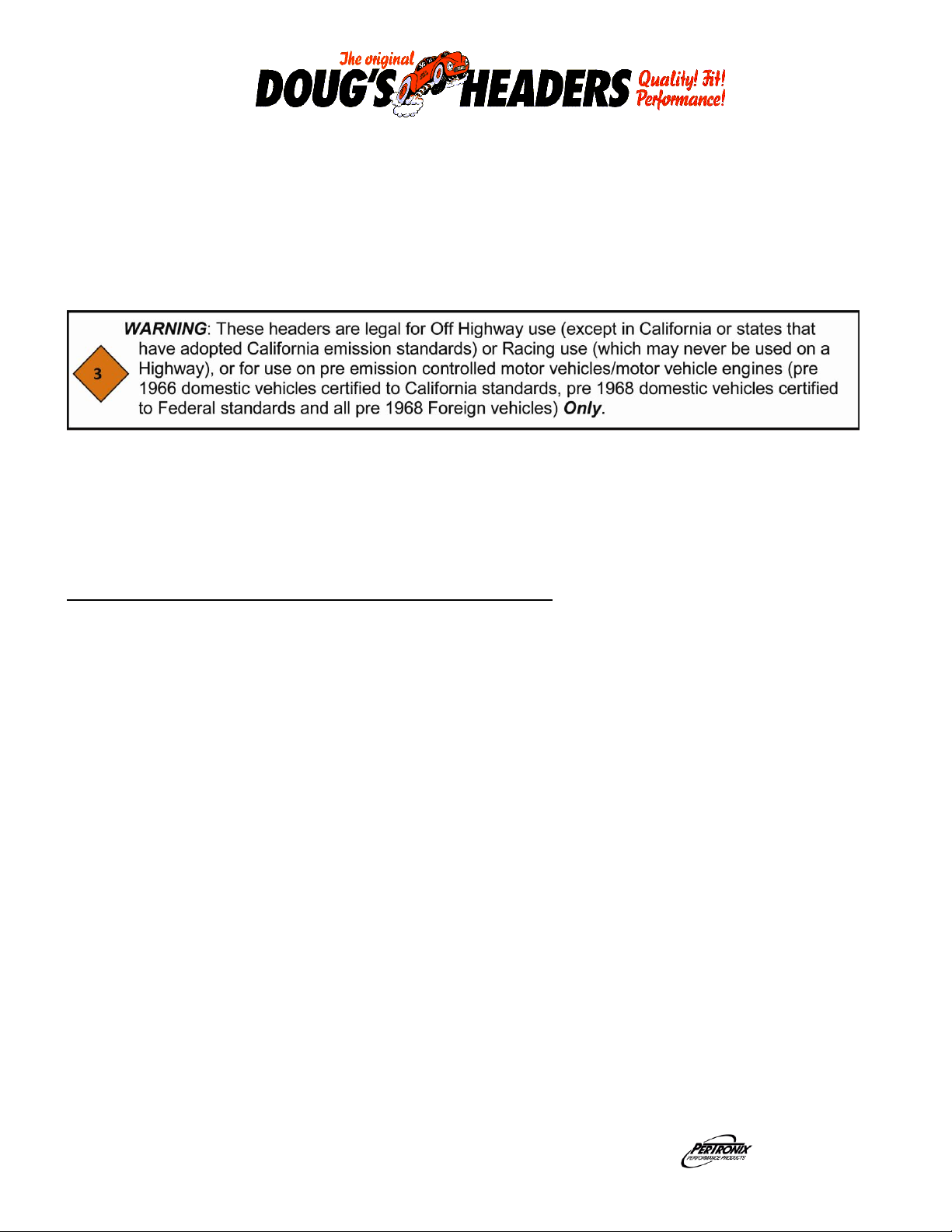
Illustration ‘A’ Spark Plug Shields
ASSEMBLY
1. Install the headers from the bottom of the vehicle. Slide the headers and gaskets into place
and install a bolt at either end of the header to hold them in place and check for proper fit.
2. Check the passenger side header for clearance between the header primary tubes and the
frame/engine perch. A minimum of ¼” is recommended. It may be necessary to remove a
small amount of metal from the frame/engine perch for proper clearance.
3. Tighten the header bolts evenly to a torque of approximately 35 Foot Pounds.
4. Install the spark plugs and connect the wires to the proper plug.
5. If you reuse the spark plug heat shields, you will need to trim 5/16” per Illustration ‘A’
6. Install any accessories that were removed during the header installation.
7. NOTE: 73-75 models with left side A/C will need to modify the bracket per Illustration ‘B’
1968 models with power steering will need to fabricate & install a spacer per Illustration ‘C’
1969-72 models with right side A/C will need to modify the bracket per Illustration ‘D’
1968-72 Models with A/C will need to fabricate and install a spacer under the A/C support
bracket per Illustration ‘E’
8. Install the reducers and determine the connection to the exhaust system.
9. Weld the reducers to the exhaust system and install them onto the headers utilizing the
gaskets and bolts supplied.
10. Check to make sure that all the wiring, brake lines, hoses, etc. are clear of the headers or
any exhaust component.
11. Connect the negative battery cable.
Part No. 0110-003115 Page 2 8-29-2011 DSL
Page 3

Illustration ‘C’ 1968 Power Steering
Illustration ‘D’ 1968-72 A/C Bracket
Illustration ‘E’ 1968-72 A/C Spacers
Part No. 0110-003115 Page 3 8-29-2011 DSL
Page 4

Start the engine and allow it to warm up to operating temperature. Check for any unusual
noises or exhaust leaks. If every thing is OK, stop the engine and tighten all bolts while the
engine is still warm.
NOTE: Check the bolts periodically to make sure they have not loosened. Re-tighten after the
first 500 miles and then again at 1000 miles.
IMPORTANT CHECK LIST
START THE ENGINE
Be sure that all brake lines and fuel lines are clear of headers and/or connector pipes.
All spark plug wires, battery cables, or other electrical components should be clear of
headers and/or connector pipes.
If dipstick tube was removed, make sure it is installed properly and that the dipstick
has been replaced.
Double-check the tightness of all bolts including brackets and accessories.
PARTS LIST
Qty Description
1 Left side header
1 Right side header
2 Header gaskets
2 2 ½” reducers
2 2 ½”, 3 bolt collector gaskets
16 3/8”-16 x 1” header bolts
6 3/8”-16 x 1 1/4” hex head cap screws
6 3/8”-16 hex nut
22 3/8” lock-washers
2 Doug’s Stickers
Part No. 0110-003115 Page 4 8-29-2011 DSL
 Loading...