

Page 1
Corporate Office: PerTronix Inc. 440 E. Arrow Highway, San Dimas, California 91773 * Phone 909.599.5955 * FAX 909.599.6424 * www.dougsheaders.com
HEADER INSTALLATION INSTRUCTIONS
Part # D319
APPLICATION:
1967-1969 CHEVY Camaro / 68-72 Nova/Chevy II
396-502 Big Block (Std. Deck Height Only)
NOTE: These are a large 2 1/8” header primarily designed for racing and as such are not
recommended for cars with comfort options. They are a tight fit and tougher to install then
smaller tube versions available from Doug’s.
NOTE: Vehicles MUST have Original Style Big Block motor stands and motor mounts for
Headers to fit properly. They are no longer available from G.M., but reproductions are
available from most of the Camaro & Nova specialty suppliers. If the motor is mounted on
Small Block frame mounts, you will notice possible Steering Box, Frame, and Idler Arm fit
problems.
NOTE: Will not fit with Power Steering, Column Mounted Stick Shift and not recommended
with air conditioning
PerTronix©
the market. In order to realize the full potential of our good fit, please read and understand these
instructions completely prior to starting work.
Check to make sure you received the proper parts for your application. The header number will be
stamped on the engine flange. If you are unsure you have received the proper parts call before you start.
Be sure to work safe! Whenever you work under the vehicle be sure that it is located on level, solid
ground and is supported by adequate safety stands! Remember: Hot asphalt will not support most
jack stands!
Many factors affect the installation of headers, some of which are broken or aftermarket motor mounts,
accidents that impact the configuration of the frame, and/or the installation of different engines or
aftermarket cylinder heads. Most installations require some welding. If you are uncomfortable with
welding operations, we recommend that you contact a professional exhaust system specialist to install
your new headers.
Attention Customers breaking in new engines: Due to the extreme heat generated during the break-in
process, the appearance of the ceramic coating may be altered in certain areas. The protection
characteristics and thermal barrier properties of the coating is never compromised. It is recommended
that a cast iron manifold or old set of headers be used for this process.
Notice: The coating of these headers can be marred or scratched during installation. If the header needs
to be returned and is damaged, you will be charged for recoat.
thanks you for choosing
DOUG’S HEADERS
, the best fitting, highest quality header on
DISASSEMBLY
1. Disconnect the negative battery cable from the battery.
2. If a car lift is not available, raise the vehicle 3 feet or higher and support it with
adequate safety stands. Make sure the vehicle is on a flat solid surface and is
stable.
0110-003105 Page 1 of 3 8-15-2011 DSL
Page 2

3. Apply penetrating oil to all nuts and bolts to be removed.
4. Remove and mark all spark plug wires and then remove all spark plugs.
5. Remove the Oil filter, Clutch Linkage, Column shift auto trans linkage, Oil dipstick
Tube, Starter, and Air Conditioning Compressor. 1969 Cars with shifter/key
interlock system will have to be removed and disabled.
6. Disconnect the head pipes from the exhaust manifolds and remove the manifolds
7. Remove the gaskets and any gasket material or any carbon deposits that remain
on the head surface. The use of a gasket removal agent will ease the removal of
any gasket material. Use care not to get debris into ports or spark plug holes.
8. At this point it may be necessary to cut the head pipes to allow room to install the
headers. If you are installing a new exhaust system you may cut the head pipes
any where you choose, but if you are using the existing exhaust you need to cut
the head pipes in the proper location so that they will be able to be welded to the
reducers supplied with your headers.
INSTALLATION
1. Place a jack under the oil pan, with a block of wood to prevent damage to the
pan. Loosen the rear transmission mount bolts. Remove the Driver’s side motor
mount bolt and nut.
2. Raise the left side of the engine approximately 1” to 1 1/2”.
3. Starting from below, work the Driver’s side header up into position. Start a bolt
on each end of the header to hold in place. Do not fully tighten at this time.
4. Lower the engine back into position and replace the mount bolt and nut and fully
tighten them. Retighten the transmission bolts.
5. With the header still loose, work the clutch or automatic shifter cross shaft
between the L3 and L4 tubes and into position.
6. Reinstall and fully tighten all linkages and the oil filter.
7. Slip the exhaust gasket in to place and start all the header bolts by hand.
8. Tighten all the bolts evenly starting in the center and working your way out to a
torque of approximately 35 Foot Pounds on iron heads.
9. From below, work the Passenger side header into position. Start a bolt on each
end of the header to hold in place. Do not fully tighten at this time.
10. Re install the starter motor.
11. Slip the exhaust gasket in to place and start all the header bolts by hand.
12. Tighten all the bolts evenly to a torque of approximately 35 Foot Pounds.
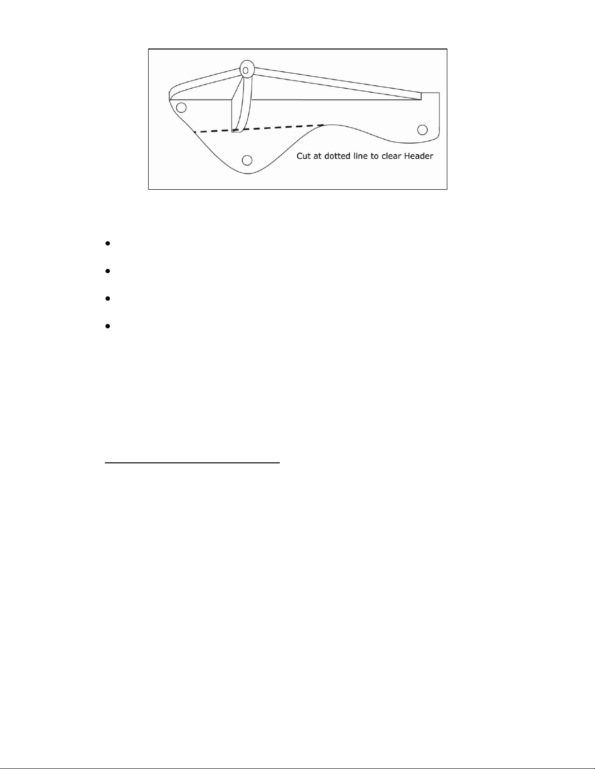
13. Doug’s does not recommend A/C with this header, but Air Conditioned cars will
require the modification to the bracket as shown in Illustration A.
14. Install the oil dipstick tube.
15. Install the reducers using the supplied bolts, washers, nuts and gaskets.
16. Weld the exhaust system to the reducers.
17. Install the spark plugs and connect the wires to the proper plug.
18. Check to make sure that all the wiring, fuel lines, transmission cooler lines, brake
lines, hoses, etc. are clear of the headers or any exhaust components and
reroute or relocate those components as necessary.
19. Check the oil level.
20. Connect the battery cable.
0110-003105 Page 2 of 3 8-15-2011 DSL
Page 3
Be sure that all brake lines and fuel lines are clear of headers and/or
connector pipes.
All spark plug wires, battery cables, or other electrical components should be
clear of headers and/or connector pipes.
If dipstick tube was removed, make sure it is installed properly and that the
dipstick has been replaced.
Double-check the tightness of all bolts including brackets and accessories.
Start the engine and allow it to warm up to operating temperature. Check for any
unusual noises or exhaust leaks. If every thing is OK, stop the engine and tighten all
bolts while the engine is still warm. NOTE: Check the bolts periodically to make
sure they have not loosened. Re-tighten after the first 500 miles and then again at
1000 miles
Illustration A; Air conditioning Bracket.
IMPORTANT CHECK LIST
START THE ENGINE
PARTS LIST
Qty Description
1 Left Side Header
1 Right Side Header
2 Header Gaskets
2 3 ½” Reducers
2 3 ½”, 3 Bolt Collector Gaskets
16 3/8”-16 X 1” Header Bolts
6 3/8”-16 X 1 ¼” Hex Head Cap Screws
6 3/8”-16 Hex Nuts
22 3/8” Lock-Washers
2 Doug’s Stickers
0110-003105 Page 3 of 3 8-15-2011 DSL
 Loading...