

Page 1
For Part Numbers:
D190500 D190509 D190600 D190609
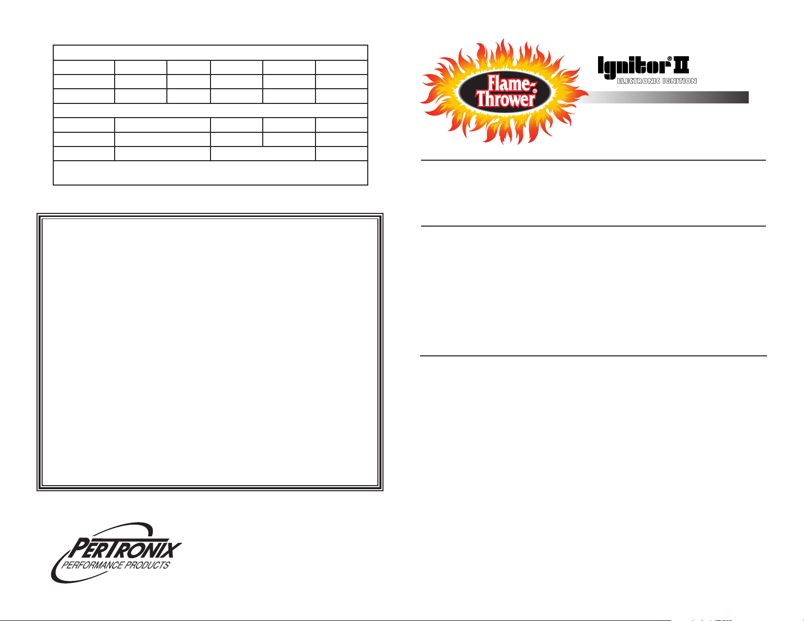
Recommended Flame-Thrower II & HV Coils
Application Primary resistance Chrome Black Epoxy
Ignitor II Only 0.6 ohm 45001 45011 45111
Ignitor II Only 0.45 ohm E-Core HV Coil 60104
NOTE: REMOVE OR BYPASS EXTERNAL BALLAST RESISTOR OR RESISTANCE WIRE WHEN
INSTALLING THE RECOMMENDED FLAME-THROWER II OR HV E-CORE COIL.
LIMITED WARRANTY
PerTronix, Inc. warrants to the original Purchaser of its Flame-Thrower billet distributor that the product shall be free from defects in material and workmanship (normal wear and tear excluded) for a period of 12 months from the date of
purchase.
If within the period of the foregoing warranty PerTronix finds, after inspection, that
the product or any component thereof is defective, PerTronix will, at its option, repair
such products or component or replace them with identical or similar parts PROVIDED
that within such period Purchaser:
1. Promptly notifies PerTronix, in writing, of such defects.
2. Delivers the defective product or component to
PerTronix (Attn: Warranty) with proof of purchase date; and
3. Has installed and used the product in a normal and proper
manner, consistent with PerTronix printed instructions
THE FOREGOING LIMITED WARRANTY IS EXCLUSIVE AND IN LIEU OF
ALL OTHER WARRANTIES, WHETHER EXPRESS OR IMPLIED, INCLUDING ANY
IMPLIED WARRANTY OF MERCHANTABILITY OR FITNESS FOR A
PARTICULAR PURPOSE.
THE FURNISHING OF A REPAIR OR REPLACEMENT COMPONENT
OR COMPONENTS SHALL CONSTITUTE THE SOLE REMEDY OF PURCHASER
AND THE SOLE LIABILITY OF PerTronix WHETHER ON WARRANTY, CONTRACT
OR FOR NEGLIGENCE, AND IN NO EVENT WILL PerTronix BE LIABLE FOR
MONEY DAMAGES WHETHER DIRECT OR CONSEQUENTIAL.
440 East Arrow Highway
San Dimas, CA 91773
909-599-5955
www.pertronix.com
DISTRIBUTOR INSTALLATION
INSTRUCTIONS FOR:
FORD-OHC, X-FLOW, TWIN CAM
GENERAL INFORMATION
1. IMPORTANT: Read all instructions before starting installation.
2. For 12-volt negative ground systems only.
3. New spark plug wires may be required.
4. Solid core spark plug wires MUST NOT be used.
DISTRIBUTOR REMOVAL
1. Crank the engine until the first cylinder in the firing order is at TDC "Top Dead
Center" on its compression stroke. The timing indicator should point to TDC or 0.
2. Remove the distributor cap, and make sure that the rotor is pointing towards the
contact on the distributor cap for the first cylinder in the firing order.
3. Disconnect the battery negative (-) cable.
4. Disconnect all wires and hoses attached to the distributor.
5. Remove the distributor hold down bolt.
6. Remove the distributor by lifting up on the distributor housing while slightly
turning the rotor.
7. Check the distributor gear for signs of excess wear, or potential problems.
DISTRIBUTOR INSTALLATION
Note: Original hold down clamp must be used with new Flame-Thrower
distributor. Hold down bracket must be free of paint and corrosion, this will insure
that a proper ground is made to the engine block.
1. Remove the Flame-Thrower distributor cap.
2. Lubricate the distributor gear and distributor shaft with clean engine oil.
3. Turn the shaft so that when the distributor is placed into the engine, the rotor
position matches that of the original distributor. As the distributor drops down,
the rotor will turn slightly as it engages with the camshaft gear. Adjust for this
rotation by turning the rotor a few degrees prior to the gear engagement. Several
attempts may be necessary to achieve the proper rotor position. Note: The
distributor flange will be flush with the engine block if the installation is done
properly.
4. Place the distributor cap onto the housing.
5. Turn the housing so that the terminal, that represents the first cylinder in the
firing order, lines up with the rotor.
6. Install the distributor hold down bolt and tighten completely. Once the ignition
timing is adjusted the hold down clamp should be tightened completely.
7. Tighten the cap into place and install the spark plug wires in the proper firing
order.
10-13
0017-004425
Page 2
8. For Vacuum advance distributors:
Locate the vacuum hose that was previously attached to the vacuum advance
canister. This hose should originate at a ported vacuum source. Some applications have vacuum advance hoses attached to a manifold vacuum source, due
to the performance advance curve, we recommend that you relocate this hose
to a ported vacuum source. After setting initial timing the hose will be unplugged
and attached to the vacuum advance on the distributor.
For Non-vacuum advance distributors:
Locate the vacuum hose that was previously attached to the vacuum advance
canister. Remove the vacuum hose and plug the vacuum port.
WIRING
The Flame-Thrower distributor can be used in conjunction with most
Ignition coils rated at 0.45 ohms or greater. For optimum performance purchase
and install a 0.6 ohm Flame-Thrower II or 0.45 ohm HV high performance coil.
1. Many vehicles came equipped with ballast resistors or resistance wires. To
achieve optimum performance we recommended removal of these
components.
2. Determine the proper wire length, and attach the provided terminals. (Use a
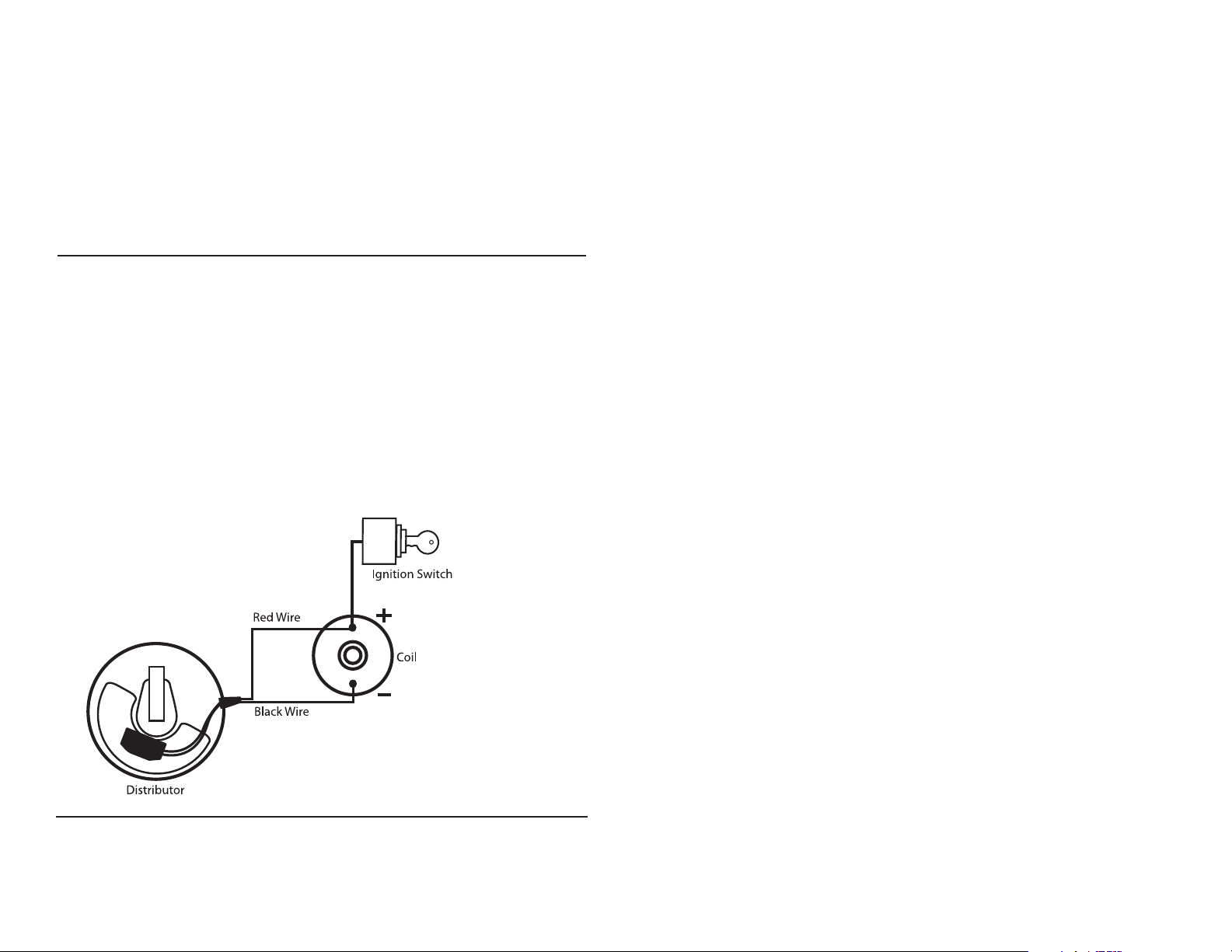
designated wire crimping tool to achieve an adequate connection)
3. Attach the Red wire to the coil positive terminal or a 12-volt ignition source.
Note: Original ignition wire must be connected to the (+) positive side of the
Ignition coil.
4. Attach the Black wire to the coil negative terminal.
5. Check to insure correct polarity and that all connections are tight.
6. Reconnect the battery negative cable.
COMMON QUESTIONS AND ANSWERS
Q. The engine will not start or runs rough. What is the problem?
A. Check all connections to insure that they are tight, and in the proper location.
Make sure that the red wire from the Flamethrower distributor is supplied with a
full 12 volts. The Flame-Thrower distributor uses Ignitor II technology and is designed
to sense high current levels, and shut off before damage occurs. Check all wires
for shorts, correct polarity and that the ignition coil’s primary resistance level is
acceptable.
Q. The vehicle will start, but then die. After waiting it will start again. What is wrong?
A. Check for a “Low Voltage Problem.” If the voltage supplied to the Flame-Thrower
distributor red wire is insufficient, the system may run for a period of time, and
then shut down as the voltage drops due to engine heat. The period may vary
from minutes to hours depending on available voltage and wiring condition.
Q. How do I check for a “Low Voltage Problem” or determine if I am getting ade-
quate voltage?
A. To quickly test for a “Low Voltage Problem” or for adequate voltage, remove the
Flame-Thrower distributor red wire from the coil positive terminal. Attach a jumper
wire from the battery positive terminal to the distributor red wire. Try to start the
vehicle. If the vehicle starts, low voltage is the problem.
Q. How do I check my coil for primary resistance?
A. Remove all wires from the coil. Set the ohmmeter to the lowest scale. Attach one
lead of the meter to the positive coil terminal. Attach the other lead to the negative
coil terminal. The Flame-Thrower distributor is compatible with coils having a resis-
tance of 0.45 ohms or greater. See chart for compatible Flame-Thrower coils.
FINAL ADJUSTMENTS
1. Start the engine and set the initial timing.
2. Tighten the distributor hold down clamp.
3. For vacuum advance distributors, connect the vacuum hose to the vacuum
advance canister.
Q. May I modify the length of the wires?
A. Yes, you may cut the wires to any length your application requires. You may also
add lengths of wire if needed (20-gauge). Make sure that all wire splices are clean
and the connections are tight.
Q. Will the Flame-Thrower distributor work with aftermarket capacitive discharge boxes?
A. Yes, the Flame-Thrower distributor is compatible with most CD boxes in the same
respect as points. Use the CD box wiring instructions for point systems and treat
the Ignitor II black wire as a point wire. The Flame-Thrower red wire should be
attached to the 12-volt power source.
Q. How can I receive additional help?
A. Check our web site for current trouble shooting tips and up to date technical
information. Log on to www.pertronix.com. You may also contact our tech line at
(909-547-9058)
 Loading...