

Page 1

CAST DiSTribuTor
inSTAllATion inSTruCTionS
0017-00447608-11
LIMITED WARRANTY
PerTronix, Inc. warrants to the original Purchaser of its Flame-Thrower Cast
distributor that the product shall be free from defects in material and workmanship
(normal wear and tear excluded) for a period of 12 months from the date of
purchase.
If within the period of the foregoing warranty PerTronix finds, after inspection,
that the product or any component thereof is defective, PerTronix will, at its option,
repair such products or component or replace them with identical or similar parts
PROVIDED that within such period Purchaser:
1. Promptly notifies PerTronix, in writing, of such defects.
2. Delivers the defective product or component to
PerTronix (Attn: Warranty) with proof of purchase date; and
3. Has installed and used the product in a normal and proper
manner, consistent with PerTronix printed instructions
THE FOREGOING LIMITED WARRANTY IS EXCLUSIVE AND IN LIEU OF
ALL OTHER WARRANTIES, WHETHER EXPRESS OR IMPLIED, INCLUDING
ANY IMPLIED WARRANTY OF MERCHANTABILITY OR FITNESS FOR A
PARTICULAR PURPOSE.
THE FURNISHING OF A REPAIR OR REPLACEMENT COMPONENT
OR COMPONENTS SHALL CONSTITUTE THE SOLE REMEDY OF
PURCHASER AND THE SOLE LIABILITY OF PerTronix WHETHER ON
WARRANTY, CONTRACT OR FOR NEGLIGENCE, AND IN NO EVENT WILL
PerTronix BE LIABLE FOR MONEY DAMAGES WHETHER DIRECT OR
CONSEQUENTIAL.
440 East Arrow Highway
San Dimas, CA 91773
909-599-5955
www.pertronix.com
GENERAL INFORMATION
IMPORTANT: Read all instructions before starting installation.1.
For 12-volt negative ground systems only.2.
Flame-Thrower Cast distributors come with hardened steel distributor gears which 3.
should not be used in applications with a billet camshaft. Consult camshaft manufacturer
for distributor gear compatibility.
Engines that have been decked, had significant cylinder head milling or oil pump modi-4.
fication should be checked for oil pump bind and proper cam gear engagement prior to
installation.
The Ignitor is compatible only with a “resisted style” coil. Eight cylinder engines require a 5.
minimum of 1.5 ohms of resistance.
If your Ignition coil has the proper primary resistance, remove or bypass all external 6.
resistors. Do not remove resistors if the coil primary resistance is lower than specified.
DISTRIBUTOR REMOVAL
Crank the engine until it is positioned at top dead center on a compression 1.
stroke. The timing indicator should point to 0.
Remove the distributor cap, and make sure that the rotor is pointing towards the 2.
first cylinder in the firing order.
Disconnect the battery negative (-) cable.3.
Disconnect all wires and hoses attached to the distributor. 4.
Remove the distributor hold down.5.
Remove the distributor by lifting up on the distributor housing while slightly turn-6.
ing the rotor.
Check the distributor gear for signs of excess wear, or potential problems.7.
DISTRIBUTOR INSTALLATION
1. Remove the Flame-Thrower Cast distributor cap.
2. Install the distributor gasket over the gear, and up to the distributor collar.
Use a small amount of gasket adhesive to help hold the gasket in place.
3. Lubricate the distributor gear and distributor shaft with clean engine oil.
4. Turn the shaft so that when the distributor is placed into the engine, the
rotor position matches that of the original distributor. As the distributor drops
down, the rotor will turn slightly as it engages with the camshaft gear.
Adjust for this rotation by turning the rotor a few degrees prior to the gear
engagement. Several attempts may be necessary to achieve the proper
rotor position. The distributor collar should sit completely flat on the intake
manifold or block.
Page 2
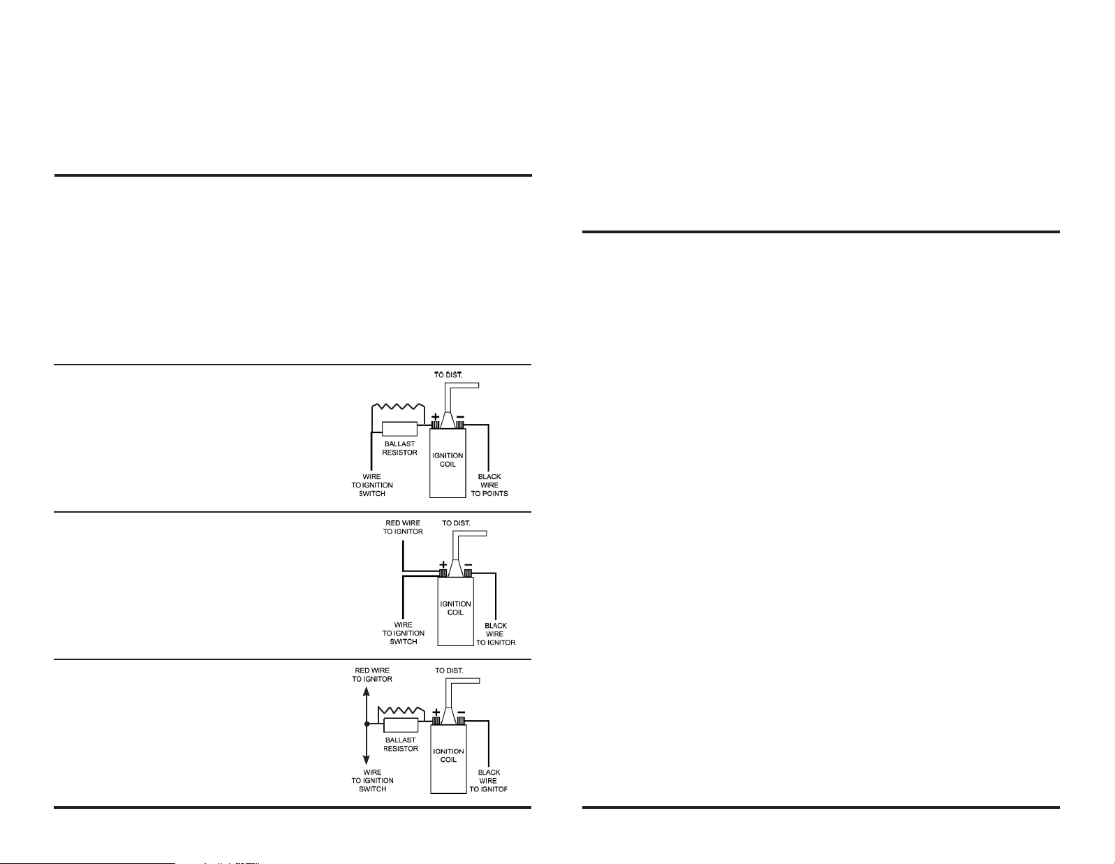
FIGURE 1
(CONVENTIONAL POINT SYSTEM)
WIRING DIAGRAM
WITH RESISTOR WIRE OR
BALLAST RESISTOR
FIGURE 2
(IGNITOR SYSTEM - WITHOUT BALLAST
RESISTOR)
THE BLACK WIRE MUST BE CONNECTED •
TO THE NEGATIVE (-) SIDE OF THE COIL.
THE RED WIRE MUST BE CONNECTED •
TO THE POSITIVE SIDE OF THE COIL.
FIGURE 3
(IGNITOR SYSTEM - WITH BALLAST
RESISTOR)
THE BLACK WIRE MUST BE CONNECTED •
TO THE NEGATIVE (-) SIDE OF THE COIL.
THE RED WIRE MUST BE CONNECTED •
TO THE 12-VOLT SIDE OF THE BALLAST
RESISTOR OR RESISTANCE WIRE.
RESISTOR
WIRE
RESISTOR
WIRE
WIRING INSTRUCTIONS
NOTE: A BALLAST RESISTOR OR RESISTOR WIRE MAY OR MAY NOT BE INCLUDED IN THE ORIGINAL 1.
EQUIPMENT.
Connect the Ignitor black wire to the negative (-) side of the ignition coil.2.
For installations that do not use a primary ballast resistor, connect the Ignitor red wire to the posi-3.
tive (+) side of the ignition coil. (See Figure 2)
For installations that use a primary ballast resistor, connect the Ignitor red wire to the ignition 4.
switch side of the resistor. (See Figure 3).
Reconnect battery and make sure all wires are connected.5.
The engine can now be started. Let the engine run for a few minutes and then set the timing in the 6.
conventional manner.
5. Place the distributor cap onto the housing.
6. Turn the housing so that the terminal, that represents the first cylinder in
the firing order, lines up with the rotor.
7. Install the distributor hold down and tighten the hold down bolt slightly.
insure that the distributor is grounded properly thru the hold down bracket.
Once the ignition timing is adjusted the hold down bolt should be tightened
completely.
8. Tighten the cap into place and install the spark plug wires in the proper
firing order.
9. Locate the vacuum hose that was previously attached to the vacuum
advance canister. This hose should originate at a ported vacuum source.
For Vacuum advance distributors:
Temporarily plug the end of this hose to allow proper timing. After setting
initial timing the hose will be unplugged and attached to the vacuum
advance on the distributor.
Ignitor COMMON QUESTIONS AND ANSWERS
Q. What is the first thing I should check if the engine would not start?
A. Make certain all wires are connected securely to the proper terminals.
Q. The engine will not start or runs rough. Are there any tests I can do?
A. Yes, remove the red ignitor wire from the coil. Connect jumper wire from the positive side of the battery to the red
ignitor wire just removed from the coil. If the engine starts, then you have a low voltage problem . Remember this is
just a test. Not intended for permanent installation.
Q. How can I fix a low voltage problem?
A. First, if you have an external ballast resistor or resistance wire, connect the red ignitor wire to the ignition wire prior
to the ballast resistor or resistance wire. Second, if you do not have a an external resistor you must connect the ignitor
red wire to a 12-volt source that is controlled by the ignition switch.
Q. Should I remove the starter bypass wire?
A. No, the starter bypass wire is needed to provide voltage while star ting (cranking).
Q. What type of coil do I need?
A. The ignitor is compatible only with a “points type” coil. Eight cylinder engines require a minimum of 1.5 Ohms of
resistance in the primar y circuit.
Q. How do I check my coil for resistance?
A. First you need an ohmmeter. Remove all the wires from the coil. Attach the ohmmeter to both the positive and nega-
tive terminals. The reading should be 1.5 Ohms or greater for eight cylinder engines and 3.0 Ohms or greater for six
cylinder engines. (Your local auto parts store can do this for you if you don’t have an ohmmeter)
Q. What do I do if my coil does not have enough resistance?
A. You may purchase and install a ballast resistor from your local auto parts store. You may also choose to purchase a
Flamethrower 40,000-volt coil, which provides resistance internally. Note: Many vehicles come with ballast resistor or
resistance wire. These applications do not need an additional resistor.
Q. What happens if you leave the ignition switch on when the engine is not running?
A. This can cause your coil to overheat, which may cause permanent damage to the coil and the ignitor.
Q. May I modify the length of the wires?
A. Yes, you can cut the wires to any length your application may require. You may also add length of wire if needed
(20-gauge wire). Please make sure all wire splice are clean and connections are secure.
Q. How can I get additional help?
A. Call our tech line (909-599-5955) for any fur ther instructions or questions.
 Loading...