

Page 1
Corporate Office: PerTronix Inc. 440 E. Arrow Highway, San Dimas, California 91773 * Phone 909.599.5955 * FAX 909.599.6424 * www.dougsheaders.com
HEADER INSTALLATION INSTRUCTIONS
Part # D104
Application: AMC
68-74 Javelin/AMX, 71-74 Matador
PerTronix©
order to realize the full potential of our good fit, please read and understand these instructions completely prior to starting
work.
Check to make sure you received the proper parts for your application. The header number will be stamped on the
engine flange. If you are unsure you have received the proper parts call before you start work.
Be sure to work safe! Whenever you work under the vehicle be sure that it is located on level, solid ground and is
supported by adequate safety stands! Remember: Hot asphalt will not support most jack stands!
Many factors affect the installation of headers, some of which are broken or aftermarket motor mounts, accidents that
impact the configuration of the frame, and/or the installation of different engines or aftermarket cylinder heads. Most
installations require some welding. If you are uncomfortable with welding operations, we recommend that you contact a
professional exhaust system specialist to install your new headers.
Attention Customers breaking in new engines: Due to the extreme heat generated during the break-in process, the
appearance of the ceramic coating may be altered in certain areas. The protection characteristics and thermal barrier
properties of the coating is never compromised. It is recommended that a cast iron manifold or old set of headers be used
for this process.
Notice: The coating of these headers can be marred or scratched during installation. If the header needs to be returned
and is damaged, you will be charged for recoat.
1. Disconnect the negative battery cable from the battery.
2. If a car lift is not available, raise the vehicle 3 feet or higher and support it with adequate safety
stands. Make sure the vehicle is on a flat solid surface and is stable.
3. Apply penetrating oil to all nuts and bolts to be removed.
4. Remove and mark all spark plug wires and then remove all spark plugs and the starter motor.
5. Remove the Oil Dipstick Tube and remove the Clutch Linkage on stick shift cars or the
Transmission filler tube from the back of the head if Automatic.
6. Disconnect the head pipes from the exhaust manifolds and remove the stock exhaust manifolds.
7. If the car has an Air Injection pump this will have to be removed as these headers will not work
with it.
8. Remove the gaskets and any gasket material or any carbon deposits that remain on the head
surface. The use of a gasket removal agent or scraper will ease the removal of any gasket
material. Use care not to get debris into ports or spark plug holes.
thanks you for choosing
DOUG’S HEADERS
DISASSEMBLY
, the best fitting, highest quality header on the market. In
Part No. 0110-003103 Page 1 of 3 8-15-11 DSL
Page 2

9. At this point it may be necessary to cut the head pipes to allow room to install the headers. If you
are installing a new exhaust system you may cut the head pipes any where you choose, but if you
are using the existing exhaust you need to cut the head pipes in the proper location so that they
will be able to be welded to the reducers supplied with your headers.
INSTALLATION
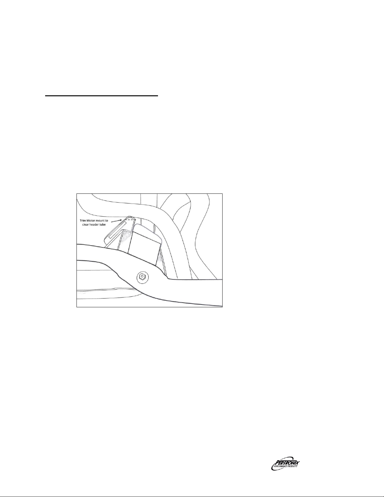
1. 73-74 Javelins and 74-75 Matadors will require modification of the driver’s side motor mount. The
front upper corner will need to be cut. See Photo A.
2. Starting with the driver’s side, work the header up into position from below.
3. Slip the gasket into position and start all the supplied header bolts and lock washers.
4. Tighten all the bolts in an even pattern working form the center outwards to a final torque of 35 ft
lbs.
5. Place a floor jack under the oil pan with a flat board for support. Loosen the transmission mount
bolts.
6. Remove the passenger’s side motor mount bolt and raise the motor approx 1”.
7. From below, work the passenger’s side header up into position and loosely install front bolt only.
8. Lower the motor back into position. Reinstall the motor mount bolt and tighten the transmission
mount.
9. With the header still loose, re install the starter motor.
10. Slip the gasket into position and start all the supplied header bolts and lock washers.
11. Tighten the header bolts evenly starting from the center to a final torque of 35 ft lbs.
14. Reinstall Oil Dipstick tube, and Clutch Linkage or Transmission fill tube, it might be necessary to
fabricate and extension for the filler tube bracket to fit around the headers.
15. Bolt the supplied reducers to the headers using the supplied gaskets, bolts, nuts, and washers. If
reusing the stock exhaust, cut the headpipes so that they meet the reducers and weld in place.
16. Install the spark plugs and connect the wires to the proper plug.
17. Connect the battery cables.
IMPORTANT CHECK LIST
Be sure that all brake lines, transmission lines, and fuel lines are clear of headers and/or
connector pipes.
All spark plug wires, battery cables, or other electrical components should be clear of
headers and/or connector pipes.
If dipstick tube was removed, make sure it is installed properly and that the dipstick has
been replaced.
Double-check the tightness of all bolts including brackets and accessories.
START THE ENGINE
Start the engine and allow it to warm up to operating temperature. Check for any unusual noises
or exhaust leaks. If everything is OK, stop the engine and tighten all bolts while the engine is still
warm. NOTE: Check the bolts periodically to make sure they have not loosened. Re-tighten after
the first 500 miles and then again at 1000 miles
Part No. 0110-003103 Page 2 of 3 8-15-11 DSL
Page 3
PARTS LIST
Qty Description
1 Left Side Header
1 Right Side Header
2 Header Gaskets
2 3 1/2” Reducers
2 3 1/2” Collector Gaskets
12 3/8”-16 X 1” Header Bolts
6 3/8”-16 X 1 ¼” Hex Head Cap Screws
6 3/8”-16 Hex Nuts
18 3/8” Lock-Washers
2 Doug’s Stickers
Photo A: Motor Mount Modification
Part No. 0110-003103 Page 3 of 3 8-15-11 DSL
 Loading...