

Page 1
LIMITED WARRANTY
Pertronix, Inc. Warrants to the original Purchaser of its solid-state ignition system
(product) that the Ignitor, magnet assembly and wiring (components) shall be free from defects
in material and workmanship for a period of (30) months from the date of purchase.
If within the period of the foregoing warranty Pertronix finds, after inspection, that
the product or any component thereof is defective, Pertronix will, at its option, repair such
products or component or replace them with identical or similar parts PROVIDED that within
such period Purchaser:
1. Promptly Notifies PerTronix, in writing, of such defects.
2. Delivers the defective products product or component to Pertronix (ATTN: Warranty)
with proof of purchase date; and
3. Has installed and used the product in a normal and Proper manner, consistent with
Pertronix printed instructions.
THE FORGOING LIMITED WARRANTY IS EXCLUSIVE AND IN LIEU OF ALL
OTHER WARRANTIES, WHETHER EXPRESSED OR IMPLIED, INCLUDING AND IMPLIED
WARRANTY OR MERCHANTABILITY OR FITNESS FOR A PURPOSE.
THE FURNISHING OF A REPAIR OR REPLACEMENT COMPONENTS SHALL CONSTITUTE
THE SOLE REMEDY OF PURCHASER AND THE SOLE LIABILITY OF PerTronix WHETHER
ON WARRANTY, CONTRACT
BE LIABLE FOR MONEY DAMAGES WHETHER DIRECT OR CONSEQUENTIAL.
OR FOR NEGLIGENCE, AND IN NO EVENT WILL PerTronix
440 E. Arrow Highway, San Dimas, CA. 91773
909-599-5955 www.pertronix.com
12-VOLT NEGATIVE GROUND INSTRUCTIONS
FOR PART NUMBERS: 9MR-162
GENERAL INFORMATION
1. IMPORTANT: Read all instructions before star ting installation.
2. DO NOT USE WITH SOLID CORE SPARK PLUG WIRES.
The Ignitor II ignition can be used in conjunction with most ignition coils rated at
3.
0.45 ohms or greater.
4. All external resistors must be removed to achieve optimum performance from the
Ignitor II ignition system.
5. The Ignitor II is compatible as a trigger for most electronic boxes.
DISASSEMBLY
1. PRIOR TO INSTALLATION TURN IGNITION SWITCH OFF OR
DISCONNECT THE BATTERY
2. Disconnect the point wires from the negative (-) terminal of the Ignition coils.
3. Remove the distributor cap. Do not disconnect spark plug wires. Examine cap for
wear or damage. Replace as needed.
4. Remove the screw that retains the distributor rotor. Note position of the rotor.
The red dot on the rotor and the dot on the distributor shaft should be aligned.
Remove the rotor.
5. Remove the three screws that hold the bearing support to the distributor housing.
Remove the bearing support and bearing.
6. Remove the points, condensers, and the grommets from the distributor. If
present, remove the point lubricating felt and bracket.
7. Remove the snap ring from the top of the point cam.
8. Clean the base of the distributor housing and distributor cam.
IGNITOR INSTALLATION
1. Place the Ignitor II adapter plate into the distributor housing. Align the notches
in the plate with the distributor. Make sure the “A” and “B” stamped into the plate
align with the corresponding marks in the distributor housing and the wire exits.
2. Use the provided screws to tighten the plate in place.
3. Install each module onto the adapter plate studs. Use the provided lock washers
and nuts to tighten the modules in place.
4. Insert wires from each module into the wire exit holes in the distributor housing.
Pull the rubber grommets into place and gently pull the excess wire out of the
distributor. Make sure wires do not interfere with any moving parts.
5. Install magnet sleeve over the distributor shaft, onto point cam. Rotate the sleeve
until a slight locating position is felt before applying pressure. Press down firmly
insuring sleeve is fully seated.
6. Module and magnet sleeve air gap is not adjustable.
Page 2
7. Install snap ring, bearing and bearing support.
8. Install the rotor by aligning the dots on the shaft and rotor.
9. Install the distributor cap. Make sure all spark plug wires are securely attached.
Warning!
DO NOT USE WITH SOLID CORE SPARK PLUG WIRES.
10. See Wiring Instructions.
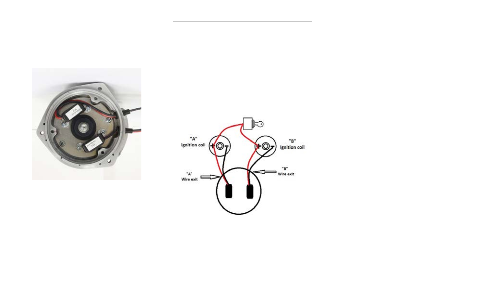
WIRING INSTRUCTIONS
The Ignitor II ignition can be used in conjunction with most ignition coils rated at 0.45
ohms or greater. For optimum performance purchase and install the Flamethrower II
high performance coil.
1. Use the provided ring terminals to attach each of the black Ignitor wires to the
negative (-) terminal of each coil.
2. Attach each of the red Ignitor wires to the positive (+) terminal of each coil.
3. The module wires that exit the distributor at the “A” location should be attached to
the “A” coil and the module that exit the “B” location should be connected to the
“B” coil.
4. Check and insure that the polarity is correct, and that all connections are tight.
5. Reconnect battery and make sure all wires are connected.
6. The engine can now be started. Let the engine run for a few minutes and then set
the Ignition timing in the conventional manner.
COMMON QUESTIONS AND ANSWERS
Q. The engine will not start or runs rough. What is the problem?
A. Perform Power and Ground Checks. Check all connections to insure that they are
tight, and in the proper location. Check all grounds; if a distributor ground wire was
removed make sure that it was reattached properly. Make sure that the red Ignitor II
wire is supplied with a full 12 volts. The Ignitor II is designed to sense high current
levels, and shut off before damage occurs. Check all wires for shorts, correct polarity
and that the ignition coil’s primary resistance level is acceptable.
Q. . The vehicle will start, but then die. After waiting it will start again. What is wrong?
A. Perform Power and Ground Checks. The Ignitor II may have a “Low Voltage Problem.”
If the voltage supplied to the red Ignitor II wire is insufficient, the system may run for a
period of time, and then shut down as the voltage drops due to engine heat. The period
may vary from minutes to hours depending on available voltage and wiring condition. To
remedy this condition refer to steps 2-4 of the wiring instructions.
Q. How do I check for a “Low Voltage Problem” or determine if I am getting adequate
voltage?
A. Perform Power and Ground Checks. Also, to quickly test for a “Low Voltage Problem”
or for adequate voltage, remove the Ignitor II red wire from the coil positive terminal.
Attach a jumper wire from the battery positive terminal to the Ignitor II red wire. Try
to start the vehicle. If the vehicle star ts with this test refer to steps 2-4 of the wiring
instructions for further information.
Q. How do I check my coil for primary resistance?
A. Remove all wires from the coil. Set the ohmmeter to the lowest scale. Attach one
lead of the meter to the positive coil terminal. Attach the other lead to the negative coil
terminal.
Q. May I modify the length of the wires?
A. Yes, you may cut the wires to any length your application requires. You may also add
lengths of wire if needed (20-gauge). Make sure that all wire splices are clean and the
connections are tight.
Q. Will the Ignitor II work with aftermarket capacitive discharge boxes?
A. Yes, the Ignitor II is compatible with most CD boxes in the same respect as points.
Use the CD box wiring instructions for point systems and treat the Ignitor II black wire
as a point wire. The Ignitor II red wire should be attached to the 12-volt power source.
Q. Will the electronic shift assist in an OMC boat work with the Ignitor II?
A. The Ignitor II will work with all OMC stern-drive applications, when our “diode fix” is
used. If you’ve purchased a kit that didn’t include the “diode fix” diagram, call our tech
line.
Q. How can I receive additional help?
A. Check our web site for current trouble shooting tips and up to date technical
information. Log on to www.pertronix.com. You may also contact our tech line at
(909-547-9058)
 Loading...