

Page 1
12-VOLT NEGATIVE GROUND INSTRUCTIONS
PRIOR TO INSTALLATION TURN IGNITION SWITCH OFF OR
DISCONNECT THE BATTERY.
1. Some magnet sleeves have green or blue tape, DO NOT REMOVE IT.
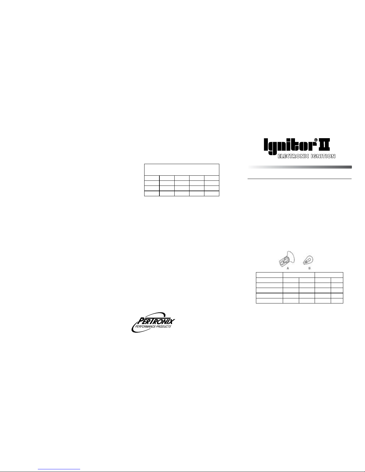
2. 91541, 91542, 91561, and 91562 Ignitor kits only: Two types of rotors
are used in Prestolite distributors. These are shown below. The Ignitor
only works with the type of rotor shown on figure “A”. If the rotor is of
the type shown in figure in figure “B” a new cap and rotor will have to be
purchased.
Ignitor # 91541, 91542 91561, 91562
Cap Rotor Cap Rotor
Prestolite 3-129 4-93 3-127 4-93
Borg Warner C207 D181 C205 D181
Echlin (Napa) AL165 AL150 AL155 AL150
Standard (SMP) AL149 AL168 AL480 AL168
12-VOLT NEGATIVE GROUND INSTRUCTIONS
FOR PART NUMBERS:
91541 91542 91543 91545 91548
91549 91561 91562 91568 91585A
92541 91567A
PRESTOLITE DISTRIBUTORS
3. Remove distributor cap and rotor from distributor. Do not disconnect spark
plug wires from cap. Examine cap and rotor for wear or damage. Replace
as needed.
4. Remove the point wire from the coil negative terminal.
5. Remove the screws retaining the breaker plate and remove the complete
breaker plate assembly from the distributor housing.
GENERAL INFORMATION
1. IMPORTANT: Read all instructions before starting installation.
2. DO NOT USE WITH SOLID CORE SPARK PLUG WIRES.
3.
The Ignitor II ignition can be used in conjunction with most ignition coils rated at
0.45 ohms or greater.
4. All external resistors must be removed to achieve optimum performance from the
Ignitor II ignition system.
5. The Ignitor II is compatible as a trigger for most electronic boxes.
Page 2
WIRING INSTRUCTIONS
1. The Ignitor II ignition can be used in conjunction with most ignition coils rated
at 0.45 ohms or greater. For optimum performance purchase and install the
Flamethrower II high performance coil.
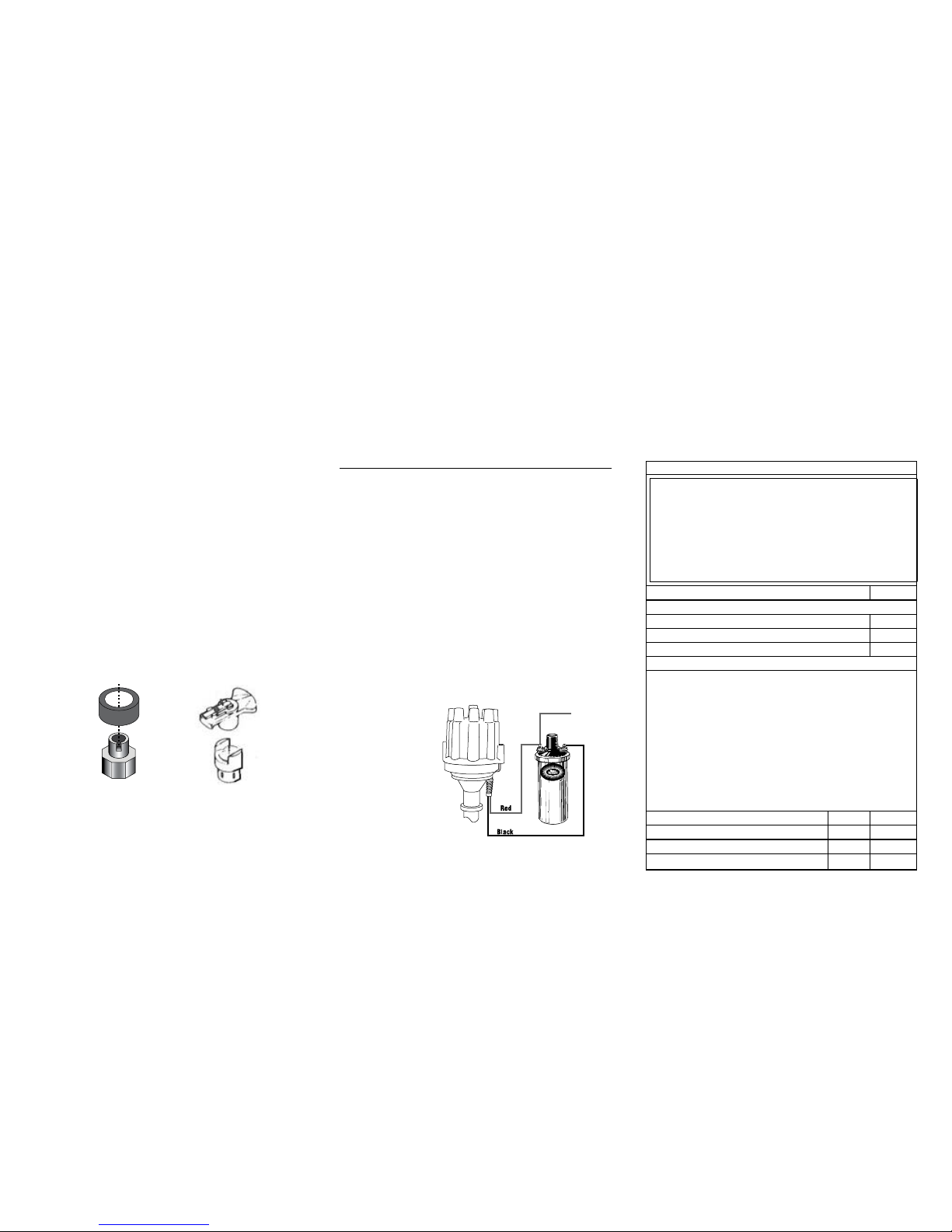
2. Attach the black Ignitor II wire to the negative coil terminal. Attach the red Ignitor II
wire to the positive coil terminal. (See Figure 3)
A. Recommended Installation: Many vehicles came equipped with ballast resistor or
resistance wire. To achieve optimum performance from the Ignitor II ignition system, we
recommend removal of these components.
• To remove a ballast resistor, (normally white ceramic blocks 3 to 4 inches long), dis
-
connect all wires on both ends of the ballast resistor. Remove the resistor from the
vehicle and splice the disconnected wires together at a single point.
• To remove a resistance wire, trace the coil power wire, which was previously con
-
nected to the positive coil terminal, back to the fuse block. Bypass this wire with a
12-gauge copper stranded wire.
B. Alternative Installation: The Ignitor II can also be installed in applications retaining
the ballast resistor or resistance wire.
• Attach the Ignitor II black wire to the negative coil terminal. Attach the Ignitor II red
wire to the ignition side of resistance, or any 12 volt ignition power source.
3. Check to insure that the
polarity is correct, and that
all connections are tight.
4. Re-connect the battery.
5. Perform the Power and
Ground tests. Refer to the
Power and Ground test
procedure.
6. Start the engine and allow
it to reach normal operat
-
ing temperature. Check
ignition timing, and adjust
to the desired setting.
+
-
To Ignition
FIGURE 3
(WITHOUT EXTERNAL RESISTOR)
POWER & GROUND TESTS
It is imperative that the power and grounds be checked as part of the installation
procedure. After installing the Ignitor module and the distributor and with the
distributor in the engine, use a digital multi-meter to measure the resistance from
the aluminum plate holding the module to battery (-), the net resistance must be
less than 0.2 ohms. (Set meter to lowest ohms setting). The net resistance is the
meter reading minus the resistance of the meter leads. If the net resistance is
greater than 0.2 ohms, the source of the faulty ground must be found and fixed.
Usually the source of the bad ground is easily found by holding one probe on an
original location and moving the second probe toward the static probe. Where the
resistance drops identifies the source.
Maximum resistance from Ignitor plate to battery negative terminal. 0.2 ohms
EXAMPLE:
Resistance from Ignitor plate to battery negative (-) terminal. 0.4 ohms
Resistance of meter leads 0.2 ohms
After subtracting meter lead resistance, your net resistance is: 0.2 ohms
VOLTAGE TEST
1. (Do not disconnect wires from Ignition coil). Place ignition switch in the “off” position.
2. Connect a jumper wire from negative (-) terminal of the coil to a good engine
ground.
3.Connect the voltmeter red lead to the positive (+) terminal of the coil and the black
lead to a good engine ground.
4.Turn the ignition switch to the “on” position and note voltage reading on the voltmeter. Quickly read the voltage and turn ignition “OFF”. Leaving ignition “ON” for an
extended period could result in permanent damage to the Ignitor.
5. SEE CHART BELOW FOR SPECIFICATIONS.
Note: Low voltage can be caused by poor connections, poor contacts in the
ignition switch, ballast resistor, and or a resistance wire in the wiring harness
(Factory Installed).
Minimum Maximum
Ignition Switch “ON” 8.0V N/A
Cranking 8.0V N/A
Engine Running N/A 16.0V
FIGURE 1 FIGURE 2
6. The Ignitor does not require any modifications to distributor. Therefore the
points, condenser, dust cap and hardware can be used as backup.
7. Clean all dirt and excess oil from the breaker plate and point cam.
8. Install the Ignitor II plate into the distributor housing.
• Line up hole or cutout on the Ignitor plate to the wire exit hole in the
distributor housing.
• 91548 kit only: Line up “X” mark on the Ignitor II plate to the wire exit hole
on distributor housing.
• 1585A kit only: Line up “O” mark on the Ignitor plate to the wire exit hole
on the distributor housing.
• Fasten the Ignitor plate into place using the original screws.
9. Insert wires through hole in the distributor housing and pull wire grommet
into place. CAUTION: Care must be taken to insure wires do not interfere
with moving parts.
10. Some magnet sleeves have green or blue tape, DO NOT REMOVE IT.
11. There are two types of magnet sleeves.
• Figure 1, Install magnet sleeve over distributor shaft, onto point cam.
Rotate sleeve until a slight locating position is felt before applying
pressure. With magnet sleeve lined up on point cam, press down firmly
insuring sleeve is fully seated.
• Figure 2, Install magnet sleeve over distributor shaft,
press rotor down
into the magnet sleeve and onto distributor shaft. NOTE: Rotor is indexed
to the sleeve by the locating ears, make sure rotor is completely seated
on distributor shaft. An o-ring may be included in the hardware kit. Install
the o-ring between the point cam and the magnet sleeve.
12. Install distributor cap. Make sure all spark plug wires are securely
attached. Warning!
DO NOT USE WITH SOLID CORE SPARK PLUG WIRES.
13. See wiring Instructions.
 Loading...