

Page 1
POWER & GROUND TESTS
It is imperative that the power and grounds be checked as part of the installation
procedure. After installing the Ignitor module and the distributor and with the
distributor in the engine, use a digital multi-meter to measure the resistance from
the aluminum plate holding the module to battery (-), the net resistance must be
less than 0.2 ohms. (Set meter to lowest ohms setting). The net resistance is the
meter reading minus the resistance of the meter leads. If the net resistance is
greater than 0.2 ohms, the source of the faulty ground must be found and fixed.
Usually the source of the bad ground is easily found by holding one probe on an
original location and moving the second probe toward the static probe. Where the
resistance drops identifies the source.
Maximum resistance from Ignitor plate to battery negative terminal. 0.2 ohms
EXAMPLE:
Resistance from Ignitor plate to battery negative (-) terminal. 0.4 ohms
Resistance of meter leads 0.2 ohms
After subtracting meter lead resistance, your net resistance is: 0.2 ohms
VOLTAGE TEST
1. (Do not disconnect wires from Ignition coil). Place ignition switch in the “off” position.
2. Connect a jumper wire from negative (-) terminal of the coil to a good engine
ground.
3.Connect the voltmeter red lead to the positive (+) terminal of the coil and the black
lead to a good engine ground.
4.Turn the ignition switch to the “on” position and note voltage reading on the voltmeter. Quickly read the voltage and turn ignition “OFF”. Leaving ignition “ON” for an
extended period could result in permanent damage to the Ignitor.
5. SEE CHART BELOW FOR SPECIFICATIONS.
Note: Low voltage can be caused by poor connections, poor contacts in the
ignition switch, ballast resistor, and or a resistance wire in the wiring harness
(Factory Installed).
Minimum Maximum
Ignition Switch “ON” 8.0V N/A
Cranking 8.0V N/A
Engine Running N/A 16.0V
LIMITED WARRANTY
Pertronix, Inc. Warrants to the original Purchaser of its solid-state ignition system
(product) that the Ignitor, magnet assembly and wiring (components) shall be free from defects
in material and workmanship for a period of (30) months from the date of purchase.
If within the period of the foregoing warranty Pertronix finds, after inspection, that the
product or any component thereof is defective, Pertronix will, at its option, repair such products
or component or replace them with identical or similar parts PROVIDED that within such period
Purchaser:
Promptly Notifies PerTronix, in writing, of such defects.
Delivers the defective products product or component to Per tronix (ATTN: Warranty) with proof
of purchase date; and
Has installed and used the product in a normal and Proper manner, consistent with Pertronix
printed instructions.
THE FORGOING LIMITED WARRANTY IS EXCLUSIVE AND IN LIEU OF ALL
OTHER WARRANTIES, WHETHER EXPRESSED OR IMPLIED, INCLUDING AND IMPLIED
WARRANTY OR MERCHANTABILITY OR FITNESS FOR A PURPOSE.
THE FURNISHING OF A REPAIR OR REPLACEMENT COMPONENTS SHALL
CONSTITUTE THE SOLE REMEDY OF PURCHASER AND THE SOLE LIABILITY OF
PerTronix WHETHER ON WARRANTY, CONTRACT
EVENT WILL PerTronix BE LIABLE FOR MONEY DAMAGES WHETHER DIRECT OR
CONSEQUENTIAL.
OR FOR NEGLIGENCE, AND IN NO
440 E. Arrow Highway,
San Dimas, CA. 91773
909-599-5955
www.pertronix.com
12-VOLT NEGATIVE GROUND INSTRUCTIONS
For Part Number: 91247
GENERAL INFORMATION
1. IMPORTANT: Read all instructions before starting installation.
2. DO NOT USE WITH SOLID CORE SPARK PLUG WIRES.
3. This kit is designed to fit N-Series Ford Tractors with front mount distributors.
4. Some modifications to the original distributor is necessary.
5.
The Ignitor II ignition can be used in conjunction with most ignition coils rated at
0.45 ohms or greater.
6. All external resistors must be removed to achieve optimum performance from the
Ignitor II ignition system.
7. The Ignitor II is compatible as a trigger for most electronic boxes.
8. See our website (www.pertronix.com) for the latest product information.
REMOVING THE DISTRIBUTOR.
1. TURN IGNITION SWITCH OFF OR DISCONNECT THE BATTERY.
2. Disconnect the coil power wire.
3. Remove the spark plug wires from the distributor cap.
4. Remove the coil by unsnapping the retainer bail.
5. Unsnap and remove the distributor cap.
6. Note the position of the rotor so that the distributor can be reinstalled in
the same position. Remove the rotor.
7. Remove the two bolts that hold the distributor to the block.
8. Remove the distributor.
REMOVING THE BREAKER PLATE & CONDENSER
1. Remove the breaker plate retaining ring.
2. Remove the breaker plate hold down screw.
3. Remove the condenser.
4. Remove the shim washer from the distributor shaft.
5. Remove the distributor shaft and advance mechanism.
6. Remove the condenser.
7. Check the distributor for cracks and excess wear.
MODIFYING THE DISTRIBUTOR.
1. To allow the Ignitor II wires to exit the distributor, the vent screen closest
to the coil retaining bail must be removed. If the distributor does not have
a vent, drill a 1/4” hole into the distirbutor housing at the location shown in
illustration B.
2. This is a good time to clean the distributor thoroughly. Make sure that no
metal debris is left in the distributor.
Page 2
3. Install the advance mechanism and the shaft back into the distributor.
IGNITOR II INSTALLATION.
1. Set the adapter plate into the distributor. Insert the provided hold down
stud through the plate and distributor housing.
2. Install the timing adjustment slide over the stud. Install the provided lock
nut.
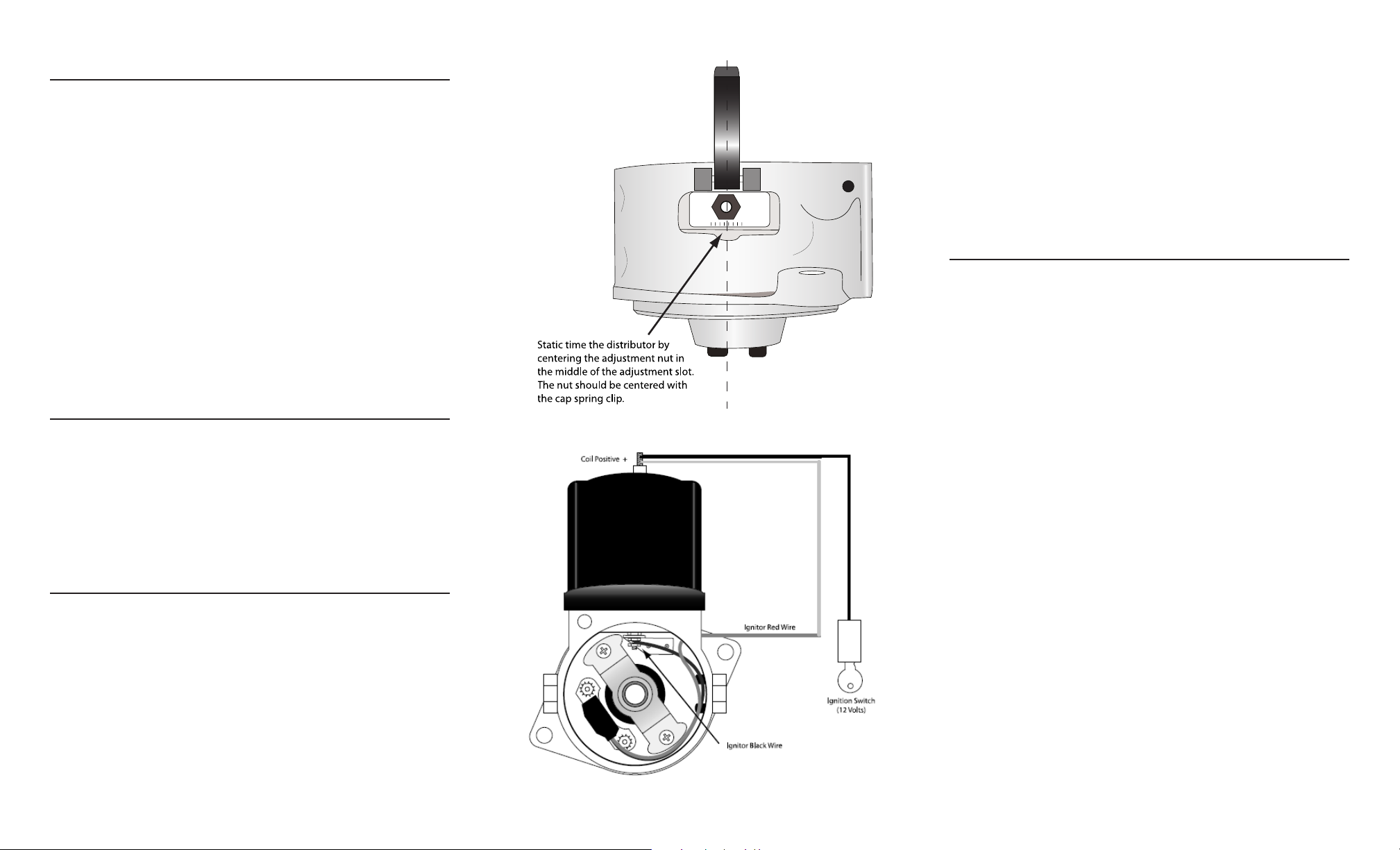
3. Static timing the distributor by positioning the plate so the the slide is
positioned in the middle of the adjustment slot. The adjustment nut should
be centered with the cap spring clip (See illustration B). Tighten the nut
once it is aligned properly.
4. Install the plate retaining ring. The flat portion of the ring should be placed
on the adjustment slot side of the distributor.
5. Install the Ignitor II module onto the mounting studs.
6. Tighten the module into place with the hardware provided.
7. Attach the black Ignitor II wire to the coil negative contact stud mounted on
the plate. Tighten the wire down with the provided nut. (See illustration C).
8. Insert the red wire through the hole that was made in the distributor body.
9. Install the magnet sleeve onto the point cam.
10. Install the shim washer onto the distributor shaft.
11. Install the shaft support bracket. Spin the distributor shaft to align the
bracket and tighten in place with the 8-32 screws provided.
DISTRIBUTOR INSTALLATION.
1. Install the rotor.
2. Turn the rotor to the position that was noted prior to the removal of the
distributor.
3. Place distributor into block and fasten in place with the original mounting
bolts. Note: Do not force the distributor onto place. Check to make sure
that dive tang is properly aligned.
4. Instal the distributor cap.
5. Install the coil and coil retaining bail.
6. Install the spark plug wires.
WIRING.
1. Attach the Ignitor red wire and the Ignition wire to the coil positive
terminal.
COMMON QUESTIONS AND ANSWERS
Q. The engine will not star t or runs rough. What is the problem?
A. Perform Power and Ground Checks. Check all connections to insure that they are tight, and in
the proper location. Check all grounds; if a distributor ground wire was removed make sure that it
was reattached properly. Make sure that the red Ignitor II wire is supplied with a full 12 volts. The
Ignitor II is designed to sense high current levels, and shut off before damage occurs. Check all
wires for shorts, correct polarity and that the ignition coil’s primary resistance level is acceptable.
Q. . The vehicle will start, but then die. After waiting it will start again. What is wrong?
A. Perform Power and Ground Checks. The Ignitor II may have a “Low Voltage Problem.” If the
voltage supplied to the red Ignitor II wire is insufficient, the system may run for a period of time,
and then shut down as the voltage drops due to engine heat. The period may vary from minutes to
hours depending on available voltage and wiring condition. To remedy this condition refer to steps
2-4 of the wiring instructions.
Q. How do I check for a “Low Voltage Problem” or determine if I am getting adequate voltage?
A. Perform Power and Ground Checks. Also, to quickly test for a “Low Voltage Problem” or for
adequate voltage, remove the Ignitor II red wire from the coil positive terminal. Attach a jumper
wire from the battery positive terminal to the Ignitor II red wire. Tr y to start the vehicle. If the
vehicle starts with this test refer to steps 2-4 of the wiring instructions for further information.
Q. How do I check my coil for primary resistance?
A. Remove all wires from the coil. Set the ohmmeter to the lowest scale. Attach one lead of the
meter to the positive coil terminal. Attach the other lead to the negative coil terminal.
Q. May I modify the length of the wires?
A. Yes, you may cut the wires to any length your application requires. You may also add lengths of
wire if needed (20-gauge). Make sure that all wire splices are clean and the connections are tight.
Q. Will the Ignitor II work with aftermarket capacitive discharge boxes?
A. Yes, the Ignitor II is compatible with most CD boxes in the same respect as points. Use the CD
box wiring instructions for point systems and treat the Ignitor II black wire as a point wire. The
Ignitor II red wire should be attached to the 12-volt power source.
Q. Will the electronic shift assist in an OMC boat work with the Ignitor II?
A. The Ignitor II will work with all OMC stern-drive applications, when our “diode fix” is used. If
you’ve purchased a kit that didn’t include the “diode fix” diagram, call our tech line.
Q. How can I receive additional help?
A. Check our web site for current trouble shooting tips and up to date technical information. Log on
to www.pertronix.com. You may also contact our tech line at (909-547-9058)
 Loading...