

Page 1
COMMON QUESTIONS AND ANSWERS
Q. The engine will not start or runs rough. What is the problem?
A. Perform Power and Ground Checks. Check all connections to insure that they are
tight, and in the proper location. Check all grounds; if a distributor ground wire was
removed make sure that it was reattached properly. Make sure that the red Ignitor II
wire is supplied with a full 12 volts. The Ignitor II is designed to sense high current
levels, and shut off before damage occurs. Check all wires for shorts, correct polarity
and that the ignition coil’s primary resistance level is acceptable.
Q. . The vehicle will start, but then die. After waiting it will start again. What is wrong?
A. Perform Power and Ground Checks. The Ignitor II may have a “Low Voltage Problem.”
If the voltage supplied to the red Ignitor II wire is insufficient, the system may run for a
period of time, and then shut down as the voltage drops due to engine heat. The period
may vary from minutes to hours depending on available voltage and wiring condition. To
remedy this condition refer to steps 2-4 of the wiring instructions.
Q. How do I check for a “Low Voltage Problem” or determine if I am getting adequate
voltage?
A. Perform Power and Ground Checks. Also, to quickly test for a “Low Voltage Problem”
or for adequate voltage, remove the Ignitor II red wire from the coil positive terminal.
Attach a jumper wire from the battery positive terminal to the Ignitor II red wire. Try
to start the vehicle. If the vehicle star ts with this test refer to steps 2-4 of the wiring
instructions for further information.
Q. How do I check my coil for primary resistance?
A. Remove all wires from the coil. Set the ohmmeter to the lowest scale. Attach one
lead of the meter to the positive coil terminal. Attach the other lead to the negative coil
terminal.
Q. May I modify the length of the wires?
A. Yes, you may cut the wires to any length your application requires. You may also add
lengths of wire if needed (20-gauge). Make sure that all wire splices are clean and the
connections are tight.
Q. Will the Ignitor II work with aftermarket capacitive discharge boxes?
A. Yes, the Ignitor II is compatible with most CD boxes in the same respect as points.
Use the CD box wiring instructions for point systems and treat the Ignitor II black wire
as a point wire. The Ignitor II red wire should be attached to the 12-volt power source.
Q. Will the electronic shift assist in an OMC boat work with the Ignitor II?
A. The Ignitor II will work with all OMC stern-drive applications, when our “diode fix” is
used. If you’ve purchased a kit that didn’t include the “diode fix” diagram, call our tech
line.
Q. How can I receive additional help?
A. Check our web site for current trouble shooting tips and up to date technical
information. Log on to www.pertronix.com. You may also contact our tech line at
(909-547-9058)
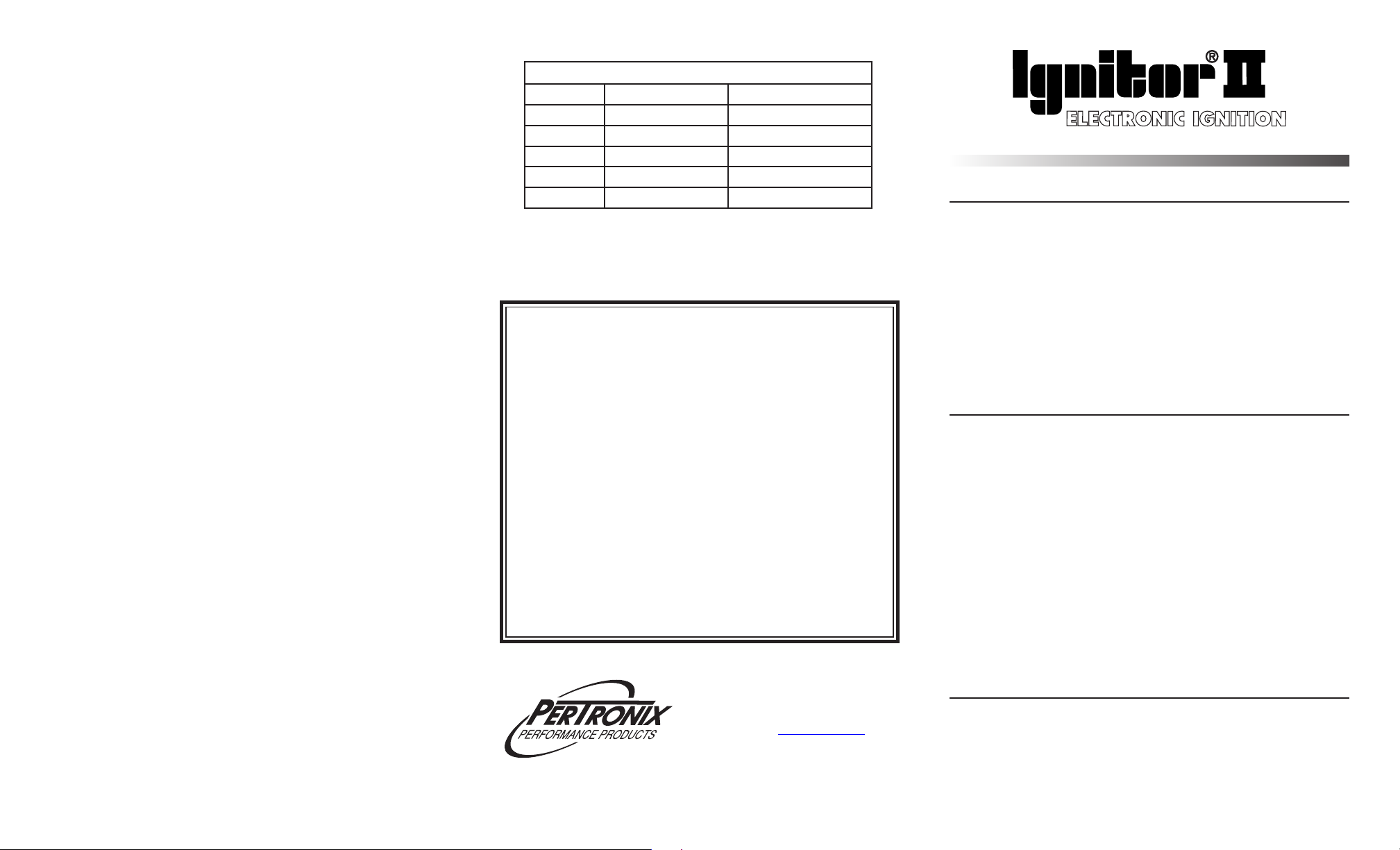
RECOMMENDED FLAME-THROWER COILS
COIL # PRIMARY RESISTANCE DESCRIPTION
45001 0.6 CHROME - OIL FILLED
45011 0.6 BLACK - OIL FILLED
45111 0.6 EPOXY
60104 0.45 HV
LIMITED WARRANTY
Pertronix, Inc. Warrants to the original Purchaser of its solid-state ignition system
(product) that the Ignitor, magnet assembly and wiring (components) shall be free from defects
in material and workmanship for a period of (30) months from the date of purchase.
If within the period of the foregoing warranty Pertronix finds, after inspection, that
the product or any component thereof is defective, Pertronix will, at its option, repair such
products or component or replace them with identical or similar parts PROVIDED that within
such period Purchaser:
1. Promptly Notifies PerTronix, in writing, of such defects.
2. Delivers the defective products product or component to Pertronix (ATTN: Warranty)
with proof of purchase date; and
3. Has installed and used the product in a normal and Proper manner, consistent with
Pertronix printed instructions.
THE FORGOING LIMITED WARRANTY IS EXCLUSIVE AND IN LIEU OF ALL
OTHER WARRANTIES, WHETHER EXPRESSED OR IMPLIED, INCLUDING AND IMPLIED
WARRANTY OR MERCHANTABILITY OR FITNESS FOR A PURPOSE.
THE FURNISHING OF A REPAIR OR REPLACEMENT COMPONENTS SHALL CONSTITUTE
THE SOLE REMEDY OF PURCHASER AND THE SOLE LIABILITY OF PerTronix WHETHER
ON WARRANTY, CONTRACT
BE LIABLE FOR MONEY DAMAGES WHETHER DIRECT OR CONSEQUENTIAL.
OR FOR NEGLIGENCE, AND IN NO EVENT WILL PerTronix
440 E. Arrow Highway, San Dimas, CA. 91773
909-599-5955 www.pertronix.com
12-VOLT NEGATIVE GROUND INSTRUCTIONS
For Part Number: 91181, 91141, 91164
GENERAL INFORMATION
1. IMPORTANT: Read all instructions before star ting installation.
2. DO NOT USE WITH SOLID CORE SPARK PLUG WIRES.
3. DISTRIBUTOR MUST BE REMOVED TO INSTALL IGNITOR KIT.
4. The Lobe sensor Ignitor II is designed specifically for the application and distributor
numbers that are listed in the application guide. Any modification to this component
will void the warranty.
5. The Lobe Sensor Ignitor II does not require a magnet sleeve to trigger the module.
6.
The Ignitor II ignition can be used in conjunction with most ignition coils rated at
0.45 ohms or greater.
7. All external resistors must be removed to achieve optimum performance from the
Ignitor II ignition system.
8. The Ignitor II is compatible as a trigger for most electronic boxes.
9. See our website (www.pertronix.com) for the latest product information.
DISTRIBUTOR DISASSEMBLY
1. PRIOR TO INSTALLATION TURN IGNITION SWITCH OFF
OR DISCONNECT THE BATTERY
2. Disconnect point wire from negative (-) coil terminal.
3. Remove distributor cap.
Examine cap for wear or damage. Replace as needed.
4. REMOVE DISTRIBUTOR FROM ENGINE. Note position of
rotor before removing distributor.
5. Remove rotor.
Examine rotor for wear or damage. Replace as needed.
6. Remove point wire from distributor point assembly. Remove points wire
from distributor.
7. Remove breaker point assembly and condenser. Retain screws and
washers to install Ignitor module.
8. Remove point wire from negative (-) terminal of the coil.
9. The Ignitor does not require any modification to the distributor. Therefore
the points, condenser and hardware can be used as backup.
10. Clean all dirt and excess oil from the breaker plate and point cam.
IGNITOR II INSTALLATION
11. Install magnet ring by slipping over advance weight assembly and
inserting the two threaded 6/32 studs up through the two 10-32 threaded
holes where screws that held rotor were removed. (See figures B & C).
12. Install rotor (we recommend a new rotor) over the 6/32 studs and secure
with 6/32 kep nuts and flat washers. These flat washers are the two thick
ones. The thinner spacer washers are furnished for adjusting air gap. Do
Do not disconnect spark plug wires from cap.
Page 2
not tighten these kep nuts at this time.
13. Install Ignitor module in the same holes where the points were. NOTE:
Dual point distributors require the module to be mounted in the place
of the leading point. Use the screws that held the point assembly to the
breaker plate. Screws should be finger tight at this point.
Caution - BE sure that magnet ring is seated against the advance mechanism
plate and the module is seated against breaker plate. The shaft must be
seated in the lowest position when measuring gap.
14. You will be trying to get an air gap between approximately 0.010” at the
low end and no more than 0.060” at the high end. With the distributor
shaft pulled down, rotate the shaft and make sure the magnet ring does
not rub against the Ignitor module. If it happens to rub against the Ignitor
module, carefully bend the Ignitor module bracket down until it does not
rub. Bend with pliers at the bracket so as not to loosen the rivets. If there
is a gap, rotate the distributor shaft and measure the largest air gap
between the face of the magnet ring and the face of the Ignitor module. If
you have an Oldsmobile, and the largest gap is more than 0.060”, go to
step #14. Otherwise, continue with the next step.
15. If the gap is greater than 0.060” record what it is. The gap is adjusted by
installing thin washers over the 6/32 studs between the magnet ring and
advance mechanism plate. It is necessary to remove module, rotor, and
ring to do this. The washers are 0.032” thick. From the gap measurement
recorded, Calculate how many washers are needed to bring the lowest
part of the magnet ring to approximately 0.010” from the Ignitor module.
Install washers on each side. if you have an Oldsmobile, go to step #14.
Otherwise, go to the next step.
16. Now push the distributor shaft up and rotate. If the highest point between
the Ignitor module and the ring is greater than 0.060”, you will need to
place shims between the gear and distributor housing to prevent the gap
from going over 0.060”.
17. Reinstall magnet ring, rotor and module. Secure in position. Double check
gap. If readjustment is necessary, follow the above procedure.
18. Instal the rubber grommet from the kits hardware into the large hole on
the bottom of the distributor housing.
19. Place both the red and black wires carefully through the grommet.
20. Attach terminals to the ends of both wires. You may cut wires to your
desired length if they are too long.
21. Reinstall distributor in vehicle, making sure rotor is in same position as
when removed.
22. Place distributor cap on distributor. All spark plugs wires should be
seated securely.
23. See Wiring Instructions.
WIRING INSTRUCTIONS
Recommended Installation: Many vehicles came equipped with ballast resistor or
resistance wire. To achieve optimum performance from the Ignitor II ignition system, we
recommend removal of these components.
• To remove a ballast resistor, (normally white ceramic blocks 3 to 4 inches long), dis-
connect all wires on both ends of the ballast resistor. Remove the resistor from the
Figure A
Figure B
vehicle and splice the disconnected wires together at a single point.
• To remove a resistance wire, trace the coil power wire, which was previously con-
nected to the positive coil terminal, back to the fuse block. Bypass this wire with a
12-gauge copper stranded wire.
The Ignitor II ignition can be used in conjunction with most ignition coils rated at 0.45
ohms or greater. For optimum performance purchase and install the Flamethrower II
high performance coil. See back page for coil recommendations.
• DO NOT USE SOLID CORE SPARK PLUG WIRES.
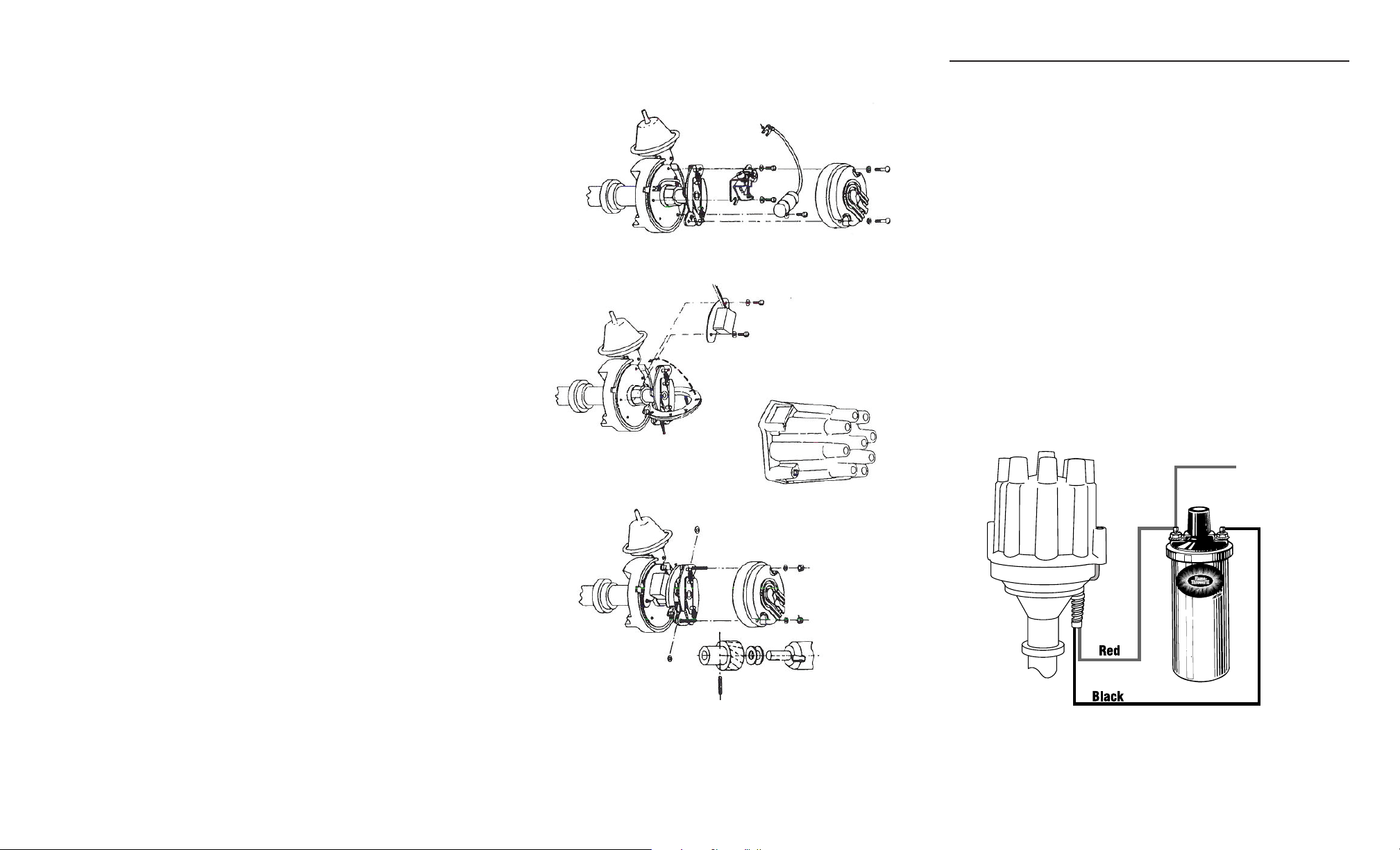
1. Attach the black Ignitor II wire to the negative (-) coil terminal. (See Figure 3)
2. Attach the red Ignitor II wire to the positive (+) coil terminal. (See Figure 3)
3. Check to insure that the polarity is correct, and that all connections are tight.
4. Re-connect the battery.
5. Start the engine and allow it to reach normal operating temperature. Check igni-
tion timing, and adjust to the desired setting.
To Ignition
+
Figure C
FIGURE 3
(WITHOUT EXTERNAL RESISTOR)
-
 Loading...