

Page 1
Installation Instructions
Part # Ohms Applications
60103 0.32 Ignitor III, Ignitor II, HEI, TFI, CD (with current limiting circuity)
PARTS INCLUDED IN THIS PACKAGE:
1 coil
4 #10 sheet metal screws
4 10-32 machine screws and nuts
2 10-32 coil terminal nuts
2 ring terminals
1 coil wire boot
1 coil wire terminal
0015-008704
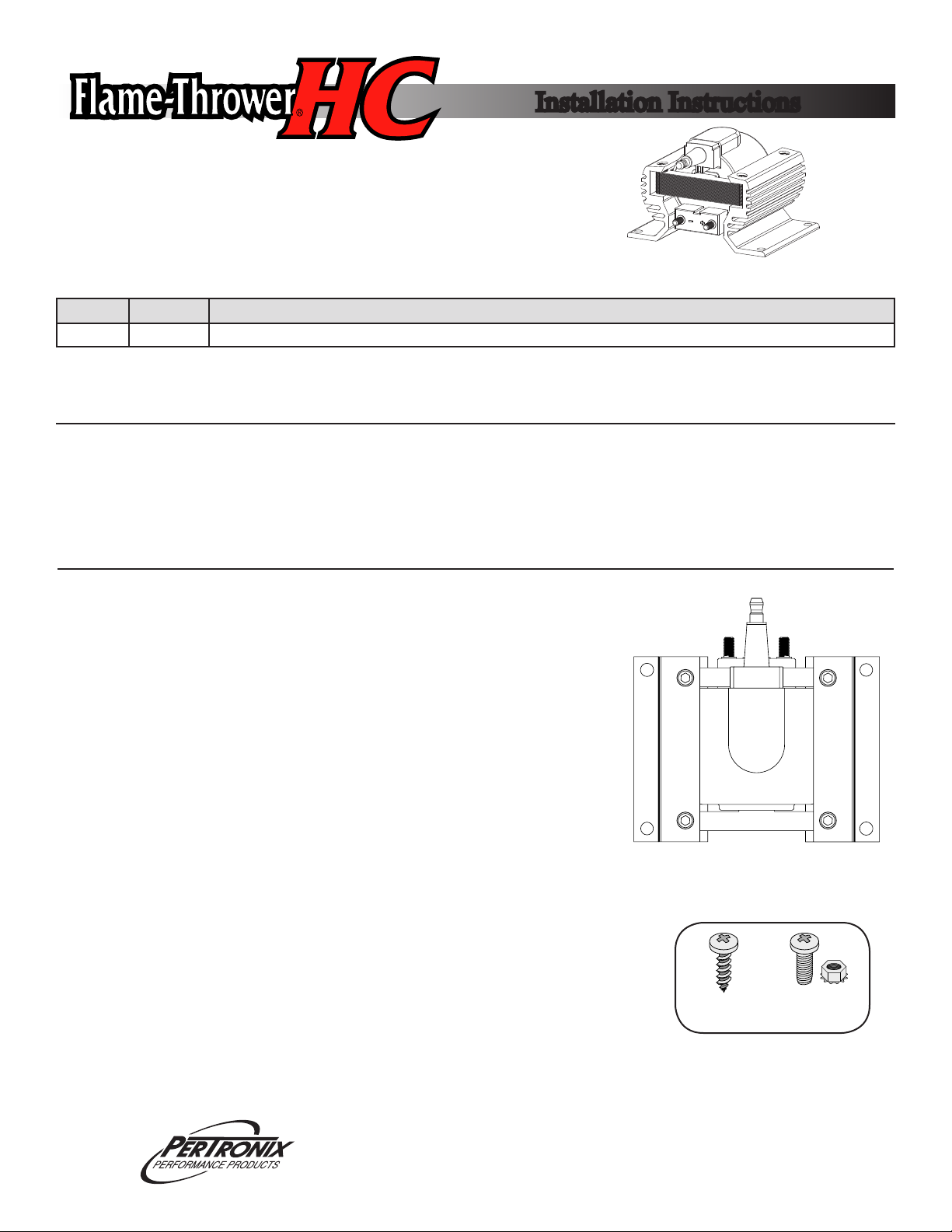
MOUNTING THE COIL
1. Turn the ignition switch off and disconnect the battery negative cable.
2. Remove the coil high tension wire from the coil tower.
3. Label and remove all wires from the positive and negative coil terminals.
4. Remove the existing coil.
5. The Flame-Thrower HC coil can be mounted in a variety of positions and
locations. Choose a at location that is away from direct heat and mechanical linkage yet is relatively close to the distributor. Common locations
would include a fenderwell or rewall.
6. Verify that the coil high tension and primary ignition wires reach the chosen
mounting location.
7. Hold the coil in position and mark the four mounting hole points with a pen
or transfer punch.
8. The Flame-Thrower HC coil comes with all the necessary hardware to
securely mount it. Machine screws and kep nuts should be used when the
back side of the mounting location is accessible. Use the sheet metal screws
for blind mounting locations.
9. Before you begin drilling holes, check to be sure where you are drilling will
not result in damage.
10. Blind mounting Flame-Thrower HC coil with sheet metal screws is simple. Each
screw has a self taping point. Using a power driver, position the screw onto each of
the marked points and tighten the coil into place.
11. When mounting the coil with the machine screws, use a 1/4” bit to drill a hole in
each of the mounting points. Apply a drop of thread lock to each the screw threads
and install the provided kep nuts. Tighten the coil into place.
# 10 Sheet
Metal Screw
10-32 Machine
Screw
440 East Arrow Highway • San Dimas, CA 91773 • 909-599-5955 • www.pertronix.com
Page 2
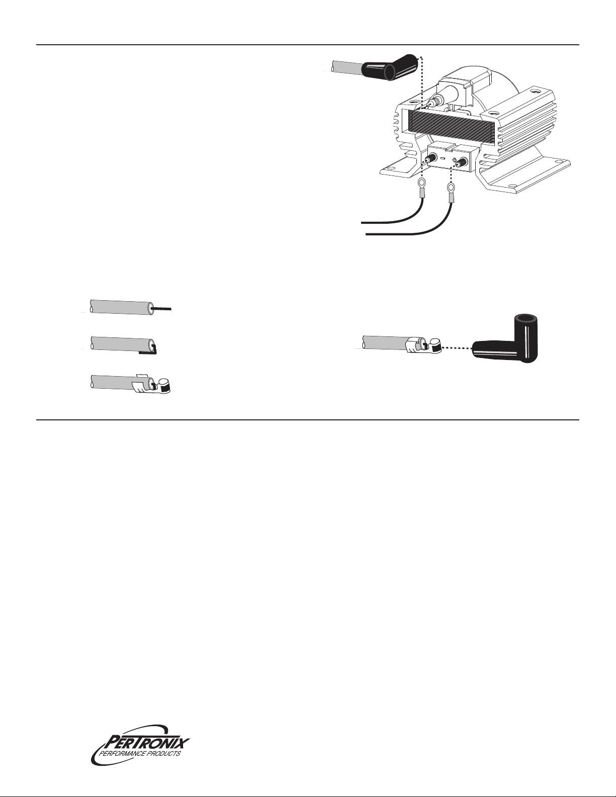
ATTACHING THE WIRES
1. Route the coil high tension wire from the distributor to
the coil. The coil wire should positively snap onto the
coil terminal. If your coil wire has the incorrect terminal
end, replace it with the provided terminal and boot.
(See Step #4)
2. Connect all of the wires that were removed from the
negative coil terminal of the old coil to the negative
terminal of the Flame-Thrower HC coil. If necessary, use
the provided new ring terminals.
3. Connect the wires that were removed from the positive
coil terminal of the old coil to the positive terminal of the
Flame-Thrower HC coil. If necessary, use the provided
new ring terminals.
4. If the coil wire has a male stye terminal, you will need
to replace it with the provided female terminal. Follow
these steps:
To distributor
cap
To distributor
trigger
To ignition
switch
-
+
A. Strip 3/4” of the insulation to expose the conductor.
Be extra careful not to cut or damage the core.
B. Fold the conductor back onto the wire.
C. Slide the terminal into place.
D. Crimp the terminal into place with an ignition wire
crimping tool. Apply a small amount of dielectric
grease to the terminal. Spray the inside of
the boot with a silicone spray and slide
it into place.
FINAL CHECKS
1. Check all connections for correctness.
2. Re-attach the battery if disconnected.
3. In performance applications, the spark gap may be increased to take advantage of the extra energy, produced by the
Flame-Thrower HC coil. Since PerTronix cannot test every conguration, the end user must determine what spark
plug gap works best for their application.
LIMITED WARRANTY
PerTronix, Inc. warrants to the original Purchaser of its Flame-Thrower products that the product shall be free from defects in material and
workmanship (normal wear and tear excluded) for a period of 90 days from the date of purchase. If within the period of the foregoing warranty
PerTronix nds, after inspection, that the product or any component thereof is defective, PerTronix will, at its option, repair such products or
component or replace them with identical or similar parts PROVIDED that within such period Purchaser:
1. Promptly noties PerTronix, in writing, of such defects.
2. Delivers the defective products product or component to PerTronix (Attn: warranty) with proof of purchase date; and
3. Has installed and used the product in a normal and proper manner, consistent with PerTronix printed instructions
THE FOREGOING LIMITED WARRANTY IS EXCLUSIVE AND IN LIEU OF ALL OTHER WARRANTIES, WHETHER EXPRESS
OR IMPLIED, INCLUDING ANY IMPLIED WARRANTY OR MERCHANTABILITY OR FITNESS FOR A PARTICULAR PURPOSE.
THE FURNISHING OF A REPAIR OR REPLACEMENT COMPONENT OR COMPONENTS SHALL CONSTITUTE THE SOLE
REMEDY OF PURCHASER AND THE SOLE LIABILITY OF PerTronix WHETHER ON WARRANTY, CONTRACT OR FOR NEGLIGENCE, AND IN NO EVENT WILL PerTronix BE LIABLE FOR MONEY DAMAGES WHETHER DIRECT OR
CONSEQUENTIAL.
440 East Arrow Highway • San Dimas, CA 91773 • 909-599-5955 • www.pertronix.com
 Loading...