

Page 1
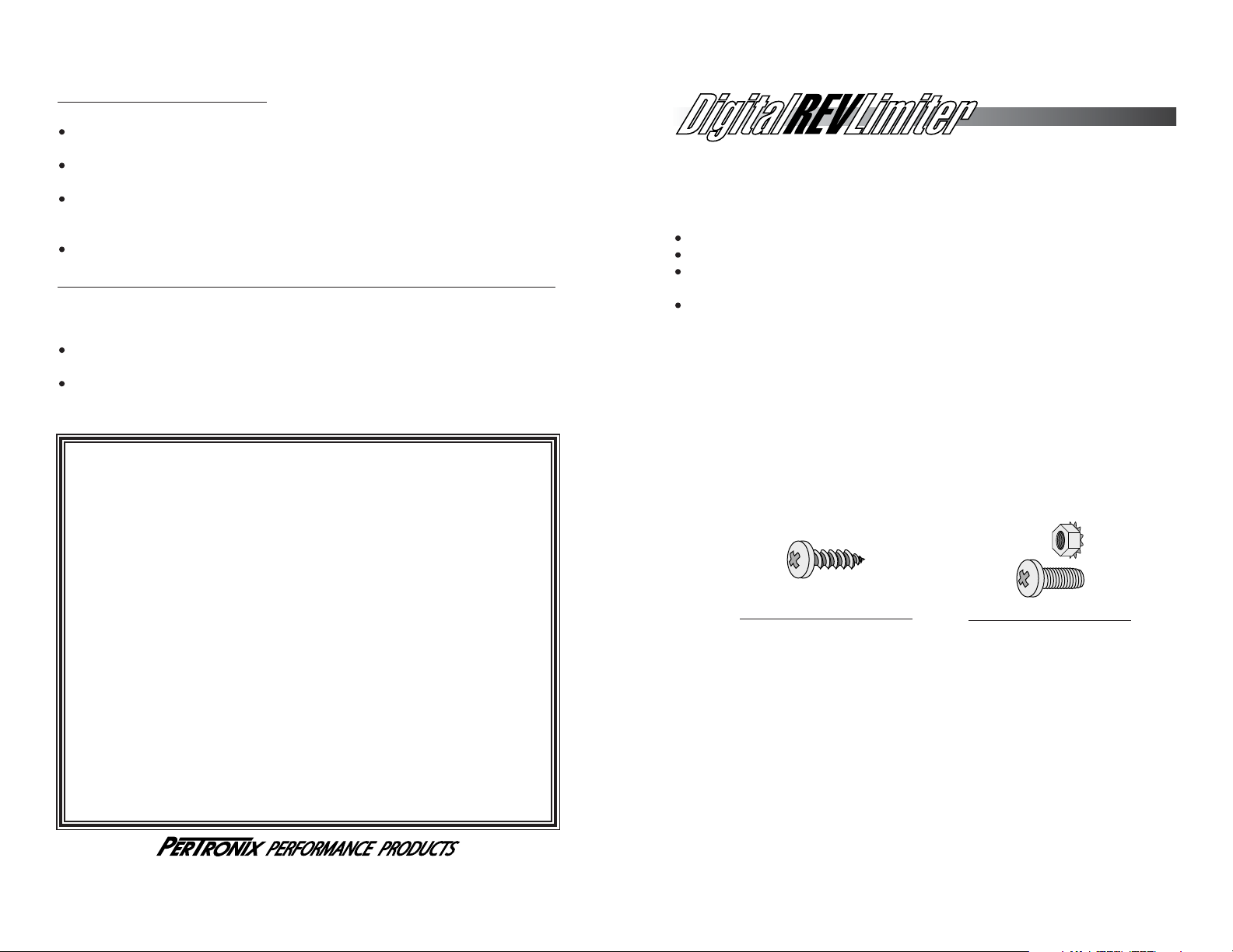
8-32 x 5/8 Machine Screw
Use a #29 drill bit (.136”)
for screw hole.
#8 x 3/4 Sheet Metal Scre
w
Use a #31 drill bit (.120”)
for screw hole.
Installation Instructions
GENERAL INFORMATION
Read all instructions before beginning installation
The Digital Rev Limiter is for use on 4, 6 and 8 cylinder, even fire engines.
Compatible systems include 12-volt negative ground, inductive type, single
coil applications. (Not for use with Capacitive Discharge Systems)
Disconnect the battery before installation.
MOUNTING INSTRUCTIONS
1. Choose a place to mount the rev limiter that is reasonably flat. Keep the
rev limiter away from direct heat, excessive vibration and areas susceptible
to wet conditions.
2. Position the rev limiter in the desired mounting position. Use the rev limiter
as a template and mark the four mounting positions.
3. Choose the mounting hardware type that best suits your application.
Note: Sheet metal screws can be used when the back side of the
mounting surface is not accessible. Machine screws should be used when
both sides of the mounting surface are accessible.
0018-00881012/02
LIMITED WARRANTY
PerTronix Inc. warrants to the original Purchaser of its Digital Rev Limiter
product that the product shall be free from defects in material and workmanship
(normal wear and tear excluded) for a period of 12 months from the date of
purchase.
If within the period of the foregoing warranty PerTronix finds, after inspection,
that the product or any component thereof is defective, PerTronix will, at its option,
repair such product or component or replace them with an identical or similar product or component PROVIDED that within such period Purchaser:
1. Promptly notifies PerTronix, in writing, of such defects.
2. Delivers the defective product or component to
PerTronix (Attn: Warranty) with proof of purchase date; and
3. Has installed and used the product in a normal and proper
manner, consistent with PerTronix printed instructions.
THE FOREGOING LIMITED WARRANTY IS EXCLUSIVE AND IN LIEU OF
ALL OTHER WARRANTIES, WHETHER EXPRESS OR IMPLIED, INCLUDING ANY
IMPLIED WARRANTY OR MERCHANTABILITY OR FITNESS FOR A
PARTICULAR PURPOSE.
THE FURNISHING OF A REPAIR OR REPLACEMENT COMPONENT OR
COMPONENTS SHALL CONSTITUTE THE SOLE REMEDY OF PURCHASER AND
THE SOLE LIABILITY OF PerTronix WHETHER ON WARRANTY, CONTRACT OR
FOR NEGLIGENCE, AND IN NO EVENT WILL PerTronix BE LIABLE FOR MONEY
DAMAGES WHETHER DIRECT OR CONSEQUENTIAL.
440 East Arrow Highway
San Dimas, CA 91773
909-599-5955
www.pertronix.com
WIRING THE DIGITAL REV LIMITER
There are two types of systems which the Digital Rev Limiter can be
configured for. These are categorized as HEI and Non-HEI systems. HEI
systems are defined as; Systems which have current limiting circuitry. Non-HEI
systems include all other inductive type single coil ignitions. Determine which
system you have and follow the corresponding wiring instructions. Remember to
reconnect the battery after the installation is completed.
TROUBLE SHOOTING TIPS
The Re
v Limiter does not work.
Test for operation between each step.
Check that all connections are correct. The black wire must be well
grounded and to a clean contact or surface.
Check to make sure the switches are in the correct position. Rotate the
switches back and forth then back to the proper setting.
Using a voltmeter set to 0-20 volts AC, place one lead of the meter to the
white rev limiter wire, and the other lead to a good engine ground. Start the
engine. The meter should read 2.5 volts with a tolerance of .2 volts.
Swap the yellow and orange wire. Remember to isolate the unused wire.
My tac
hometer is inaccurate or doesn’t work after installing the rev limiter.
Due the the accuracy of our Digital Rev Limiter, non-calibrated tachometers may
not exactly match the rev limit. If the tachometer is grossly inaccurate, or does
not operate at all, follow the steps below.
Check that all connections are correct. The black wire must be well
grounded and to a clean contact or surface.
Locate the original tachometer trigger wire. Disconnect it from it’s current
position and attach it to the rev limiter white wire.
Page 2

BLACK
ORANGE
YELLOW
RED
WHITE
TACH
OUTPUT
COIL
NEGATIVE
GROUND
NOT
USED
IGNITION
SWITCH
OR
COIL
BLACK
ORANGE
YELLOW
RED
WHITE
TACH
OUTPUT
COIL NEGATIVE OR
(TACH TERMINAL)
GROUND
NOT
USED
IGNITION SWITCH
OR COIL
ORIGINAL
IGNITION
SWITCH WIRE
ORIGINAL
TACH WIRE
Non-HEI type systems.
(FIGURE 1)
1. Attach the BLACK wire to a good engine ground. Make sure to remove
any dirt or paint beforehand.
2. Attach the RED wire to a 12 volt power source controlled by the ignition
switch.
3. Attach the YELLOW wire to the coil’s negative terminal.
4. The ORANGE wire is not used for Non-HEI type systems. Use the provided
end splice to isolate this wire.
5. The WHITE wire is a tachometer output, compatible with most modern
tachometers.
HEI
type systems. (FIGURE 2)
1. Attach the BLACK wire to a good engine ground. Make sure to remove any
dirt or paint before hand.
2. Attach the RED wire to a 12 volt power source controlled by the ignition
switch. On GM HEI applications remove the original ignition switch wire
from the terminal marked “BAT” on the coil cover. Plug the provided adapter
harness onto this terminal and then reconnect the original ignition switch
wire. Attach the RED wire to the open position on the adapter harness
3. Attach the ORANGE wire to the coil’s negative terminal. On GM HEI
applications plug the ORANGE wire onto the terminal marked “TACH” on
the coil cover. If the terminal is currently used, remove the wire, plug the
provided adapter harness onto the terminal and then reconnect the wire.
Attach the ORANGE wire to the open position on the adapter harness.
4. The YELLOW wire is not used for HEI type systems. Use the provided
end splice to isolate this wire.
5. The WHITE wire is a tachometer output, compatible with most modern
tachometers.
SETTING DIGITAL REV LIMITER
All settings can be done externally through the rotary switches on the front of
the rev limiter. A white dot on the rotary portion of the switch indicates the
switch position. Use a small flat blade screw driver to make adjustments.
1. Rotate the cylinder selection switch to the proper cylinder number for your
application. The white dot on the face of the switch should point to the
appropriate cylinder number. A slight indentation should be felt as the
switch is turned. This signifies proper switch alignment. Note: The Digital
Rev Limiter will only operate in 4, 6 and 8 cylinder modes.
2. The Digital Rev Limiter is not designed to be used as a governor. If the limit
is set too low, and engine RPM is allowed to push up against the rev limit,
failure to the Digital Rev Limiter or engine may result. Choose a desired rev
limit. The Digital Rev Limiter has a 100 RPM
resolution. This means that the rev limit can be
set between 100 and 9900 in increments of 100
RPM. A typical limit would be 5500 RPM. In this
case the 1000 switch is set to 5, and the 100
switch set to 5. By turning both switches to 0,
the rev limiter is rendered non-operational.
(FIGURE 1)
NON-HEI SYSTEMS
HEI SYSTEMS
(FIGURE 2)
 Loading...