

Page 1
0018-008811 12/13
Installation Instructions
GENERAL INFORMATION
• Read all instructions before beginning installation
• For use on 4, 6 and 8 cylinder, even fire engines.
• Compatible systems include 12-volt negative ground, inductive type, single coil applications.
• Do not use with solid core spark plug wires.
• Disconnect the battery before installation.
MOUNTING INSTRUCTIONS
1. Choose a place to mount the Second Strike box that is reasonably flat. Keep it away from direct heat, excessive
vibration and areas susceptible to wet conditions.
2. Position the Second Strike in the desired mounting position. Use the box as a template and mark the four mounting
points.
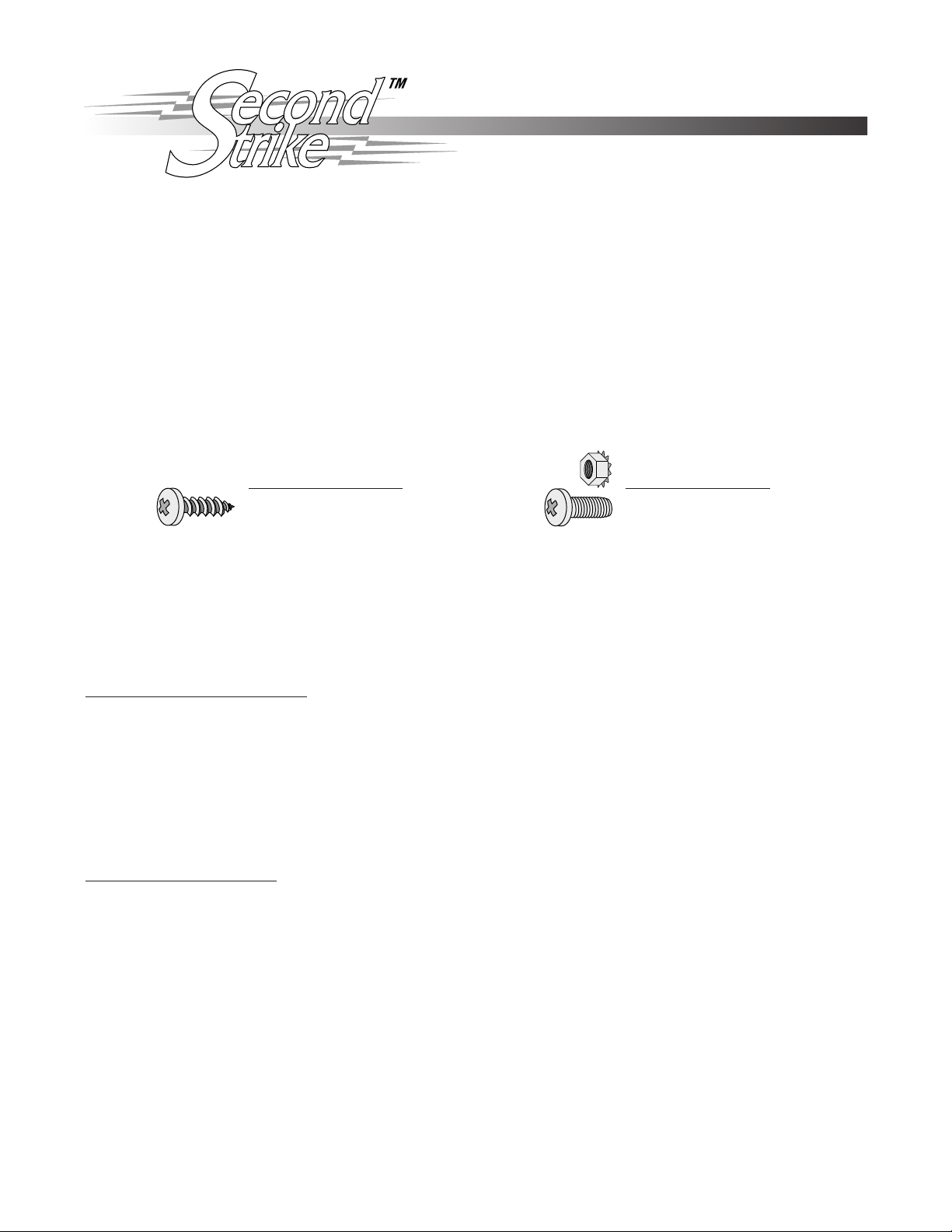
3. Choose the mounting hardware type that best suits your application. NOTE: Sheet metal screws can be used when the
back side of the mounting surface is not accessible. Machine screws should be used when both sides of the mounting
surface are accessible.
#8 x 3/4 Sheet Metal Screw
Use a #31 drill bit (.120”) for
screw hole.
8-32 x 5/8 Machine Screw
Use a #29 drill bit (.136”) for
screw hole.
WIRING THE SECOND STRIKE
There are two types of systems which the Second Strike can be configured for. These are categorized as HEI and NonHEI systems. Determine which system you have and follow the corresponding wiring instructions below. Wires can be shortened or lengthened to the desired length. Use the proper gauge wire when lengthening and make sure all connections are
crimped tight or soldered, and insulated. Wires not used should also be insulated. Remember to reconnect the battery after
the installation is completed.
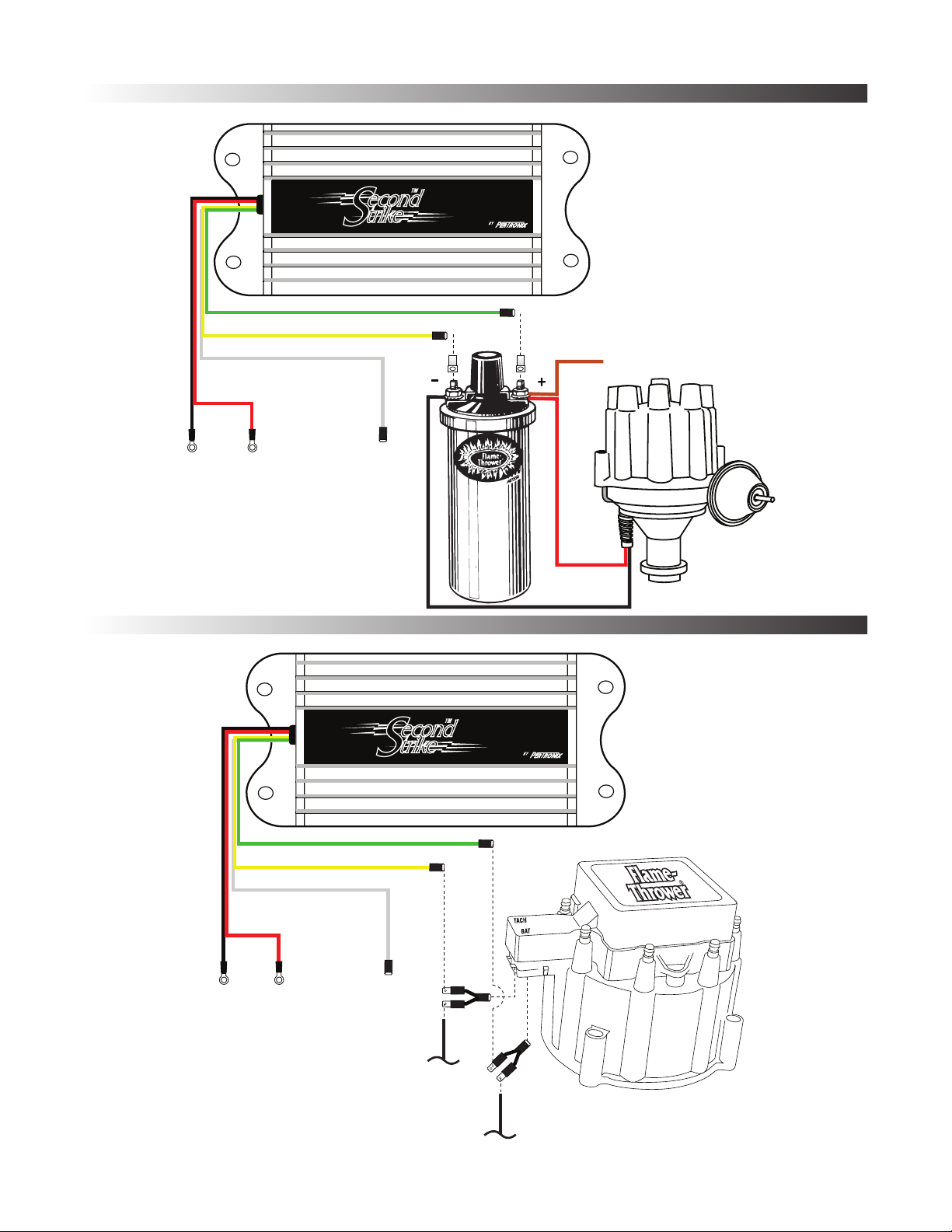
Non-HEI type systems. (FIGURE 1)
1. Attach the BLACK wire to a good engine ground or battery negative terminal. Make sure the connection is free of dirt,
grease and paint.
2. Attach the RED wire to the positive battery terminal or positive terminal of the starter solenoid.
3. Attach the GREEN wire to a 12 volt power source controlled by the ignition switch. The coil positive terminal can be
used as a power source as long as it provides a non-resisted 12 volts.
4. Attach the YELLOW wire to the coil’s negative terminal. Use provided ring terminal.
5. The WHITE wire is a tachometer output, compatible with most modern tachometers. Tachometer can be connected to
the WHITE wire or the negative (-) terminal of the coil. If the white wire is not used, make sure it is properly isolated.
WARNING!!! DO NOT CONNECT WHITE WIRE TO THE NEGATIVE (-) TERMINAL OF THE COIL.
HEI type systems. (FIGURE 2)
1. Attach the BLACK wire to a good engine ground or battery negative terminal. Make sure the connection is free of dirt,
grease and paint.
2. Attach the RED wire to positive battery terminal or positive terminal of the starter solenoid.
3. Attach the GREEN wire to a 12 volt power source controlled by the ignition switch. For GM HEI applications remove the
original ignition switch wire from the terminal marked “BAT” on the coil cover. Plug the provided adapter harness onto
this terminal and then reconnect the original ignition switch wire. Attach the GREEN wire to the open terminal on the
adapter harness.
4. Crimp the provided slip-on connector to the YELLOW wire. Attach this wire to the coil’s negative terminal. On GM HEI
applications, plug the YELLOW wire onto the terminal marked “TACH” on the coil cover. If the terminal is currently used,
remove the wire, plug the provided adapter harness onto the terminal and then reconnect the wire. Attach the YELLOW
wire to the open terminal on the adapter harness.
5. The WHITE wire is a tachometer output, compatible with most modern tachometers. Tachometer can be connected to
the WHITE wire or the negative (-) terminal of the coil. If the white wire is not used, make sure it is properly isolated.
WARNING!!! DO NOT CONNECT WHITE WIRE TO THE NEGATIVE (-) TERMINAL OF THE COIL.
Page 1 of 4
Page 2
NON-HEI SYSTEMS
(FIGURE 1)
Battery
(-)
BLACK
RED WHITE
Battery
(+)
Tach Output
(DO NOT CONNECT TO
NEGATIVE (-) TERMINL OF
THE COIL)
YELLOW
Coil (-)
GREEN
Coil (+) or
Ignition Switch
To Ignition
Switch
HEI SYSTEMS
(FIGURE 2)
Battery
(-)
BLACK
RED WHITE
Battery
(+)
Tach Output
(DO NOT CONNECT TO
NEGATIVE (-) TERMINL OF
THE COIL)
YELLOW
Original
Tach Wire
Coil (-)
GREEN
Coil (+) or
Ignition Switch
Original Ignition
Switch Wire
Page 2 of 4
Page 3

SETTING UP THE SECOND STRIKE IGNITION
All settings can be done externally through the rotary switches on the front of the Second Strike box. A white dot on the
rotary portion of the switch indicates the switch position. Use a small flat blade screw driver to make adjustments. Settings
between detents will cause the Second Strike not to function.
Selecting the number of cylinders
Rotate the cylinder selection switch to the proper cylinder number for your
application. The white dot on the face of the switch should point to the
appropriate cylinder number. A slight indentation should be felt as the switch is
turned. This signifies proper switch alignment. Note: Settings should be made
while the engine is off. The Second Strike will only operate in 4, 6 and 8 cylinder modes.
Setting the rev limit
To set the rev limiter portion of the Second Strike, choose the desired rev limit.
The rev limiter has a 100 RPM resolution. This means that the rev limit can be
set between 1000 and 9900 in increments of 100 RPM. A typical limit would
be 5500 RPM (1000 switch set to 5, and the 100 switch set to 5). Turning both
switches to 0, turns the rev limiter off. The rev limiter is not designed to be used
as a governor. If the limit is set too low, and the engine RPM is allowed to
continually push up against the rev limit, failure to the Second Strike ignition or engine may result.
Adjusting the C.A.O.
The C.A.O. (crank angle offset) switch adjusts the time or crank angle (0 to 18 degrees) at which the second spark occurs.
Each setting represents 2 degrees of crank angle. By setting the C.A.O. switch to 2, the Second Strike ignition release a
capacitive discharge spark 4 degrees after the inductive spark. Due to the many differences in vehicles, each application will
respond differently to this setting. For best results start with the C.A.O.switch set to the 2 position and test its function before
proceeding to higher or lower settings. This method allows you to achieve the optimum setting for your vehicle. Adjustment of
the C.A.O. switch can be done while the engine is running. Turning C.A.O. switch to 0 turns the Second Strike spark off.
FREQUENTLY ASKED QUESTIONS
Q. How can I determine if I have a HEI type ignition?
A. HEI ignitions are more common in later model vehicles (‘74-’84). As a rule of thumb, if the vehicle has electronic ignition
from the factory, then it is most likely an HEI ignition. HEI systems are defined as; Systems which limit dwell current by
raising voltage at coil negative.
Q. Will my tachometer work with the Second Strike?
A. The Second Strike is compatible with most tachometers. If the tachometer seems to malfunction while wired in the
original manner, relocate the tachometer trigger wire to the white wire from the Second Strike box.
Q. The rev limit does not match my tachometer.
A. Due the the accuracy of our digital rev limiter, non-calibrated tachometers may not exactly match the rev limit. If the
tachometer is grossly inaccurate, relocate the tachometer trigger wire to the white wire from the Second Strike box.
Q. How do I check the ignition timing after I have installed the Second Strike?
A. To accurately check and adjust the engine timing, the Second Strike should be turned off. To do this, turn the C.A.O.
switch to 0. Timing can then be checked and adjusted normally.
Q. Where should I set the C.A.O.?
A. A typical C.A.O. setting for vehicles operating under normal driving conditions is 4 or 6 degrees (switch setting of 2 or 3).
Q. How can I test the Second Strike.
A. The Second Strike is an ignition supplement. This means that the primary ignition is solely responsible for providing the
ignition, the Second Strike simply follows it. If no primary spark occurs then the Second Strike has nothing to follow. By
setting the cylinder selection switch to 0, the Second Strike box is completely bypassed. Check to make sure the
switches are in the correct position. Rotate the switches back and forth then back to the proper setting. For further
trouble shooting tips, contact our technical department at 909-547-9058 or visit our web site at www.pertronix.com.
Page 3 of 4
Page 4

LIMITED WARRANTY
PerTronix Inc. warrants to the original Purchaser of its Second Strike product that the product shall be
free from defects in material and workmanship for a period of 12 months from the date of purchase.
If within the period of the foregoing warranty PerTronix finds, after inspection, that the product or any
component thereof is defective, PerTronix will, at its option, repair such product or component or replace
them with an identical or similar product or component PROVIDED that within such period Purchaser:
1. Promptly notifies PerTronix, in writing, of such defects.
2. Delivers the defective product or component to PerTronix (Attn: Warranty) with proof of purchase
date; and
3. Has installed and used the product in a normal and proper manner, consistent with PerTronix
printed instructions.
THE FOREGOING LIMITED WARRANTY IS EXCLUSIVE AND IN LIEU OF ALL OTHER
WARRANTIES, WHETHER EXPRESS OR IMPLIED, INCLUDING ANY IMPLIED WARRANTY OR
MERCHANTABILITY OR FITNESS FOR A PARTICULAR PURPOSE.
THE FURNISHING OF A REPAIR OR REPLACEMENT COMPONENT OR COMPONENTS SHALL
CONSTITUTE THE SOLE REMEDY OF PURCHASER AND THE SOLE LIABILITY OF PerTronix
WHETHER ON WARRANTY, CONTRACT OR FOR NEGLIGENCE, AND IN NO EVENT WILL PerTronix
BE LIABLE FOR MONEY DAMAGES WHETHER DIRECT OR CONSEQUENTIAL.
440 East Arrow Highway
San Dimas, CA 91773
909-599-5955
www.pertronix.com
Page 4 of 4
 Loading...