

Page 1
INSTALLATION INSTRUCTIONS
40-9012
95-00 T oyota T acoma EC/SB
V6-2.4/2.7L 4 wd
TOOLS RECOMMENDED:
TO ST ART :
9/16'' Deep wall socket
12mm socket
1/2'' Deep wall socket
Channel lock pliers
14mm socket
Hack saw or reciprocating saw
12mm socket
3/8'' drive ratchet
anti seize
S pray lube
rubber mallet
2. Disconnect negative battery cable and
allow vehicle exhaust to cool.
3. With vehicle raised and properly supported, support muf fler and cut of f tail
pipe 4''behind rear of muf fler.
See Notes: #1
4. Spray lube on rear tail pipe hanger
rod, and remove from rubber grommet
using channel lock pliers.
15. Install tail pipe (C) from rear of
vehicle, and slip rear tail pipe hanger
rod into lower hole in rubber grommet.
1. Remove and inventory new JBA
exhaust.
9. Remove muffler assembly , ttaking care
not to damage flange gasket.
5. Remove tail pipe from rear of vehicle.
6. Remove oxygen sensor using a 12mm
socket, save gasket.
12. Install oxygen sensor gasket and sensor. Using two 8mm(F), tighten
using 1/2 '' socket.
16. Install tail pipe into rear muf fler slip
joint 2'', and install two hanger rods into
lower holes in rubber grommets.
17. Inst all and position rear muffler 2 1/4''
clamp (E) over slip joint and tighten completely using a 9/16'' deep socket.
NOTE: Use anti seize on threads of
clamp. See Notes #2
18. Check exhaust kit for proper clearance, and location of tip.
19. After installation, it is recommended
that all clamps be retightened.
20. T ack weld all slip connections in
three spot s.
21. Using a soft cloth, remove all print s
from turnout tip (D).
22. Lower vehicle and reatt ach the negative battery cable.
NOTES:
1. If vehicle is lifted with proper vehicle
lift, and sp are tire is removed. S tep #3
can be eliminated,and stock exhaust
can be removed in one piece.
2. If anti seize is not used on threads
of clamp s before tightening, the nuts will
gall and clamp will break.
13. Inst all muffler (B) with of fset end forward and down. Slip on 2''.
10. Remove flange gasket from stock
head pipe, and install on JBA head
pipe (A).
14. Support muffler and align straight up
and down. Install 2 1/4'' clamp (D) over
2-1/4î front muffler slip joint and tighten
completely using a 9/16'' deep wall socket. NOTE: Use anti seize on threads of
clamps. See Notes #2.
7. With muffler properly supported,
remove two flange bolt s in front of muf fler
assembly using a 14mm socket. Save
bolt's they will be reused.
8. S pray lube on two rear muf fler hanger
rods, and remove from lower holes in rubber grommet s using channel lock pliers.
11. Bolt JBA head pipe (A) to flange
using 14mm socket. NOTE: Oxyger sensor flange point s inward.
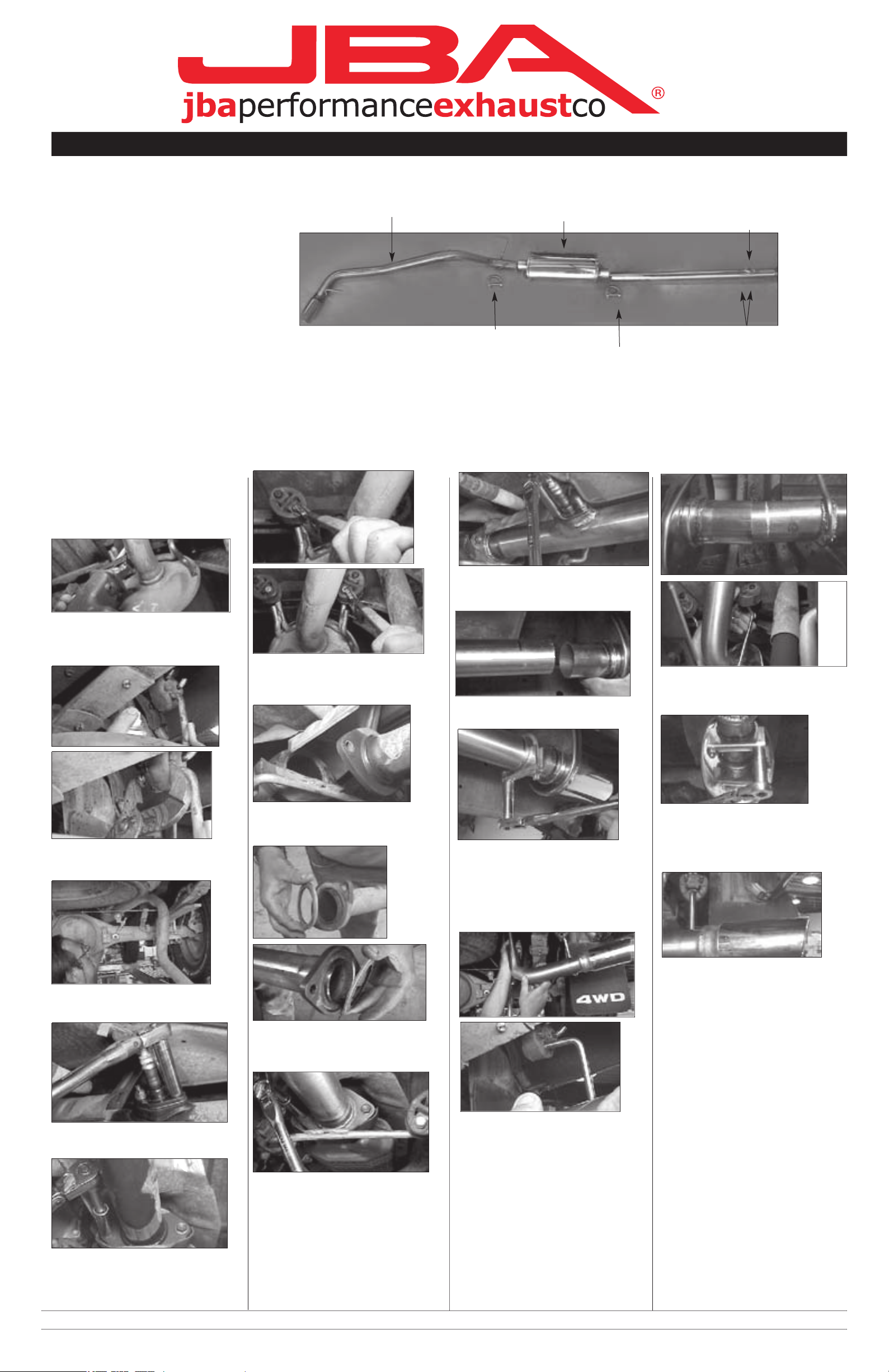
Part s List
A. Head pipe 1
B. Muffler, oval 1
C. Tail pipe with tip 1
D. 2-1/2" clamp 1
E. 2-1/2" clamp 1
F. 8mm nut 2
**Inst allation recommendation:
JBA recommends in most cases that the vehicle be taken to a reputable exhaust shop.
10.26.06
B
C
F
E
D
A
 Loading...