

Page 1
INSTALLATION INSTRUCTIONS
** Installation recommendation: JBA recommends in most case that the vehicle be taken to a reputable exhaust shop for installation.
40-3109
2004 Pontiac GTO 5.7L
40-3110
05-06 Pontiac GTO 6.0L
Recommended Tools:
15mm socket
9/16 deep socket
17mm socket
Pry bar
WD-40 or equivalent
Hi-temp silicone
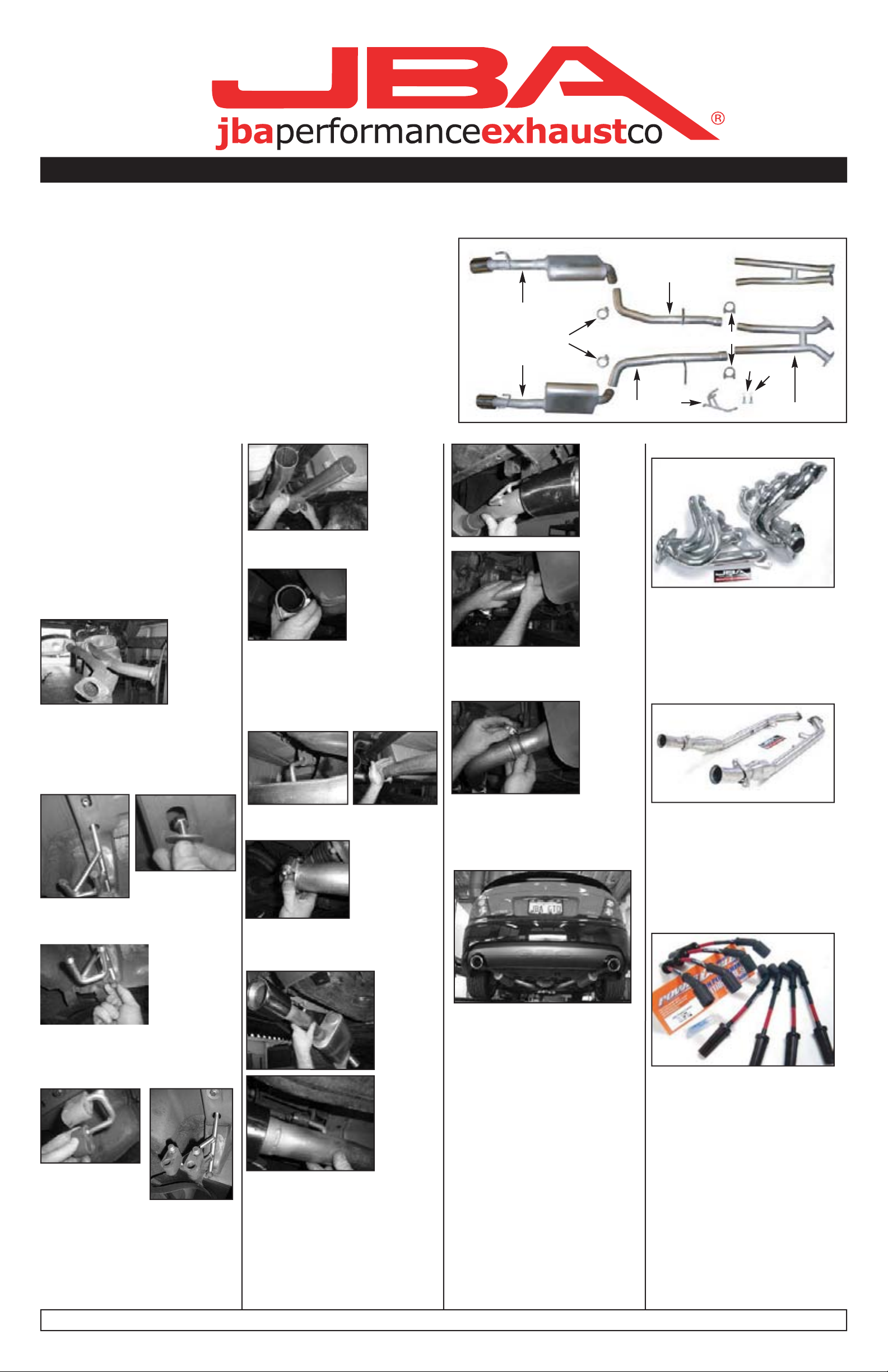
Parts List Qty.
A. H-pipe 1
B. Passenger side head pipe 1
C. Driver side head pipe 1
D. Passenger side muffler with tip 1
E. Driver side muffler with tip 1
F. Passenger side exhaust hanger 1
G. 2.5” Sure Seal™ clamp 2
H. 2.5” U-bolt clamp 2
I.
3/8 x 1 bolt w/ lock washer and fender washer
J.
10mm - 1.25 x 25 bolt w/ lock washer
1
1
C
E
G
D
B
F
for 40-3109 only
H
J
A
I
A
for
40-3110
for
40-3109
Start:
1. Remove and inventory new JBA
exhaust system.
2. Disconnect negative battery
cable and allow vehicle to cool.
3. With the vehicle raised and properly supported, unbolt the factory
exhaust system from that catalytic
converter assembly and pry the
hangers from the rubber isolators.
Remove the exhaust system.
4. Install the supplied exhaust
hanger (F) through the factory hole
on the passenger side of the car.
Use the supplied 3/8 x 1 bolt (I) with
fender washer and thread it into the
nut attached to the hanger.
8. Slip supplied 2.5” U-bolt clamps
(H) over end of H-pipe (A)
9. Insert hanger on passenger side
head-pipe (B) into factory rubber
isolator. Then slide end of headpipe onto end of H-pipe (A). Then
repeat on driver side with head pipe
(C) and tighten clamps (H).
13. Clip the Sure-Seal™ clamps (G)
over the muffler/head-pipe connection and tighten.
Other recommended products:
Get 20+hp and faster ET’s with a
set of smog legal stainless steel
JBA Cat4ward® headers.
Part No. Applicaton
1809S 04-06 Stainless
1809SJS 04-06 Silver ceramic
1809SJT 04-06 Titanium Ceramic
5. Use the supplied 10mm bolt with
lock washer (J) and attach other
end of the exhaust hanger (F).
6. Remove two rubber isolators
from the factory mid-pipe exhaust
hangers and install them on the
new exhaust hanger (F).
7. Install the new H-pipe (A) onto
the catalytic conve
blies using the factory gasket and
hardware. Apply a small bead of
Hi-temp silicone to ma
of the gasket exhaust flanges.
rter assem-
ting surface
10. Slip Sure-Seal™ clamps (G)
over end of head pipes (B) and (C).
11. Install muffler with tip assembly
(E) on to driver side rear isolators
and onto head-pipe (C).
12. Install
sembly (D) onto the passenger side
head-pipe (B).
the muffler with tip as-
14. Align the new tips of the system
for proper clearance from rear valance. Secure in place by tightening
clamps (G) and (H).
15. Using a soft cloth, remove all
prints from exhaust tip.
16. Check all clamps and connections for proper fit and alignment. Double check all clamps are
tightened and that all hangers are
secure in rubber grommets. It is
recommended that after installation
of the exhaust system you have all
slip conn
muffler shop.
NOTES:
1. All exhaust s
about 1” rearward when exhaust
temperature rises.
3. Use anti-seize on
clamps.
ections tack welded by a
ystems expand
threads of
Bolt-on serious power with JBA’s
new stainless steel high flow Midpipes. Available with or without cats
Part No. Application
2809SY 04 GTO no cats
2809SYC 04 GTO w/ cats
2810SY 05-06 GTO no cats
2810SYC 05-06 GTO w/ cats
Get more spark energy to your
plugs for increased power with JBA
Powercables™ ignition wires.
Part No. Application
0807 04-06 G
TO
JBA recommends
taking the vehicle to a muffler shop and having all slip connections tack welded. 4.23.07
 Loading...