

Page 1
INSTALLATION INSTRUCTIONS
INSTALLATION INSTRUCTIONS
INSTALLATION INSTRUCTIONS
INSTALLATION INSTRUCTIONS
**Installation recommendation:
**Installation recommendation:
**Installation recommendation:
**Installation recommendation:
JBA recommends in most cases that the vehicle be taken to a reputable exhaust shop.
JBA recommends in most cases that the vehicle be taken to a reputable exhaust shop.
JBA recommends in most cases that the vehicle be taken to a reputable exhaust shop.
JBA recommends in most cases that the vehicle be taken to a reputable exhaust shop.
G
G
G
40-3003
GM Pickup
GM Pickup
GM Pickup
GM Pickup
96-98 V8-5.7L Std. cab, Std. bed
96-98 V8-5.7L Std. cab, Std. bed
96-98 V8-5.7L Std. cab, Std. bed
96-98 V8-5.7L Std. cab, Std. bed
Part s List
Part s List
Part s List
T OOLS RECOMMENDED:
T OOLS RECOMMENDED:
T OOLS RECOMMENDED:
T OOLS RECOMMENDED:
reciprocating saw or hack saw
reciprocating saw or hack saw
reciprocating saw or hack saw
reciprocating saw or hack saw
prybar
prybar
prybar
prybar
rubber mallet
rubber mallet
rubber mallet
rubber mallet
ratchet
ratchet
ratchet
ratchet
15mm deep socket
15mm deep socket
15mm deep socket
15mm deep socket
9/16 box wrench or socket
9/16 box wrench or socket
9/16 box wrench or socket
9/16 box wrench or socket
7/8" open end wrench
7/8" open end wrench
7/8" open end wrench
7/8" open end wrench
pair of channel lock pliers
pair of channel lock pliers
pair of channel lock pliers
pair of channel lock pliers
13mm socket
13mm socket
13mm socket
13mm socket
anti-seize
anti-seize
anti-seize
anti-seize
impact wrench
impact wrench
impact wrench
impact wrench
spray lubricant or penetrating oil
spray lubricant or penetrating oil
spray lubricant or penetrating oil
spray lubricant or penetrating oil
TO ST ART :
TO ST ART :
TO ST ART :
TO ST ART :
1. Remove and inventory new JBA
1. Remove and inventory new JBA
1. Remove and inventory new JBA
1. Remove and inventory new JBA
exhaust.
exhaust.
exhaust.
exhaust.
2. Disconnect negative battery cable and
2. Disconnect negative battery cable and
2. Disconnect negative battery cable and
2. Disconnect negative battery cable and
allow vehicle exhaust to cool.
allow vehicle exhaust to cool.
allow vehicle exhaust to cool.
allow vehicle exhaust to cool.
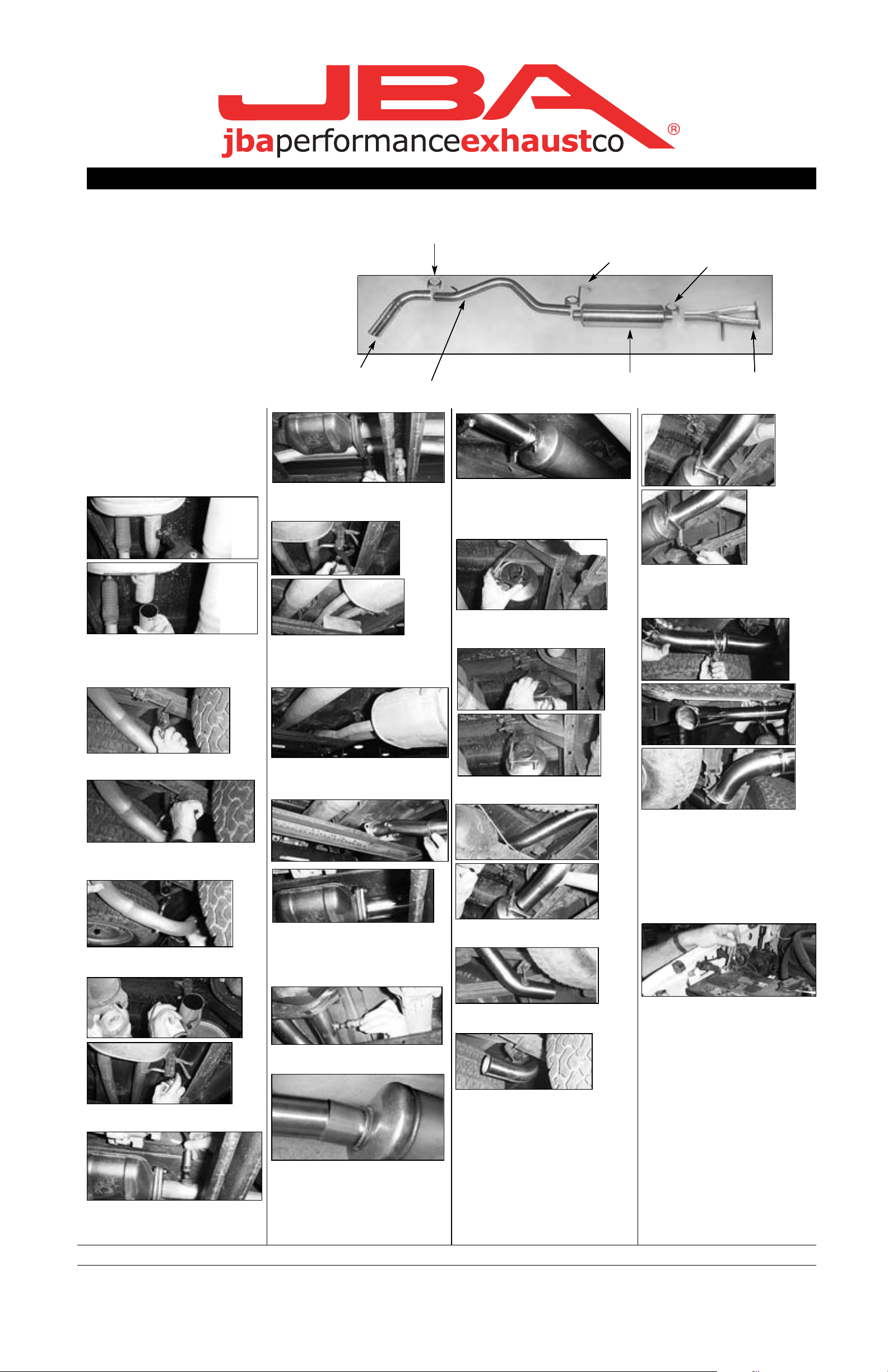
Part s List
A. Head pipe with hanger 1
A. Head pipe with hanger 1
A. Head pipe with hanger 1
A. Head pipe with hanger 1
B. Muffler 24" 1
B. Muffler 24" 1
B. Muffler 24" 1
B. Muffler 24" 1
C. Tail pipe with hanger 1
C. Tail pipe with hanger 1
C. Tail pipe with hanger 1
C. Tail pipe with hanger 1
D. Turn out 1
D. Turn out 1
D. Turn out 1
D. Turn out 1
E. Front muffler clamp 3" 1
E. Front muffler clamp 3" 1
E. Front muffler clamp 3" 1
E. Front muffler clamp 3" 1
F. Rear muffler clamp/hanger 3" 1
F. Rear muffler clamp/hanger 3" 1
F. Rear muffler clamp/hanger 3" 1
F. Rear muffler clamp/hanger 3" 1
G. Turn out clamp 3" 1
G. Turn out clamp 3" 1
G. Turn out clamp 3" 1
G. Turn out clamp 3" 1
9. Remove three nuts on three bolt flange
9. Remove three nuts on three bolt flange
9. Remove three nuts on three bolt flange
9. Remove three nuts on three bolt flange
using 15mm socket. You may want to use
using 15mm socket. You may want to use
using 15mm socket. You may want to use
using 15mm socket. You may want to use
some penetrating oil.
some penetrating oil.
some penetrating oil.
some penetrating oil.
D
D
D
D
G
C
C
C
C
15. With muffler (B) in place, install muf-
15. With muffler (B) in place, install muf-
15. With muffler (B) in place, install muf-
15. With muffler (B) in place, install muffler clamp (E) on slip fit joint. Position 1/4"
fler clamp (E) on slip fit joint. Position 1/4"
fler clamp (E) on slip fit joint. Position 1/4"
fler clamp (E) on slip fit joint. Position 1/4"
from lip. Tighten clamp completely with
from lip. Tighten clamp completely with
from lip. Tighten clamp completely with
from lip. Tighten clamp completely with
9/16" deep wall socket. NOTE: Use some
9/16" deep wall socket. NOTE: Use some
9/16" deep wall socket. NOTE: Use some
9/16" deep wall socket. NOTE: Use some
anti-seize on all threads.
anti-seize on all threads.
anti-seize on all threads.
anti-seize on all threads.
F
F
F
F
B
B
B
B
E
E
E
E
A
A
A
A
3. With vehicle raised and properly sup-
3. With vehicle raised and properly sup-
3. With vehicle raised and properly sup-
3. With vehicle raised and properly supported, using a reciprocating saw or hack
ported, using a reciprocating saw or hack
ported, using a reciprocating saw or hack
ported, using a reciprocating saw or hack
saw, cut the tail pipe approximately 3"
saw, cut the tail pipe approximately 3"
saw, cut the tail pipe approximately 3"
saw, cut the tail pipe approximately 3"
behind rear muffler hanger.
behind rear muffler hanger.
behind rear muffler hanger.
behind rear muffler hanger.
4. Spray lubricant on rear tail pipe hanger
4. Spray lubricant on rear tail pipe hanger
4. Spray lubricant on rear tail pipe hanger
4. Spray lubricant on rear tail pipe hanger
grommet.
grommet.
grommet.
grommet.
5. Using a pair of channel lock pliers,
5. Using a pair of channel lock pliers,
5. Using a pair of channel lock pliers,
5. Using a pair of channel lock pliers,
remove hanger rod from bottom hole of
remove hanger rod from bottom hole of
remove hanger rod from bottom hole of
remove hanger rod from bottom hole of
grommet.
grommet.
grommet.
grommet.
10. Using a pair of channel lock pliers,
10. Using a pair of channel lock pliers,
10. Using a pair of channel lock pliers,
10. Using a pair of channel lock pliers,
remove front and rear muffler hanger rods
remove front and rear muffler hanger rods
remove front and rear muffler hanger rods
remove front and rear muffler hanger rods
from bottom holes of grommets.
from bottom holes of grommets.
from bottom holes of grommets.
from bottom holes of grommets.
Note: support muffler before starting.
Note: support muffler before starting.
Note: support muffler before starting.
Note: support muffler before starting.
11. Remove muffler assembly pulling
11. Remove muffler assembly pulling
11. Remove muffler assembly pulling
11. Remove muffler assembly pulling
towards rear of vehicle. Note: use care not
towards rear of vehicle. Note: use care not
towards rear of vehicle. Note: use care not
towards rear of vehicle. Note: use care not
to damage gasket on three bolt flange.
to damage gasket on three bolt flange.
to damage gasket on three bolt flange.
to damage gasket on three bolt flange.
16. Install rear muffler clamp/hanger (F)
16. Install rear muffler clamp/hanger (F)
16. Install rear muffler clamp/hanger (F)
16. Install rear muffler clamp/hanger (F)
over slip joint on rear of muffler. Do not
over slip joint on rear of muffler. Do not
over slip joint on rear of muffler. Do not
over slip joint on rear of muffler. Do not
tighten at this time.
tighten at this time.
tighten at this time.
tighten at this time.
17. Slip clamp/hanger (F) into lower hole
17. Slip clamp/hanger (F) into lower hole
17. Slip clamp/hanger (F) into lower hole
17. Slip clamp/hanger (F) into lower hole
on rubber grommet.
on rubber grommet.
on rubber grommet.
on rubber grommet.
22. Position rear muffler clamp/hanger (F)
22. Position rear muffler clamp/hanger (F)
22. Position rear muffler clamp/hanger (F)
22. Position rear muffler clamp/hanger (F)
1/4" from lip on slip joint and tighten com-
1/4" from lip on slip joint and tighten com-
1/4" from lip on slip joint and tighten com-
1/4" from lip on slip joint and tighten completely with 9/16" deep wall socket. Note:
pletely with 9/16" deep wall socket. Note:
pletely with 9/16" deep wall socket. Note:
pletely with 9/16" deep wall socket. Note:
Use anti-seize on threads.
Use anti-seize on threads.
Use anti-seize on threads.
Use anti-seize on threads.
23. Slip turn out clamp (G) onto tail pipe.
23. Slip turn out clamp (G) onto tail pipe.
23. Slip turn out clamp (G) onto tail pipe.
23. Slip turn out clamp (G) onto tail pipe.
Slip turn out (D) on tail pipe (C) approx.
Slip turn out (D) on tail pipe (C) approx.
Slip turn out (D) on tail pipe (C) approx.
Slip turn out (D) on tail pipe (C) approx.
1-1/2î. Rotate tip to desired position leav-
1-1/2î. Rotate tip to desired position leav-
1-1/2î. Rotate tip to desired position leav-
1-1/2î. Rotate tip to desired position leaving clearance from body. Position clamp
ing clearance from body. Position clamp
ing clearance from body. Position clamp
ing clearance from body. Position clamp
(G) with threads in an upward position.
(G) with threads in an upward position.
(G) with threads in an upward position.
(G) with threads in an upward position.
Tighten completely with 9/16" deep wall
Tighten completely with 9/16" deep wall
Tighten completely with 9/16" deep wall
Tighten completely with 9/16" deep wall
socket. Note: use anti-seize on threads.
socket. Note: use anti-seize on threads.
socket. Note: use anti-seize on threads.
socket. Note: use anti-seize on threads.
6. Remove tail pipe assembly from the
6. Remove tail pipe assembly from the
6. Remove tail pipe assembly from the
6. Remove tail pipe assembly from the
rear of vehicle.
rear of vehicle.
rear of vehicle.
rear of vehicle.
7. Spray lubricant on front and rear muffler
7. Spray lubricant on front and rear muffler
7. Spray lubricant on front and rear muffler
7. Spray lubricant on front and rear muffler
hanger grommets.
hanger grommets.
hanger grommets.
hanger grommets.
8. Remove oxygen sensor with 7/8" open
8. Remove oxygen sensor with 7/8" open
8. Remove oxygen sensor with 7/8" open
8. Remove oxygen sensor with 7/8" open
end wrench.
end wrench.
end wrench.
end wrench.
12. Install head pipe (A) with three bolt
12. Install head pipe (A) with three bolt
12. Install head pipe (A) with three bolt
12. Install head pipe (A) with three bolt
flange. Install hanger through lower hole
flange. Install hanger through lower hole
flange. Install hanger through lower hole
flange. Install hanger through lower hole
in rubber grommet. Tighten three nuts
in rubber grommet. Tighten three nuts
in rubber grommet. Tighten three nuts
in rubber grommet. Tighten three nuts
using 15mm socket. Note: we recom-
using 15mm socket. Note: we recom-
using 15mm socket. Note: we recom-
using 15mm socket. Note: we recommend using anti-seize on threads.
mend using anti-seize on threads.
mend using anti-seize on threads.
mend using anti-seize on threads.
13. Install oxygen sensor using 7/8"
13. Install oxygen sensor using 7/8"
13. Install oxygen sensor using 7/8"
13. Install oxygen sensor using 7/8"
wrench.
wrench.
wrench.
wrench.
14. Slip muffler (B) on head pipe approxi-
14. Slip muffler (B) on head pipe approxi-
14. Slip muffler (B) on head pipe approxi-
14. Slip muffler (B) on head pipe approximately 2". Note: You may have to tap it in
mately 2". Note: You may have to tap it in
mately 2". Note: You may have to tap it in
mately 2". Note: You may have to tap it in
with a rubber mallet. Make sure JBA logo
with a rubber mallet. Make sure JBA logo
with a rubber mallet. Make sure JBA logo
with a rubber mallet. Make sure JBA logo
is to the rear.
is to the rear.
is to the rear.
is to the rear.
18. Install tail pipe (C) from rear into slip
18. Install tail pipe (C) from rear into slip
18. Install tail pipe (C) from rear into slip
18. Install tail pipe (C) from rear into slip
joint on muffler (B). Slip approx. 2".
joint on muffler (B). Slip approx. 2".
joint on muffler (B). Slip approx. 2".
joint on muffler (B). Slip approx. 2".
19. Slip rear tail pipe (C) hanger into
19. Slip rear tail pipe (C) hanger into
19. Slip rear tail pipe (C) hanger into
19. Slip rear tail pipe (C) hanger into
lower hole in rubber grommet.
lower hole in rubber grommet.
lower hole in rubber grommet.
lower hole in rubber grommet.
20. Position tail pipe (C) so hanger is not
20. Position tail pipe (C) so hanger is not
20. Position tail pipe (C) so hanger is not
20. Position tail pipe (C) so hanger is not
cocked at an angle, and rubber grommet
cocked at an angle, and rubber grommet
cocked at an angle, and rubber grommet
cocked at an angle, and rubber grommet
is angled forward.
is angled forward.
is angled forward.
is angled forward.
21. Inspect clearance around rear-end
21. Inspect clearance around rear-end
21. Inspect clearance around rear-end
21. Inspect clearance around rear-end
shock and spare tire.
shock and spare tire.
shock and spare tire.
shock and spare tire.
24. Using a soft cloth, remove all prints
24. Using a soft cloth, remove all prints
24. Using a soft cloth, remove all prints
24. Using a soft cloth, remove all prints
from turnout tip.
from turnout tip.
from turnout tip.
from turnout tip.
25. Lower vehicle and reattach the nega-
25. Lower vehicle and reattach the nega-
25. Lower vehicle and reattach the nega-
25. Lower vehicle and reattach the negative battery cable.
tive battery cable.
tive battery cable.
tive battery cable.
NOTES:
NOTES:
NOTES:
NOTES:
1) It may be necessary to loosen and
1) It may be necessary to loosen and
1) It may be necessary to loosen and
1) It may be necessary to loosen and
realign the spare tire for proper clear-
realign the spare tire for proper clear-
realign the spare tire for proper clear-
realign the spare tire for proper clearance.
ance.
ance.
ance.
2) All exhaust systems will expand about
2) All exhaust systems will expand about
2) All exhaust systems will expand about
2) All exhaust systems will expand about
1î rearward when exhaust temperature
1î rearward when exhaust temperature
1î rearward when exhaust temperature
1î rearward when exhaust temperature
start to rise.
start to rise.
start to rise.
start to rise.
3) Use Anti-seize on threads of clamps D,
3) Use Anti-seize on threads of clamps D,
3) Use Anti-seize on threads of clamps D,
3) Use Anti-seize on threads of clamps D,
E and F.
E and F.
E and F.
E and F.
We recommend taking the truck to a muffler shop and having all slip connections tack welded.
We recommend taking the truck to a muffler shop and having all slip connections tack welded.
We recommend taking the truck to a muffler shop and having all slip connections tack welded.
We recommend taking the truck to a muffler shop and having all slip connections tack welded.
17092
17092
17092
17092
4/17/07
 Loading...