

Page 1
INSTALLATION INSTRUCTIONS
40-2518
1996-1/2 - 97 Ford F-150
Ext.Cab/Std. Bed 2-4WD
V8-4.6L, 5.4L
TOOLS RECOMMENDED:
TO ST ART :
9/16 deep socket
15mm deep socket
ratchet
6" extension
rubber mallet
pair of channel lock pliers, 10"
spray lubricant or penetrating oil
anti-seize
2. Disconnect negative battery cable and
allow vehicle exhaust to cool.
3. With vehicle raised and properly
supported, remove front exhaust clamp
using a 15mm socket.
4. Spray lubricant on hanger rods in
lower holes of rubber grommets at the
tail pipe and end of muffler.
5. With muffler properly supported,
using a pair of channel lock pliers,
remove rear tail pipe and rear muffler
hangers from lower holes in rubber
grommets.
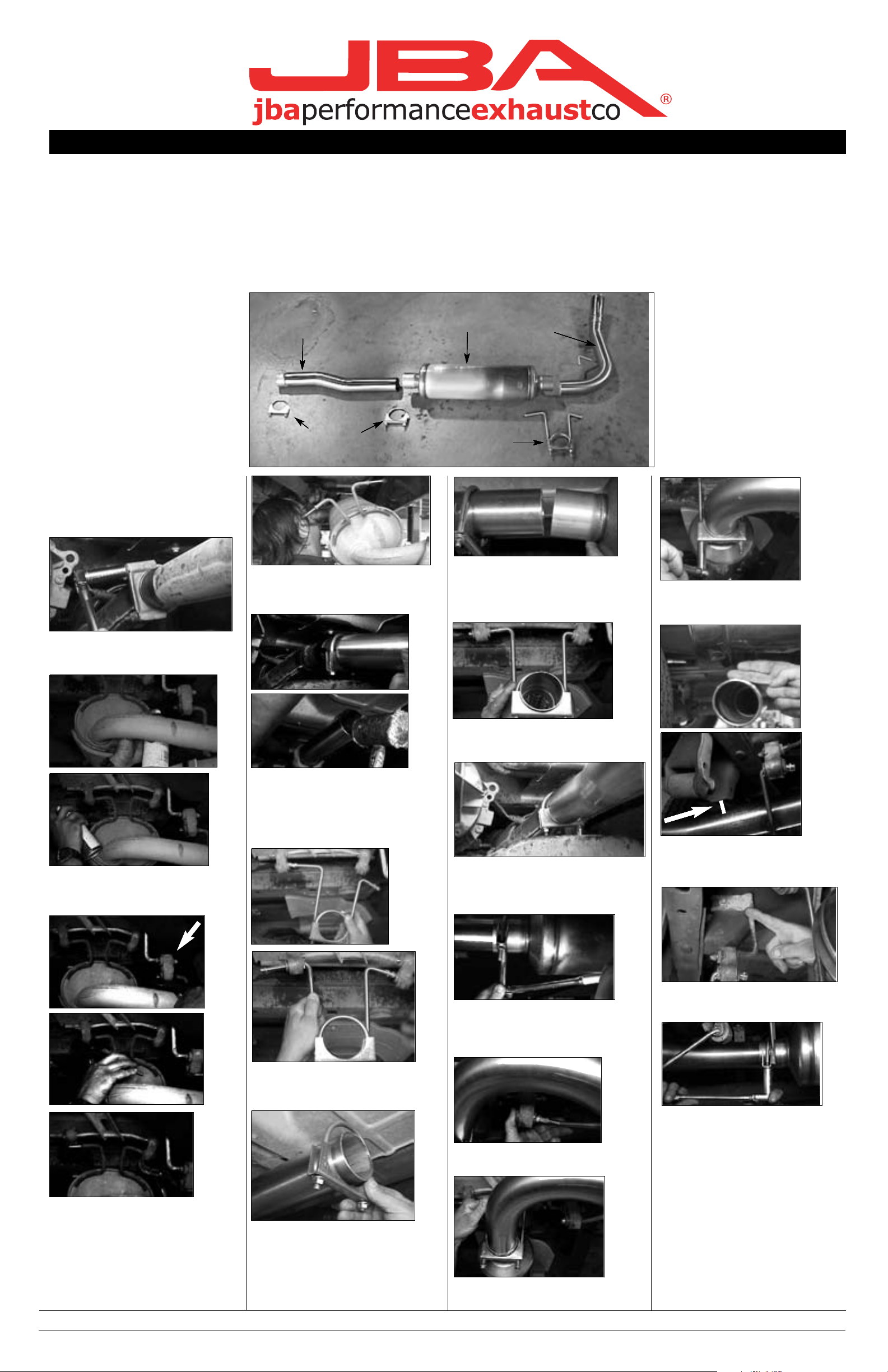
1. Remove and inventory new JBA
exhaust.
6. Using some form of heat and force,
disengage and remove muffler assembly
without damaging converter pipe.
7. Slip 2-1/2" clamp (D) over end of head
pipe (A). Install head pipe aligning notch
with locating pin. Make sure pin is bottomed out in notch.
NOTE: you may have to tap it with a rubber mallet.
12. Position 2-1/2" clamp (D) over front
slip joint on head pipe (A) and tighten
completely using a 9/16" deep socket.
NOTE: use anti seize on threads.
13. Position 3" clamp (E) over slip joint on
front of muffler (B) and tighten completely
using a 9/16" deep socket.
NOTE: use anti seize on threads.
16. Using a 9/16" deep socket, snug nuts
up on 3" clamp/hanger (F).
NOTE: use anti seize on all threads.
18. Tighten 3" clamp/hanger (F) completely using a 9/16" deep socket.
19. After installation, it is recommended
that all clamps be retightened.
20. Tack weld all slip connections in
three spot s.
21. Using a soft cloth, remove all prints
from turnout tip (D).
22. Lower vehicle and reattach the negative battery cable.
NOTE:
1) Use Anti-seize on threads of clamps.
11. Position 3" clamp/hanger (F) over
end of muffler (B) and hand tighten at
this time.
8. Install 3" clamp/hanger (F) into the
rear muffler grommets. NOTE: Longest
ìLî rod points towards drivers side.
5. With muffler properly supported,
using a pair of channel lock pliers,
remove rear tail pipe and rear muffler
hangers from lower holes in rubber
grommets.
1. Remove and inventory new JBA
exhaust.
6. Using some form of heat and force,
disengage and remove muffler assembly
without damaging converter pipe.
7. Slip 2-1/2" clamp (D) over end of head
pipe (A). Install head pipe aligning notch
with locating pin. Make sure pin is bottomed out in notch.
NOTE: you may have to tap it with a rubber mallet.
12. Position 2-1/2" clamp (D) over front
slip joint on head pipe (A) and tighten
NOTE: use anti seize on threads.
13. Position 3" clamp (E) over slip joint on
front of muffler (B) and tighten completely
using a 9/16" deep socket.
NOTE: use anti seize on threads.
16. Using a 9/16" deep socket, snug nuts
NOTE: use anti seize on all threads.
18. Tighten 3" clamp/hanger (F) completely using a 9/16" deep socket.
19. After installation, it is recommended
that all clamps be retightened.
20. Tack weld all slip connections in
three spot s.
21. Using a soft cloth, remove all prints
from turnout tip (D).
22. Lower vehicle and reattach the negative battery cable.
NOTE:
1) Use Anti-seize on threads of clamps.
11. Position 3" clamp/hanger (F) over
end of muffler (B) and hand tighten at
this time.
8. Install 3" clamp/hanger (F) into the
rear muffler grommets. NOTE: Longest
ìLî rod points towards drivers side.
NOTE: you may have to adjust stock
hanger next to rail frame.
17) Rotate tail pipe (C) to desired
location, making sure there is clearance on body panel and spring perch.
NOTE: you may have to adjust stock
hanger next to rail frame.
17) Rotate tail pipe (C) to desired
location, making sure there is clearance on body panel and spring perch.
NOTE: you may have to adjust stock
hanger next to rail frame.
17) Rotate tail pipe (C) to desired
location, making sure there is clearance on body panel and spring perch.
NOTE: you may have to adjust stock
hanger next to rail frame.
17) Rotate tail pipe (C) to desired
location, making sure there is clearance on body panel and spring perch.
14. Install tail pipe (C) hanger rod into
rubber grommet.
14. Install tail pipe (C) hanger rod into
rubber grommet.
14. Install tail pipe (C) hanger rod into
rubber grommet.
14. Install tail pipe (C) hanger rod into
rubber grommet.
15. Slip tail pipe (C) into rear muffler slip
joint, making sure it bottoms out.
15. Slip tail pipe (C) into rear muffler slip
joint, making sure it bottoms out.
15. Slip tail pipe (C) into rear muffler slip
joint, making sure it bottoms out.
15. Slip tail pipe (C) into rear muffler slip
joint, making sure it bottoms out.
9. Install 3" clamp (E) over end of
head pipe.
9. Install 3" clamp (E) over end of
head pipe.
9. Install 3" clamp (E) over end of
head pipe.
9. Install 3" clamp (E) over end of
head pipe.
10. With the JBA logo to the rear of
the vehicle, slip muffler (B) over end
of head pipe (A) making sure slip is
bottomed out. NOTE: Y
to tap it with a rubber mallet.
10. With the JBA logo to the rear of
the vehicle, slip muffler (B) over end
of head pipe (A) making sure slip is
bottomed out. NOTE:
to tap it with a rubber mallet.
10. With the JBA logo to the rear of
the vehicle, slip muffler (B) over end
of head pipe (A) making sure slip is
bottomed out. NOTE:
to tap it with a rubber mallet.
10. With the JBA logo to the rear of
the vehicle, slip muffler (B) over end
of head pipe (A) making sure slip is
bottomed out. NOTE: ou may have
to tap it with a rubber mallet.
Part s List
A. Head pipe 1
B. Muffler,round 1
C. Tail pipe/Turn out 1
D. 2-1/2" clamp 1
E. 3" clamp 1
F. 3" clamp/hanger 1
**Installation recommendation:
JBA recommends in most cases that the vehicle be taken to a reputable exhaust shop.
6-21-02
Part s List
A. Head pipe 1
B. Muffler,round 1
C. Tail pipe/Turn out 1
D. 2-1/2" clamp 1
E. 3" clamp 1
F. 3" clamp/hanger 1
**Installation recommendation:
JBA recommends in most cases that the vehicle be taken to a reputable exhaust shop.
6-21-02
Part s List
A. Head pipe 1
B. Muffler,round 1
C. Tail pipe/Turn out 1
D. 2-1/2" clamp 1
E. 3" clamp 1
F. 3" clamp/hanger 1
**Installation recommendation:
JBA recommends in most cases that the vehicle be taken to a reputable exhaust shop.
6-21-02
Part s List
A. Head pipe 1
B. Muffler,round 1
C. Tail pipe/Turn out 1
D. 2-1/2" clamp 1
E. 3" clamp 1
F. 3" clamp/hanger 1
**Installation recommendation:
JBA recommends in most cases that the vehicle be taken to a reputable exhaust shop.
6-21-02
B
C
D
E
F
A
B
C
D
E
F
A
B
C
D
E
F
A
B
C
D
E
F
A
W e recommend t aking the truck to a muffler shop and having all slip connections t ack welded.
 Loading...