

Page 1
INSTALLATION INSTRUCTIONS
1988-94 Ford F-250, F-350
V8-5.8L, 7.5L Ext. cab/Long bed
TOOLS RECOMMENDED:
TO ST ART :
ratchet
9/16 deep socket
15mm deep socket
9/16" box wrench
reciprocating saw or hack saw
pair of channel lock pliers, 12"
spray lubricant or penetrating oil
anti-seize
2. Disconnect negative battery cable and
allow vehicle exhaust to cool.
3. With vehicle raised and properly supported, using a reciprocating saw or hack
saw, cut tail pipes approximately 3"
behind rear of muffler.
4. Spray lubricant on rear tail pipe hanger
rubber grommet.
5. Using a pair of channel lock pliers,
remove tail pipe hanger rod from rubber
grommet.
10. Using some form of heat and force,
disengage and remove muffler assembly
without damaging converter pipe.
15. Install 3" clamp/hanger (G) into rear
muffler rubber grommets with flat bar
towards driver side. Slip clamp/hanger (G)
over end of slip joint of muffler (B). Hand
tighten clamp at this time.
NOTE: Use anti-seize on threads.
1. Remove and inventory new JBA
exhaust.
11. Install head pipe (A) aligning notch
with locating pin. NOTE: Make sure pin is
bottomed out in notch.
6. Remove tail pipe assembly from rear of
vehicle.
7. Spray penetrating lubricant on front
head pipe clamp threads at rear of converter and remove using a 15mm deep
socket..
12. Install 2-1/2" clamp (E) on front portion of head pipe (A). Tighten completely
with 9/16" deep socket. NOTE: Use antiseize on threads.
17. Install 3" clamp/hanger with heat
shield (H) into rear tail pipe rubber grommet. Slip clamp over end of tail pipe (C).
18. Install turn out (D) over end of tail pipe
(C) and tighten clamp/hanger (H) lightly with
9/16" wrench. NOTE: Put anti-seize on
threads.
22. After installation, it is recommended that
all clamps be retightened and joints tack
welded in 3 spots.
21. Rotate turn out (D) to desired position
and tighten 3î clamp/hanger (H) completely.
23. Using a soft cloth, remove all prints from
turn out tip.
24. Lower vehicle and reattach the negative
battery cable.
NOTES:
1) It may be necessary to loosen and realign
the spare tire for proper clearance.
2) All exhaust systems will expand about 1"
rearward when exhaust temperature start to
rise.
3) Use Anti-seize on threads of clamps.
13. Install 3" clamp/hanger (F) into front
muffler hanger rubber grommet and position
clamp over end of end of head pipe (A).
14. Install muffler (B) over head pipe (A)
with JBA logo towards rear of vehicle
making sure muffler bottoms out on slip
joint.
8. Spray lubricant on front and rear muffler
hanger rod grommets.
9. With muffler supported, using channel
lock pliers, remove front and rear muffler
hanger rods from rubber grommets.
16. Install tail pipe (C) into muffler (B)
from rear of vehicle. Longest end towards
muffler making sure tail pipe bottoms out
in slip joint.
16. Install tail pipe (C) into muffler (B)
from rear of vehicle. Longest end towards
muffler making sure tail pipe bottoms out
in slip joint.
16. Install tail pipe (C) into muffler (B)
from rear of vehicle. Longest end towards
muffler making sure tail pipe bottoms out
in slip joint.
16. Install tail pipe (C) into muffler (B)
from rear of vehicle. Longest end towards
muffler making sure tail pipe bottoms out
in slip joint.
19. Position 3" clamp/hanger (F), level and
tighten completely using 9/16" seep socket.
NOTE: Use anti-seize on threads.
19. Position 3" clamp/hanger (F), level and
tighten completely using 9/16" seep socket.
NOTE: Use anti-seize on threads.
19. Position 3" clamp/hanger (F), level and
tighten completely using 9/16" seep socket.
NOTE: Use anti-seize on threads.
19. Position 3" clamp/hanger (F), level and
tighten completely using 9/16" seep socket.
NOTE: Use anti-seize on threads.
20. Position tail pipe (C) to desired position
and tighten 3" clamp/hanger (G) completely
using 9/16" deep socket.
20. Position tail pipe (C) to desired position
and tighten 3" clamp/hanger (G) completely
using 9/16" deep socket.
20. Position tail pipe (C) to desired position
and tighten 3" clamp/hanger (G) completely
using 9/16" deep socket.
20. Position tail pipe (C) to desired position
and tighten 3" clamp/hanger (G) completely
using 9/16" deep socket.
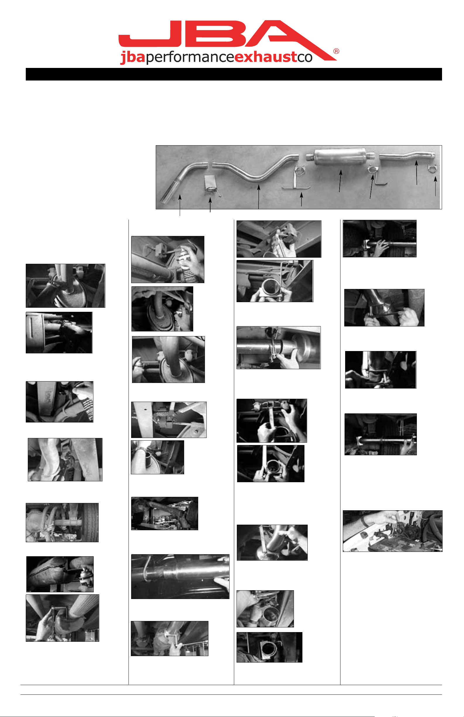
W e recommend taking the truck to a muffler shop and having all slip connections tack welded.
A. Head pipe 1
B. Muffler, 24" 1
C. Tail pipe 1
D. Turn out 1
E. 2-1/2" H.P. clamp 1
F. Front muffler 3" clamp/hanger 1
G. Rear muffler 3" clamp/hanger 1
H. Turn out 3" clamp/hanger w/shield 1
**Installation recommendation:
JBA recommends in most cases that the vehicle be taken to a reputable exhaust shop.
17041
6-20-02
H
D
B
G
F
A
E
C
Part s List
H
D
B
G
F
A
E
C
Part s List
H
D
B
G
F
A
E
C
Part s List
H
D
B
G
F
A
E
C
Part s List
40-2509
 Loading...