

Page 1
INSTALLATION INSTRUCTIONS
1997-00 Ford Expedition
V8-4.6, 5.4L, 2&4 W/D
TOOLS RECOMMENDED:
TO START :
ratchet
9/16 deep socket
15mm box wrench
15mm socket
pair of 10î channel lock pliers
reciprocating saw or hack saw
prybar
spray lubricant or penetrating oil
rubber mallet
anti-seize
2. Disconnect negative battery cable
and allow vehicle exhaust to cool.
3. With vehicle raised and properly
supported, using a reciprocating saw
or hack saw, cut tail pipe off approximately 2" behind rear muffler.
4. Spray lubricant on front and rear tail
pipe rubber grommetslower hole.
5. Using a pair of channel lock pliers,
remove hanger rod from lower hole of
rear tail pipe rubber grommet.
9. With muffler properly supported, using
a pair of channel lock pliers, remove the
two rear muffler hangers from lower
holes in rubber grommets.
16. Slip 3" clamp/hanger (G) over
end of muffler (B). Hand tighten only
at this time.
1. Remove and inventory new
JBA exhaust.
10. Using some form of force or heat on
muffler slip joint, disengage and remove
muffler assembly.
NOTE: do not damage stock head pipe.
6. Remove tail pipe from rear of vehicle.
19. Install the rear tail pipe hanger
into the lower hole in rubber grommet. Position tail pipe so that rear
hanger is not at an angle.
20. Tighten rear muffler 3"
clamp/hanger (G) completely using
9/16" deep socket. NOTE: use
anti-seize on threads.
24. After installation, it is recommended
that all clamps be retightened and joints
tach welded in 3 spots.
25. Using a soft cloth, remove all prints
from turnout tip.
26. Lower vehicle and reattach the negative battery cable.
NOTES:
1) All exhaust systems will expand about
1î rearward when exhaust temperature
start to rise.
2) Use Anti-seize on threads of clamps.
13. Install 3" clamp (F) over end of head
pipe (A). Do not tighten at this time.
14. Install rear muffler 3"
clamp/hanger (G) into lower holes
of rubber grommets.
NOTE: WELDS ON HANGER
RODS FACE FORWARD.
15. Install muffler (B) over head pipe (A)
with JBA logo towards rear of vehicle
making sure slip joint is bottomed out
completely.
7. Using some type of prybar, bend
tab up on front muffler clamp.
8. Using a 15mm box wrench or 15 mm
socket, remove front muffler clamp.
5. Using a pair of channel lock pliers,
remove hanger rod from lower hole of
rear tail pipe rubber grommet.
9. With muffler properly supported, using
a pair of channel lock pliers, remove the
two rear muffler hangers from lower
holes in rubber grommets.
16. Slip 3" clamp/hanger (G) over
end of muffler (B). Hand tighten only
at this time.
1. Remove and inventory new
JBA exhaust.
10. Using some form of force or heat on
muffler slip joint, disengage and remove
muffler assembly.
NOTE: do not damage stock head pipe.
6. Remove tail pipe from rear of vehicle.
19. Install the rear tail pipe hanger
into the lower hole in rubber grommet. Position tail pipe so that rear
hanger is not at an angle.
20. Tighten rear muffler 3"
clamp/hanger (G) completely using
9/16" deep socket. NOTE: use
anti-seize on threads.
24. After installation, it is recommended
that all clamps be retightened and joints
tach welded in 3 spots.
25. Using a soft cloth, remove all prints
from turnout tip.
26. Lower vehicle and reattach the negative battery cable.
NOTES:
1) All exhaust systems will expand about
1î rearward when exhaust temperature
start to rise.
2) Use Anti-seize on threads of clamps.
13. Inst
pipe (A). Do not tighten at this time.
14. Install rear muffler 3"
clamp/hanger (G) into lower holes
of rubber grommets.
NOTE: WELDS ON HANGER
RODS FACE FORWARD.
15. Install muffler (B) over head pipe (A)
with JBA logo towards rear of vehicle
making sure slip joint is bottomed out
completely.
7. Using some type of prybar, bend
tab up on front muffler clamp.
8. Using a 15mm box wrench or 15 mm
socket, remove front muffler clamp.
11b. Install JBA head pipe (A), aligning notch with locating pin.
NOTE: make sure notch is bottomed
out on pin.
11b. Install JBA head pipe (A), aligning notch with locating pin.
NOTE: make sure notch is bottomed
out on pin.
11b. Install JBA head pipe (A), aligning notch with locating pin.
NOTE: make sure notch is bottomed
out on pin.
11b. Install JBA head pipe (A), aligning notch with locating pin.
NOTE: make sure notch is bottomed
out on pin.
12. Install 2-1/2" clamp (E) over slip
joint on head pipe (A) and tighten
completely using a 9/16" deep wall
socket.
NOTE: make sure clamp is positioned just behind locating pin.
12. Install 2-1/2" clamp (E) over slip
joint on head pipe (A) and tighten
completely using a 9/16" deep wall
socket.
NOTE: make sure clamp is positioned just behind locating pin.
12. Install 2-1/2" clamp (E) over slip
joint on head pipe (A) and tighten
completely using a 9/16" deep wall
socket.
NOTE: make sure clamp is positioned just behind locating pin.
12. Install 2-1/2" clamp (E) over slip
joint on head pipe (A) and tighten
completely using a 9/16" deep wall
socket.
NOTE: make sure clamp is positioned just behind locating pin.
17. Position front muffler clamp (F) over
slip joint and tighten completely using
9/16" deep socket.
NOTE: use anti-seize on all threads.
17. Position front muffler clamp (F) over
slip joint and tighten completely using
9/16" deep socket.
NOTE: use anti-seize on all threads.
17. Position front muffler clamp (F) over
slip joint and tighten completely using
9/16" deep socket.
NOTE: use anti-seize on all threads.
17. Position front muffler clamp (F) over
slip joint and tighten completely using
9/16" deep socket.
NOTE: use anti-seize on all threads.
18. Install tail pipe (C) from rear of
vehicle and slip into muffler (B).
NOTE: make sure that the end of
the tail pipe with the hanger is at the
the rear of the vehicle.
18. Install tail pipe (C) from rear of
vehicle and slip into muffler (B).
NOTE: make sure that the end of
the tail pipe with the hanger is at the
the rear of the vehicle.
18. Install tail pipe (C) from rear of
vehicle and slip into muffler (B).
NOTE: make sure that the end of
the tail pipe with the hanger is at the
the rear of the vehicle.
18. Install tail pipe (C) from rear of
vehicle and slip into muffler (B).
NOTE: make sure that the end of
the tail pipe with the hanger is at the
the rear of the vehicle.
21. Install 3" clamp (H) over end of tail
pipe. Do not tighten at this time.
21. Install 3" clamp (H) over end of tail
pipe. Do not tighten at this time.
21. Install 3" clamp (H) over end of tail
pipe. Do not tighten at this time.
21. Install 3" clamp (H) over end of tail
pipe. Do not tighten at this time.
22. Install turn out (D) over end of tail
pipe (C). Do not tighten at this time.
22. Install turn out (D) over end of tail
pipe (C). Do not tighten at this time.
22. Install turn out (D) over end of tail
pipe (C). Do not tighten at this time.
22. Install turn out (D) over end of tail
pipe (C). Do not tighten at this time.
23. Rotate turn out (D) to desired position
leaving clearance from body. Position 3"
clamp (H) over slip joint and tighten completely using 9/16" deep socket.
NOTE: use anti-seize on all threads
23. Rotate turn out (D) to desired position
leaving clearance from body. Position 3"
clamp (H) over slip joint and tighten completely using 9/16" deep socket.
NOTE: use anti-seize on all threads
23. Rotate turn out (D) to desired position
leaving clearance from body. Position 3"
clamp (H) over slip joint and tighten completely using 9/16" deep socket.
NOTE: use anti-seize on all threads
23. Rotate turn out (D) to desired position
leaving clearance from body. Position 3"
clamp (H) over slip joint and tighten completely using 9/16" deep socket.
NOTE: use anti-seize on all threads
We recommend taking the truck to a muffler shop and having all slip connections tack welded.
A. Head pipe 1
B. Muffler 24" oval 1
C. Tail pipe 1
D. Turn out 1
E. Head pipe 2-1/2" clamp 1
F. Front muffler 3" clamp 1
G. Rear muffler 3" clamp/hanger 1
H. Turn out 3" clamp 1
**Installation recommendation:
JBA recommends in most cases that the vehicle be taken to reputable exhaust shop.
17003
We recommend taking the truck to a muffler shop and having all slip connections tack welded.
A. Head pipe 1
B. Muffler 24" oval 1
C. Tail pipe 1
D. Turn out with hanger 1
E. Head pipe 2-1/2" clamp 1
F. Front muffler 3" clamp 1
G. Rear muffler 3" clamp/hanger 1
H. Turn out 3" clamp 1
**Installation recommendation:
JBA recommends in most cases that the vehicle be taken to reputable exhaust shop.
17003
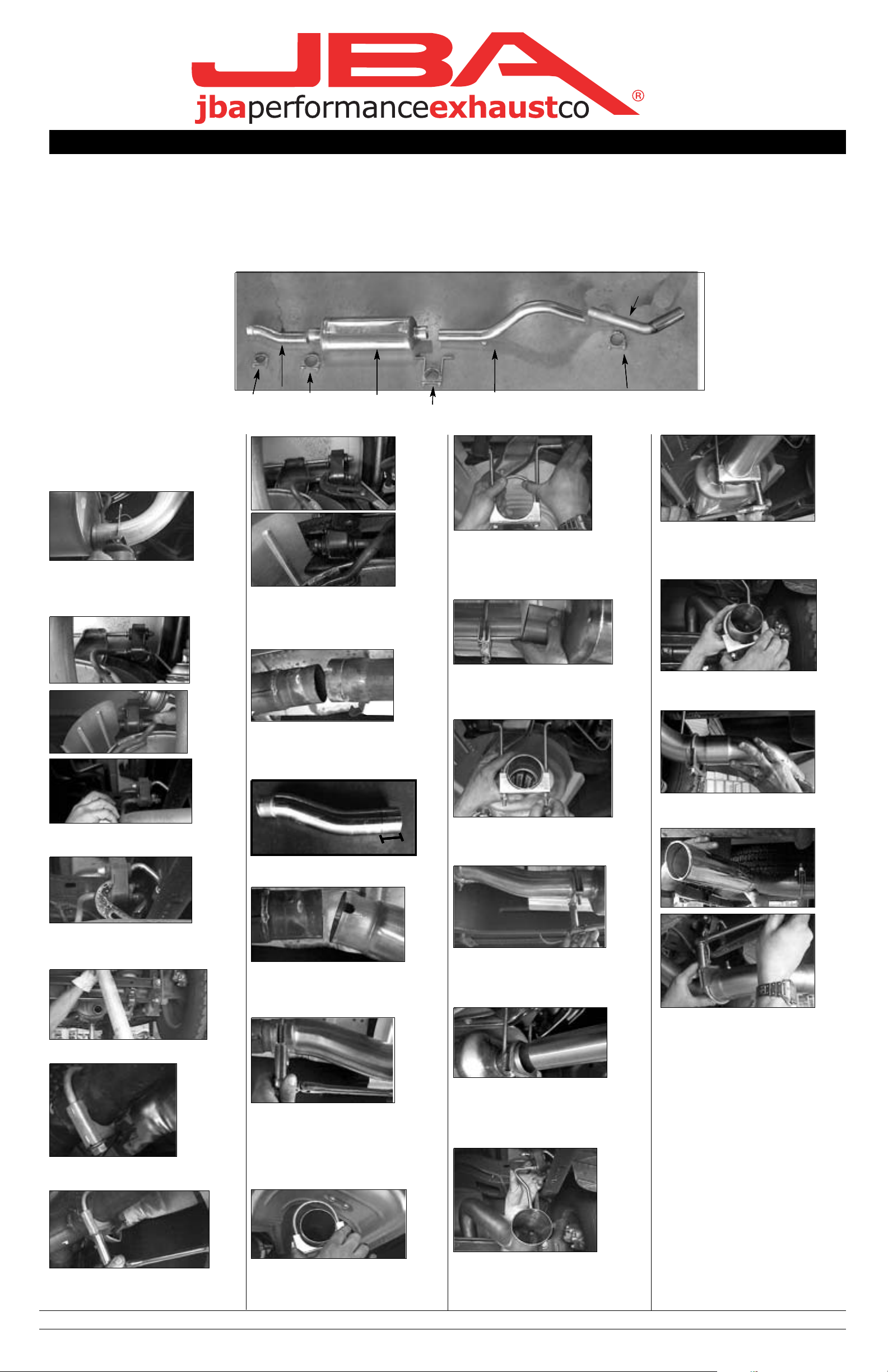
F
H
G
E
A
C
B
F
H
G
E
A
C
B
F
H
G
E
A
C
B
F
H
G
E
A
C
D
B
Part s List
11a. On 1997 4 w/d models, head pipe
(A) will need 2" cut off from muffler end.
2"
Part s List
11a. On 1997 4 w/d models, head pipe
(A) will need 2" cut off from muffler end.
2"
Part s List
11a. On 1997 4 w/d models, head pipe
(A) will need 2" cut off from muffler end.
2"
Part s List
11a. On 1997 4 w/d models, head pipe
(A) will need 2" cut off from muffler end.
2"
40-2502
 Loading...