

Page 1
INSTALLATION INSTRUCTIONS
** Installation recommendation: JBA recommends in most case that the vehicle be taken to a reputable exhaust shop for installation.
40-1532
00-03 Dodge Dakota 3.9/4.7L, Quad Cab / Short Bed
Recommended Tools:
15mm deep socket
10mm wrench
1/2” wrench
1/2” socket
9/16” deep socket
ratchet
Pair of channel lock pliers
Reciprocating saw or hack saw
rubber mallet
prybar
anti-seize
spray lubricant or penetrating oil
TO START:
1. Remove and inventory new JBA
exhaust
2. Disconnect negative battery cable
and allow vehicle exhaust to cool.
3. With vehicle raised and properly
supported, using a reciprocating saw
or hack saw cut tail pipe off at rear of
mufer in front of hanger rod.
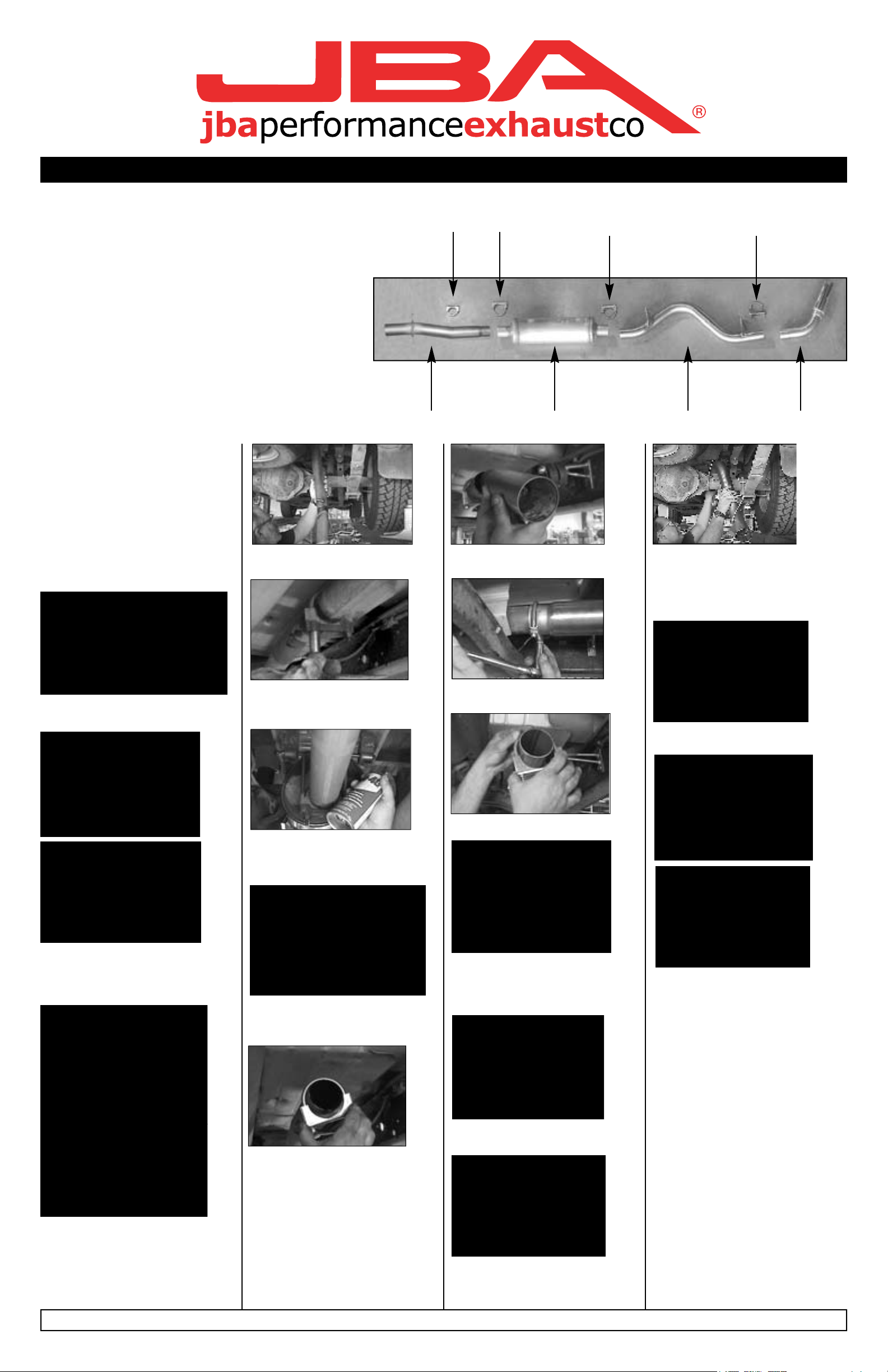
Parts List:
A. Head pipe 1
B. Mufer 1
C. Tail Pipe 1
D. Turn out 1
E. 2-1/2” Clamp 1
F. 3” Clamp 3
6. Remove the tail pipe assembly from
the rear of vehicle.
E F
F F
A B C D
11. Install head pipe (A) Make sure
notch bottoms out on locating pin.
17. Install tail pipe (C) over axle from
rear of vehicle with short end of tube
towards the mufer (B). Slip tail pipe
(C) onto mufer (B) and make sure to
bottom out connection.
4. Spray lubricant on front and rear tail
pipe hanger rubber grommets.
5. Using a pair of channel lock pliers,
remove the hanger rods from the bottom hole of the front and rear hanger
grommets.
7. Spray on front head pipe clamp
threads and remove using a 15mm
deep socket.
8. With mufer properly supported, using a pair of channel lock pliers remove
front mufer hanger rods from lower
hole in rubber grommets.
9. Using some form of heat and force,
remove the mufer assembly with out
damaging converter pipe.
12. Tighten 2-1/2” clamp (E) over con-
nection using 9/16 deep socket.
13. Slip 3” clamp (F) over end of head
pipe (A).
14. Install JBA mufer (B) over end of
head pipe (A) with logo facing rear-
ward. Make sure to bottom out slip
connection.
18. Install front and rear tail pipe
hanger rods
19. Align tail pipe (C) and tighten 3”
clamp (F) over slip joint completely.
20. Install 3” clamp (F) over end of tail
pipe (C) then slip turn out (D) over end
of tail pipe.
21. Position turn out (D) to desired
position then 3” clamp over slip joint
and tighten completely with 9/16 deep
socket.
15. Place 3” clamp (F) over slip joint
and tighten completely.
10. Install the 2-1/2” clamp (E) over
stock pipe.
16. Slip 3” clamp (F) over end of muf-
er (B).
22. After installation it is recommend
that all clamps be retightened.
23. Using a soft cloth remove all prints
from tip.
24. Lower vehicle and reconnect battery cable.
Note:
All exhaust systems will expand about
1” rearward as temperature rises.
JBA recommends taking the vehicle to a mufer shop and having all slip connections tack welded. 11.10.06
 Loading...