


Installation Instructions
IMPORTANT :
Read and save
these instructions.
IMPORTANT:
Installer: Leave Installation Instructions
with the owner.
Owner: Keep Installation Instructions for
future reference.
Save: Installation Instructions for local
electrical inspector’s use.
Part No. 8527389
www.personalvalet.com
™ Trademark of Whirlpool, U.S.A.
Tip Over Hazard
Do not use clothes vitalizer until completely
installed.
Install lag bolts securely into wall studs.
Use two or more people to move and install
clothes vitalizer.
Reapply tape or strap to secure doors
before moving clothes vitalizer.
Failure to follow these instructions can
result in death or serious injury.
WARNING
™
Clothes Vitalizing System
For model series:
PVWC600
PVWN600
PVWM600
PVWS600
PVBN600
PVBC600
PVBM600
PVBS600
PVFE600
Model shown:
PVWN600

Tools needed for
installation:
Electrical requirements
It is your
responsibility to:
ground
prong
PAGE 2
3-prong
ground-type
outlet
3-prong
ground plug
power supply
cord
Plug into a grounded 3-prong
outlet.
Do not remove ground prong.
Do not use an adapter.
Do not use an extension cord.
Failure to follow these
instructions can result in death,
fire, or electrical shock.
Electrical Shock Hazard
Before y ou start...
Parts supplied for
installation:
Recommended ground method
The clothes vitalizer, when installed,
must be electrically grounded in
accordance with local codes, or in
the absence of local codes, with
National Electrical Code, ANSI/
NFPA 70*.
GROUNDING INSTRUCTIONS: This
clothes vitalizer must be grounded. In
the event of malfunction or
breakdown, grounding will reduce the
risk of electric shock by providing a
path of least resistance for electric
current.
We have provided many important
safety messages in this manual
and on your appliance. Always
read and obey all safety messages.
WARNING
This is the safety alert
symbol.
This symbol alerts you to
potential hazards that can kill or
hurt you and others.
All safety messages will follow the
safety alert symbol and either the
word “DANGER” or “WARNING”.
These words mean:
All safety messages will tell you
what the potential hazard is, tell you
how to reduce the chance of injury,
and tell you what can happen if the
instructions are not followed.
You can be killed or seriously
injured if you don’t immediately
follow instructions.
You can be killed or seriously
injured if you don’t follow
instructions.
DANGER
Your safety and the safety of
others are very important.
WARNING
Important: Observe all governing
codes and ordinances.
A 120-volt, 60-Hz, AC-only, 15- or
20-ampere fused electrical supply is
required. A Time-delay fuse or circuit
breaker is recommended.
It is recommended that a separate
circuit serving only this appliance be
provided.
If codes permit and a separate
ground wire is used, it is
recommended that a qualified
electrician determine that the
ground path is adequate.
3-prong ground-type outlet must
be located within 5 feet of lower
right corner of appliance.
Observe all governing codes and
ordinances.
Check code requirements: Some
codes limit or do not permit
installation of this product in garages,
closets, mobile homes or sleeping
quarters. Contact your local building
inspector.
Comply with the installation
specifications and dimensions.
Consider spacing requirements for
companion appliances.
Make sure you have everything
necessary for proper installation.
Properly install appliance.
Contact a qualified installer to insure
that the electrical installation meets
all national and local codes and
ordinances.
Copies of the standards listed above may be
obtained from:
* National Fire Protection Association
One Batterymarch Park
Quincy, Massachusetts 02269
• stud finder (optional)
• drill (electric recommended)
• 5/32" drill bit (pilot hole for lag bolt)
• tape measure
• pencil
• carpenter’s level
• 7/16" wrench (ratchet
recommended) for lag bolts
if installing on a concrete or concrete
block wall
• concrete drill bit for wall anchors
(refer to wall anchor for drill bit size)
• hammer
if installing on a metal studded wall
• 3/4" drill or as large as needed for
spring nut clearance
• magnetic stud finder
if changing the door on
Decor series only
• 11/32" wrench
• 1/4" nut driver or wrench
• Phillips screwdriver
(inside accessory box)
• 2, 1/4" x 2" lag bolts (for wood studs)
• 2, 1/4-20" nuts
• 1 mounting bracket cover (can be
painted or covered with wallpaper)
• separate metal mounting bracket
assembly
• 6, 1/8" thick adhesive backed cabinet
spacers
The power supply cord plug must be
plugged into an appropriate outlet
that is properly installed and
grounded in accordance with all local
codes and ordinances.
WARNING – Improper connection
of the equipment-grounding
conductor can result in a risk of
electric shock. Check with a
qualified electrician or serviceman
if you are in doubt as to whether
the appliance is properly
grounded. Do not modify the plug
provided with the appliance – if it
will not fit the outlet, have a proper
outlet installed by a qualified
electrician.
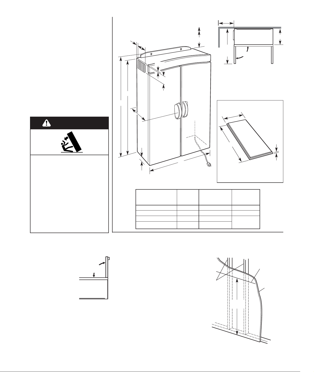
overall depth
for all models
(incl. handle)
panel
except PVFE600 weight A dimensions
white doors 117 lbs. 15-1/4" —
biscuit doors 117 lbs. 15-1/4" —
wood panel doors 137 lbs. 15-1/8" 17-1/16" x
mirrored doors 143 lbs. 15-1/8"
Product dimensions
Custom panels
PAGE 3
Parts not supplied
for installation:
• 2, 1/4"x1-1/4" lag bolts with wall
anchors for concrete or concrete
block wall installations.
Note: Lag bolt length is based on
mounting bracket thickness only.
Add thickness of any wall coverings
to length of lag bolts/wall anchors
used. These can be obtained from
local hardware store.
• 2, 1/4-20x3" toggle bolts and spring
nuts for metal studded walls. These
can be obtained from local
hardware store.
35"
6 ft. power supply cord.
3-prong ground-type outlet
must be located within 5
feet of lower right corner.
Cut door panel as shown. If the
desired panel is greater than 1/4"
thick, rout a 1/4" thick edge, in 1/4"
from all four edges.
1" minimum
clearance
required at
bottom of
vitalizer for
ventilation.
57"
7/16"
9/16"
5-7/8"
8-7/8"
59"
A
30-1/4"
both
doors
90°
12"
*
* 12" minimum clearance to side wall
on left side of appliance is required
for air venting.
** 24" minimum clearance to ceiling or
any non-removable object (cabinet,
soffit, shelf, etc.) above vitalizer is
required for serviceability.
1. With clothes
vitalizer in carton, lay
carton on back. Open
doors no more than
90° to avoid
damaging door hinges
and remove contents.
Important: Follow
removal instructions
printed on front of accessory box.
If installing model PVFE600, or if a
custom door panel is to be installed
on models PVWC600, PVWS600,
PVBC600, PVBS600, see "Product
dimensions" on this page for custom
panel size and then go to “Installing
custom door panels” on Page 5.
Note: It is not recommended to
customize mirrored models
PVWM600 or PVBM600.
Now start...
Installation steps
Tip Over Hazard
Do not use clothes vitalizer until
completely installed.
Install lag bolts securely into
wall studs.
Use two or more people to move
and install clothes vitalizer.
Reapply tape or strap to secure
doors before moving clothes
vitalizer.
Failure to follow these
instructions can result in death
or serious injury.
WARNING
90°
maximum
Model shown:
PVWN600
wood
studs
line
(must be level)
wall
70-3/4"
min.
24"**
11-1/4"
52-13/16" x
1/4" thick
2.Shut doors and reapply tape or
strap. Leave clothes vitalizer in box.
3.Remove the mounting bracket
assembly, nuts and lag bolts (if
installing in wall studs) from the
accessory box.
With washer sides of nuts facing
mounting bracket, start nuts onto the
bracket's threaded studs.
4.Mark a horizontal line at least
24 inches long, 70-3/4" minimum
from the floor. Important: The line
MUST be level.
For wood stud installations,
go to Step 5.
For metal studded wall
installations, go to Step 6.
For concrete of concrete block
installations, go to Step 7.
For models
PVFE600,
PVWC600,
PVWS600,
PVBC600,
PVBS600:
1/4"
52-13/16"
17-1/16"

toggle
bolt
spring
nut
toggle
bolt
bracket
assembly
Critical step:
For wood stud installations, each lag
bolt MUST be installed in a wood stud.
If there are not 2 studs in mounting
area, DO NOT install vitalizer.
DO NOT use toggle bolts through
dry wall to support the clothes
vitalizer.
5a. Locate and mark the centers
of each wall stud. Make these marks
about 72" from the floor.
align edge
with level line
1/4-20 nuts
5b. Align the lower edge of the
mounting bracket assembly with the
level horizontal line. Select and mark
a hole location on each side of the
bracket that is closest to the center of
each stud. Mark the holes to be used
on the bracket assembly also.
5c. Set bracket aside and drill
5/32" pilot holes.
5d. Fasten the mounting bracket
to wall. Check that the bracket is
level then securely tighten the lag
bolts.
Go to Step 8.
align edge
with level line
1/4-20 nuts
6b. Align the lower edge of the
mounting bracket assembly with the
level horizontal line. Select and mark
a hole location on each side of the
bracket that is closest to the center of
each stud. Mark the holes to be used
on the bracket assembly also.
6c. Set bracket aside and drill
5/32" pilot holes.
6d. Drill 3/4" holes for spring nuts
to slide through.
wood
stud
wood stud
center
wall
Critical step:
For metal studded wall installations,
each bolt MUST be installed in a metal
stud. If there are not 2 studs in
mounting area, DO NOT install
vitalizer.
DO NOT use toggle bolts through
dry wall to support the clothes
vitalizer.
6a. Use a magnetic stud finder to
locate and mark the centers of each
metal wall stud. Make these marks
about 72" from the floor.
6e. Insert 1/4-20 x 3" toggle bolts
through the selected holes in the
bracket assembly. Start a spring nut
on each toggle bolt. Leave enough
space for the spring nut to go
through the wall and stud and open
up behind the stud.
6g. Lightly tighten the toggle bolts.
Check that the mounting bracket
assembly is level. Securely tighten
the toggle bolts.
Go to Step 8.
6f. Position the mounting bracket
assembly on the wall and push the
toggle bolt and spring nut assemblies
through the wall and metal stud. Pull
the toggle bolt towards you and
finger tighten to insure that spring
nuts have opened fully against metal
stud.
metal
stud
metal stud
center
wall
5.Wood stud installations: 6.Metal studded wall
installations:
7.Concrete or concrete block
wall installations:
metal stud
mounting
bracket
assembly
7a. Align the lower edge of the
mounting bracket assembly with the
level horizontal line. Select and mark
a hole location on each side of the
bracket.
7b. Set bracket aside and drill
holes. Drive the wall anchors into
the holes with hammer.
7c. Fasten the mounting bracket
to wall. Check that the bracket is
level then securely tighten the lag
bolts.
8.Space the mounting bracket
nuts 1/2" to 3/8" away from mounting
bracket.
1/2" to
3/8"
mounting
bracket
nut
mounting
bracket
wood stud
shown
PAGE 4

9.Lift clothes vitalizer up and
slide keyhole slots over nuts. Lower
vitalizer down onto mounting bracket
studs and tighten nuts. Remove tape
or strap from doors.
10.Check tops of doors for
uniform vertical alignment. Wall
irregularities may require shimming
the back bottom corners of the
cabinet away from wall to align the
door tops.
If door tops are not aligned:
• Carefully pull a bottom cabinet
corner away from the wall and
observe the alignment shift.
• Separate adhesive backed spacers
(in accessory box) but do not
remove from the adhesive backing.
• Insert spacers at either or both
bottom corners to obtain door
alignment. The spacers may be
stacked for additional thickness if
needed.
• When alignment is obtained,
remove the spacers from the
adhesive backing and attach to
back of cabinet.
stud
mounting
flange
slot
adhesive
protective strips
flat side must
face up
drain openings
spacers as
needed
Model shown:
PVWN600
11. Remove mounting bracket
cover from accessory box. Peel off
adhesive protective strips. Align
cover with bracket and press cover
against bracket.
Note: Mounting bracket cover can be
painted or covered with wallpaper.
12. Remove collection basin
cover from accessory box. With flat
side facing up, place into depression
in bottom of inner liner.
13. Plug power supply cord into
grounded outlet.
14. If your clothes vitalizer
came with a storage drawer, follow
the instructions packed with the
drawer and install it now.
PAGE 5
Installing custom door panels
Door removal:
Custom panel installation:
1. Use 11/32” wrench and remove
acorn nuts on each end on of drip
tray. Use 1/4“ nut driver or wrench
and remove 4 hex head screws from
drip tray. Remove drip tray and set
aside along with acorn nuts and
screws.
1. Lay protective material such as
a blanket or cardboard that is slightly
larger than the door on floor or any
flat support surface.
2.Lay a door on protective
surface with door handle facing up.
2.Open door 90°. Support door in
this position and use Phillips
screwdriver to remove both screws
from lower door hinge. Set screws
and lower hinge aside.
3.Slide door out of upper hinge
and set aside. Remove plastic
shoulder washer from upper hinge
pin and set aside. Do not lose this
washer.
Remove other door.
3.Use Phillips screwdriver and
remove 3 screws from top end cap.
(This is same end cap from which
shoulder washer was removed.)
Remove end cap and set aside. Do
not lose the 3 plastic spacers on the
screws.
Important: If you are installing
models PVWC600, PVWS600,
PVBC600, PVBS600, remove and
discard the door panel that came
with your model. Model PVFE600
does NOT come with panels.
4.Slide custom door panel into
door channels until it fits snugly
under edge of door’s bottom end
cap.
5.Reassemble top door end cap.
Make sure that the 3 plastic spacers
are on screws.
Repeat to install custom panel in
other door.
acorn nut
hex head
screw
drip tray
lower
door
hinge
screws
screws
top
end cap
plastic spacers

Part No.8527389
©2002 Whirlpool Corporation Printed in U.S.A.
Benton Harbor, Michigan 49022
If clothes vitalizer
does not operate:
• Check that circuit breaker is not
tripped or house fuse blown.
• Check that power supply cord is
plugged into wall outlet.
• See Owner's Manual for
troubleshooting list.
If you need
assistance:
• Refer to Owner's Manual.
• Call the Consumer Interaction
Center. Check your Owner's
Manual for a toll-free number to call
or call the dealer from whom you
purchased the clothes vitalizer. The
dealer is listed in the Yellow Pages
of your phone directory under
“Appliances –Household – Major —
Service and Repair.”
Accessories:
The following storage drawer kits are
available from your dealer:
Kit No. 8527309 White
Kit No. 8527310 Biscuit
Kit No. 8527308 Signet Grey
If you need service:
Maintain the quality built into your
clothes vitalizer by calling an
authorized service company.
To obtain the name and number of
an authorized service company:
• Contact the dealer from whom you
purchased your clothes vitalizer, or
• Look in the Yellow Pages of your
phone directory under “Appliances
–Household – Major — Service and
Repair,” or
• Call the Consumer Interaction
Center. The toll-free number is
listed in your Owner's Manual.
When you call, y ou
will need:
• The clothes vitalizer model number.
• The clothes vitalizer serial number.
Both numbers are listed on the
model/serial number plate located on
the lower cabinet frame next to the
door magnet.
Reassemble doors to clothes
vitalizer:
1. Place plastic shoulder washer
on upper door hinge pin. Support
door in 90º open position and slide
door into upper hinge.
lower
door
hinge
screws
2.With door still in 90° open
position, reattach lower door hinge.
Use Phillips screwdriver to reinstall
both lower door hinge screws.
Securely tighten screws.
acorn nut
hex head
screw
drip tray
3.Reattach drip tray. Reinstall 4
hex head screws and 2 acorn nuts,
one on each end of drip tray.
Tighten securely.
Repeat to install other door.
4.Shut doors and reapply tape or
strap. Leave clothes vitalizer in
carton and go back to Step 2 of
"Installation steps" on Page 3 to
complete installation.
Important: Before vitalizer is
installed, do not open doors more
than 90° to avoid damaging door
hinges.
 Loading...