


INAV-RRL (Page 1 of 2) 120918
Roof Rails and Truck Bed Rails
Installation Instructions
CAUTION: Do not use the mounting hardware contained in this unit to install rails on Fiberglass or Composite
Plastic surfaces. Supplemental hardware pack, part# HWAVTC-UV, is required for installing rails on such nonmetal surfaces. Please contact the Distributor from whom the unit was purchased or contact the Perrycraft
Customer Service Dept at 800-777-7081 to obtain the necessary supplemental hardware pack if installing these
roof rails on a Fiberglass or Composite Plastic surface.
CONTENTS: 2 - side rails, 2 - Left end supports and mating covers; 2 - Right end supports and mating covers;
Center Support Posts: 2-posts in 68" & 78" Roof Rails, 4-posts in 88" Roof Rails and all Bed Rails;
1 hardware pack (Containing 4-#8x5/8 self-threading screws; 12-#10x3/4 waxed-tip pan head
screws; 4-1/4 Stainless Steel Flat Washers; #10x1 Waxed-tip Oval-head Screws: 2-screws in
68" & 78" Roof Rails, 4-screws in 88" Roof Rails and all Bed Rails; and 1-instruction sheet).
Tools required: Phillips screwdriver; electric drill; 1/8 drill bit; center punch; pencil or marker.
For Truck Bed Rail installation, skip to Step 2.
1) As universal Roof Rails are designed to fit several different vehicles, the bow / curvature of the side rails
may not exactly match the roof contour of a particular vehicle. NOTE: The rails should be dry fit to the
roof panel before installing. Carefully place one of the rails (without end supports or center support posts)
on the vehicle roof in the approximate location to be installed. The curvature of the rail should approximate
the roof contour. If rail is under-curved and there is more than a 3/16 space between the ends of the rail
and the vehicle roof panel, or over-curved and there is more than a 3/16 space between the center of the
rail and the roof panel, bench adjusting the curvature of the rails is required. Adjust by suspending the rail
between two points (4x4 wooden blocks, two tables, etc). To increase the curvature, start with the rail upside
down; to decrease the curvature, start with the rail right side up (see appropriate illustration below). With
hands spaced shoulder-width apart, apply sufficient pressure to the rail to increase or decrease the curvature
as desired. Repeat this process for both rails.
Important Note: While made of extruded aluminum, the rails are heat-treated for added strength.
Therefore, several applications of adequate springing pressure may be required to modify the curvature
of the rails.
Increase Rail Curvature-Rail Upside Down
2) Slide center posts into groove on bottom
of rails (applicable only on rails of 68 or
longer).
Side
Rail
#10x1
Oval-head
Waxed
Screw
Decrease Rail Curvature-Rail Right Side Up
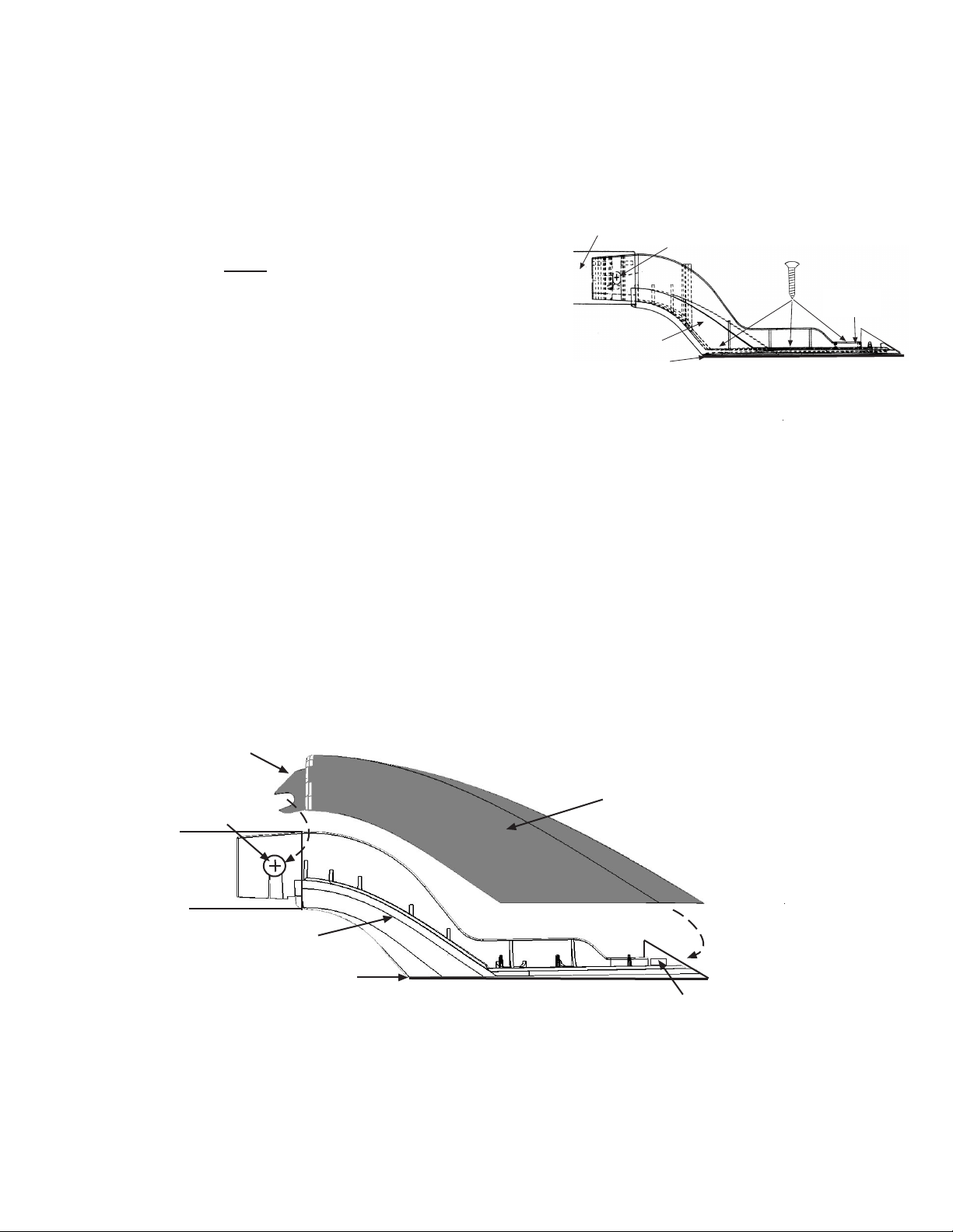
3) Install end supports to side rails using the #8 x 5/8
self-threading screws. Do not tighten screws
completely at this point.
Side Rail
#8x5/8" Screw
Center
Post
Neoprene
Pad
Support
Base
(A-L or A-R)
(over)
INAV-RRL (Page 2 of 2) 120918
4) Place assembled rails in desired position on vehicle roof. If center posts are included in the unit, the post
should be positioned approximately midway along the length of the rails. Mark locations of all mounting
holes. Remove rails from roof.
5) Lightly center punch each marked mounting hole location. Drill fastener pilot holes using 1/8 drill bit taking
care not to allow drill bit to penetrate vehicle headliner. Clear all metal drill chips from roof panel and apply
a coat of primer or rust inhibitor to the bare metal edges of each hole.
6) Reposition rails on roof panel and install using the #10 x
3/4 waxed screws.
NOTE: At outer most hole in each
end support, use a 1/4 Stainless Steel flat washer (included)
under head of each screw. Note: use #10 x 1 Oval Head
waxed screws to secure center posts as shown in illustration
on Page 1.
Side Rail
Support Base
(A-R or A-L)
Neoprene Pad
#8 x 5/8 Screw
#10x3/4
Waxed Screws
1/4 S. Steel
Flat Washer
Nylon
Washer
7) Loosen the #8 x 5/8 support-to-rail screws approximately 2-3 complete turns to allow installation of the
support covers.
8)
Position a mating support cover (A-L cover to A-L support; A-R cover to A-R support) as shown in diagram
below with the vertical blade of the cover sliding into the gap between the side wall of the end support tongue
and the center wall of the rail extrusion. With blade correctly inserted/aligned at the end of rail, rotate the
cover downward until it contacts the support base, and apply moderate downward pressure at the tapered
end of the cover until the lock tabs at the end of the cover snap into the mating tab slots at the end of
the support base.
9) With covers properly installed, securely tighten the four #8 x 5/8" support-to-rail screws while applying slight
pressure to the top of each cover to insure proper seating of the cover to the mating support base.
Slide vertical blade of cover into gap between base and wall of side
rail, insuring slot in blade seats around shank of screw. Rotate
opposite end of cover downward until it contacts the support base,
then apply moderate pressure at the end until cover snaps into tab
slots at end of base.
Vertical
Blade
#8x5/8"
Screw
Support Cover
(mate A-L or A-R)
Side
Rail
Support Base
(A-L or A-R)
Neoprene Pad
Mating Tab Slot
IMPORTANT NOTE: This Roof Rail/Bed Rail Kit contains 4 Rail Supports with mating Right and Left
Bases and Covers. These components are identified by "A-L" or "A-R" molded on the top surface
of each Base and inside surface of each Cover. When installing Covers, insure that Covers are
mated with appropriate Bases.
 Loading...