

Page 1
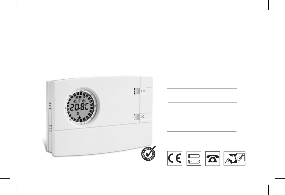
CRONOTERMOSTATO DIGITALE DA PARETE
WALL MOUNTING DIGITAL CHRONOTHERMOSTAT
CHRONOTHERMOSTAT DIGITAL POUR MONTAGE EN SAILLIE
DIGITAL RAUMTHERMOSTATUHR WANDMONTAGE
CRONOTERMOSTATO DIGITAL DE SUPERFICIE
Modello giornaliero
Modello settimanale
Daily model
Weekly model
.
Modèle journalier
Modèle hebdomadaire
Modell mit Tagesprogramm
Modell mit Wochenprogramm
Modelo diario
Modelo semanal
PE - DECRNN034 12/10
Page 2

- Italiano
IT
DATI TECNICI - ISTRUZIONI PER L’INSTALLAZIONE
MODO D’IMPIEGO - AVVERTENZE
Pagina 3
G
- English
F
EN
B
D
- Français
FR
- Deutsch
DE
- Español
ES
2
TECHNICAL DATA - INSTALLATION GUIDELINES
USER INSTRUCTIONS - WARNINGS
DONNÉES TECHNIQUES - NORMES D’INSTALLATION
MODE D’EMPLOI - AVERTISSEMENTS
TECHNISCHE DATEN - NORMEN FÜR DIE INSTALLATION
BEDIENUNGSANLEITUNG - HINWEISE
DATOS TÉCNICOS - NORMAS DE INSTALACIÓN
INSTRUCCIONES PARA EL USUARIO - ADVERTENCIAS
Page 14
Page 25
Seite 36
Página 47
Page 3

1 - DATI TECNICI
Tensione di alimentazione:
Autonomia:
Autonomia dall’accensione del simbolo pile scariche:
Tipo di azione, disconnessione ed apparecchio:
Software:
Tensione impulsiva nominale:
Tipo di uscita:
Sezione dei fili ai morsetti relè:
Ingresso per programmatore telefonico:
Sezione dei fili ai morsetti programmatore telefonico:
Tipo di isolamento:
Grado di protezione:
N° indici programmabili sulla corona dell’orologio:
Tempo minimo programmabile con tasti “cavaliere”:
Grado inquinamento:
Scala regolazione temperatura tramite manopole:
- Comfort:
t
- Riduzione (risparmio):
t
Limitazione di temperatura (blocco set t max.):
Temperatura antigelo ( ):
Precisione di regolazione della temperatura:
Scala di visualizzazione temperatura ambiente:
Tolleranza lettura della temperatura ambiente
Limiti della temperatura di funzionamento:
Limiti della temperatura di stoccaggio:
Gradiente termico:
Tipo di regolazione della temperatura:
Precisione dell’orologio:
Normative di riferimento per marcatura CE:
t
n° 2 pile alcaline Stilo 1,5 V tipo AA LR6
2 anni
1 mese
1 / BU / Elettronico
classe A
4 kV
a relè con contatto in scambio NA / COM / NC
libero da potenziale - max 5(3)A / 250 Vac
0,75 ÷ 2,5 mm
per contatto NA libero da potenziale
0,5 ÷ 1,5 mm
classe II
IP 30
48
½ h
normale
+5 ÷ +30 °C (default +20 °C) / +41 ÷ +86 °F (default +68 °F)
+5 ÷ +30 °C (default +17 °C) / +41 ÷ +86 °F (default +62,6 °F)
Step 0,1°C / 0 ,1 °F
+5 °C / 41 °F (fissa non regolabile)
± 0,1 °C / ± 0,1 °F
0 ÷ +50 °C / +32 ÷ +122 °F
± 0,5 °C / ± 0,9 °F
0 ÷ +50 °C / +32 ÷ +122 °F
-20 ÷ +65 °C / -4 ÷ +149 °F
max 1K / 15 min.
funzionamento ON-OFF con differenziale impostabile a 0,3 - 0,5 - 0,7 - 0,9 °C
funzionamento proporzionale con cicli di tempo impostabili 7-10-15-20 minuti
± 1 sec/gg
LVD e EMC EN60730-2-7 EN60730-2-9
2
2
(consigliate pile DURACELL o ENERGIZER)
IT
3
Page 4
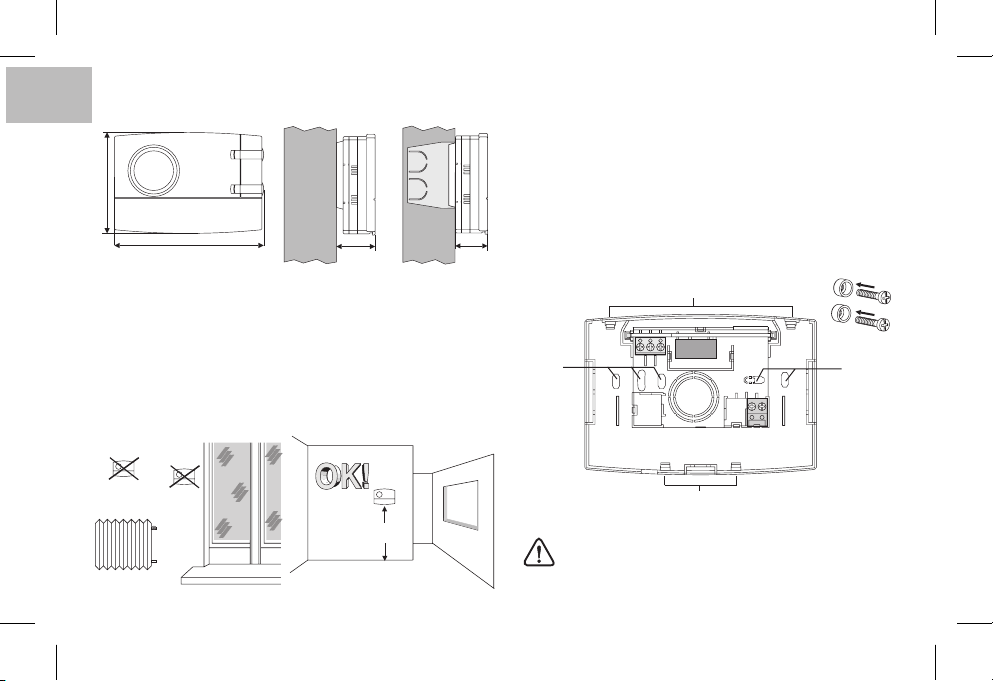
2 - DIMENSIONI D’INGOMBRO
IT
82
121,5
31,5 26
3 - NORME PER L’INSTALLAZIONE
Installazione delcronotermostato: indipendente -fisso
A parete - su scatolatonda - asemincasso su scatola rettangolare 3
moduli.
Installare il dispositivo a circa 1,5 ÷ 1,6 m da terra lontano da fonti di
calore, finestree quant’altro possainfluenzare ilnormale stato operativo.
4 - FISSAGGIO DELLA BASE A PARETE
Disattivare latensione di retedel dispositivoda pilotare
Fissare con le viti la base: a muro, alla scatola da incasso tonda o
rettangolare utilizzandole opportune coppiedi fori .A
Qualora la parete dove fissare la base del cronotermostato fosse
metallica, inserirenelle due vitile appositerondelle isolanti.
A - fori di fissaggio
B - passaggio fili da scatola tonda, rettangolare
C - dentini di fissaggio del cronotermostato
C
3
A
21
A
4
5
6789
B
!
h 1,5 m
4
Per assicurare un corretto montaggio del
cronotermostato alla basea parete,la stessa non deve
presentare incurvature dovute all’eccessivo serraggio
delle viti di fissaggio alla scatola rettangolare o tonda
incassata a muro.
C
Page 5
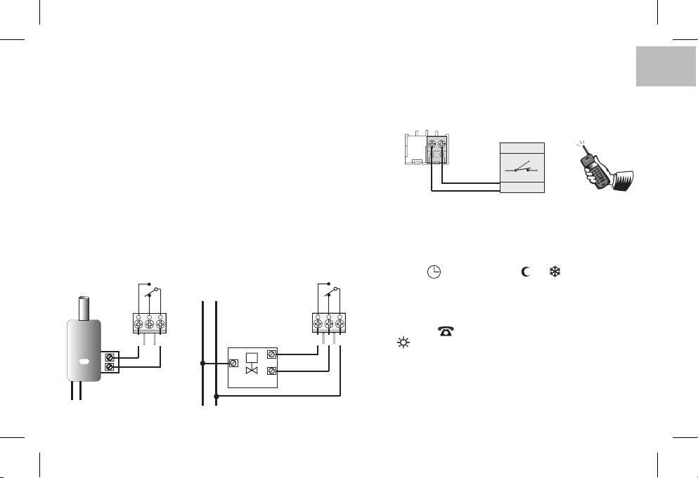
5 - COLLEGAMENTI ELETTRICI
Importante: l’installazione ed il collegamento elettrico dei dispositivi
ed apparecchiature devono essere eseguiti da personale qualificato
ed in conformità alle norme e leggi vigenti. Il costruttore non si assume alcuna responsabilità per quanto concerne l’impiego di prodotti
che debbanoseguire particolarinorme diambiente e/o installazione.
Nota perl’installatore: nel casodi montaggiosu superficie(es. a parete), prevedere adeguata canalizzazione dei cablaggi nel rispetto delle
vigenti normed’impianto.
Verificareche il caricodel relè nonsuperi ilvalore indicato neidati tecnici.
Disattivare la tensione di rete del dispositivo da comandare.
Collegare il dispositivo da comandare ai morsetti:
1-comune
2-3-contatto normalmente chiuso
contatto normalmente aperto
Esempi di collegamenti elettrici
Collegamento ad una caldaia
NA
C
NC
CALDAIA
231
L
N
230V~
Collegamento ad
una valvola motorizzata
230V~
N
L
M
CARICO
APRE
CHIUDE
NA
NC
231
Collegamento di un programmatore telefonico per
controllo remoto
I morsetti e del cronotermostato sono predisposti per il
collegamento di un programmatore telefonico con contatto
normalmente aperto.
89
6789
esempio:
programmatore telefonico
Contatto
Funzionamento con programmatore telefonico
Il programmatore telefonico comanda il cronotermostato
chiudendo il contattocollegato ai morsetti e .89
Per attivare il cronotermostato tramite programmatore telefonico
è necessario impostare il commutatore in uno dei seguenti tipidi
funzionamento: AUTOMATICO o o .
Quando ilprogrammatore vieneattivato (contattoai morsetti8 e 9
C
chiuso) il cronotermostato passa da una delle condizioni
impostate con il commutatore
temperatura comfort
sul display oltre a tutti i 48 indici accesi,
t
t
a funzionamento:sempre in
appare il simbolo di programmatore telefonico attivato e il
simbolo lampeggiante di Comfort.
Disattivazione della forzaturada programmatore telefonico
Aprire il contatto del programmatore telefonico (vedere istruzioni
del programmatore) che riporta il cronotermostato al modo di
funzionamento presente almomento dell'attivazione.
Nota: i comandidi attivazionee disattivazionesono operativientro 1 minuto.
IT
5
Page 6
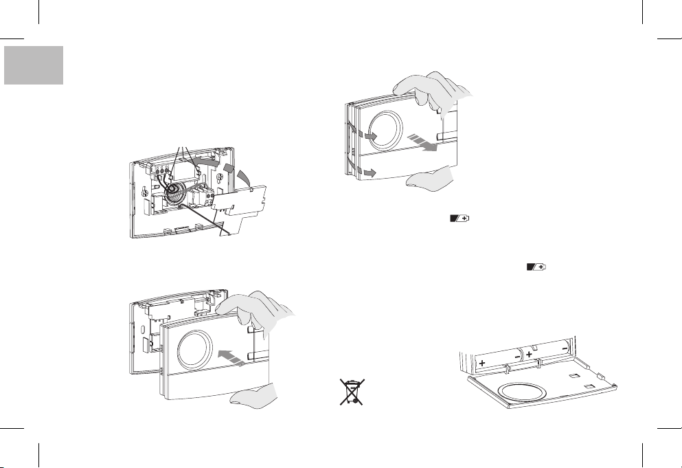
6 - FISSAGGIO O RIMOZIONE DEL CRONOTERMOSTATO DALLA BASE
IT
Applicare il coperchietto copri cavi inserendo il dentino
nell’apposita cava della base, quindi fissarlo con una leggera
pressione nei ganci .
E
F
D
Per rimuovere il coperchietto utilizzare un piccolo cacciavite
facendo leva insuccessione su ciascungancio .
F
F
Per rimuovere il cronotermostato
dalla base a parete, afferrarlo
come in figura, quindi estrarlo
facendolo ruotare sullato destro.
E
D
Agganciare il cronotermostato alla base avendo cura di inserire
correttamente icontatti, quindi esercitare una leggerapressione
sino ad udirelo scatto deidentini di fissaggio.
6
7- INSERIMENTO O SOSTITUZIONE PILE
La comparsa del simbolo indica che le pile si
stanno esaurendo; da questo momento si hanno circa 30 giorni di
tempoper effettuarela sostituzione.
Se non si sostituiscono le pile quasi scariche nei tempi dichiarati si
spegneràil displayvisualizzando soloil simbolo fisso.
Ogni attività di termoregolazione viene sospesa e tutte le impostazioni
vengonomemorizzate peressere ripristinateall’inserimentodelle nuovepile.
Sostituire le pile esaurite con due pile 1,5 V tipo AA
(LR6)
prestando attenzione alle polarità.
ATTENZIONE: nel caso di sostituzione delle pile, il tempo a
disposizione per l’operazionesenza
perdere i datiè di circa
1 minuto.
Smaltire le pile esauste
gettandole negli
appositi contenitori.
lampeggiante
Stilo alcaline
Page 7
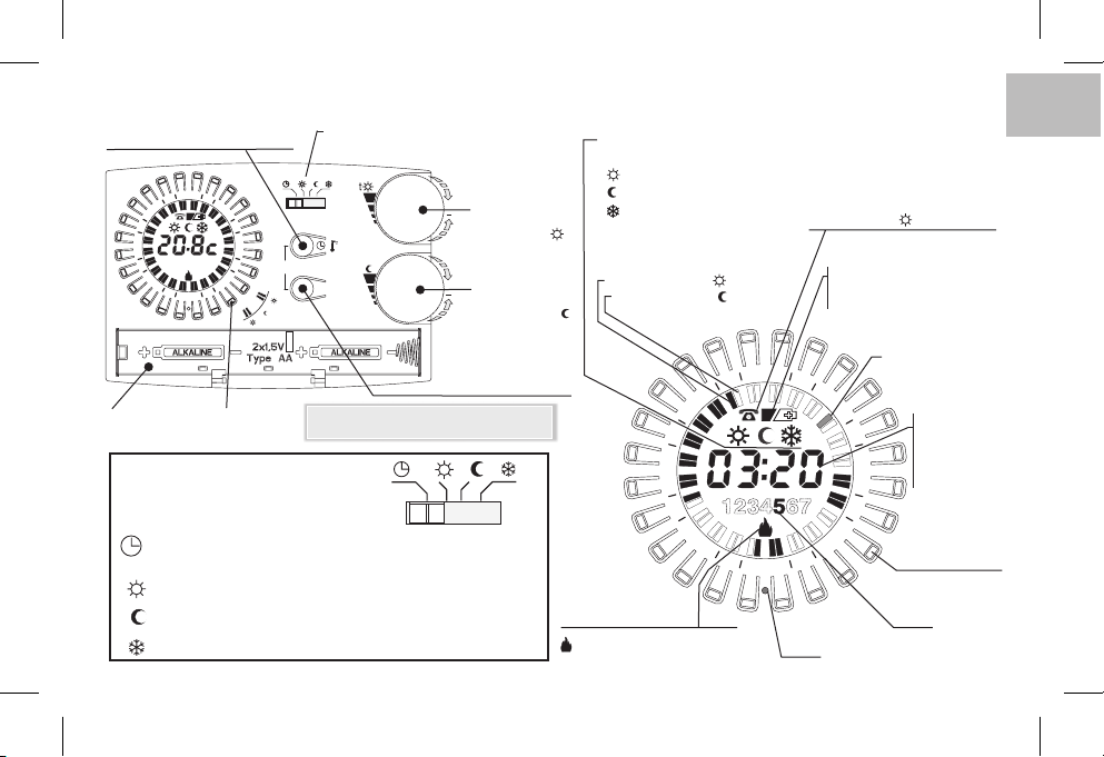
8 - VISTA GENERALE, LEGENDA DISPLAY E FUNZIONI TASTI
Tasto impostazione: ore-minuti
o visual. Temperatura ambiente
4
2
8
1
Vano pile
21
15
1234567
2
1
R
3
6
9
Tasto
“cavaliere”
t
TIPO DI FUNZIONAMENTO
SELEZIONABILE TRAMITE
COMMUTATORE
AUTOMATICO - Comfort o Riduzione regolabili da5a30°C;
Sempre ,Comfort regolabile da5a30°C(tutti i 48 indici accesi)
t
Sempre ,Riduzione regolabile da5a30°C(tutti i 48 indici spenti)
t
Sempre ,Antigelo temperatura fissaa5°C(tutti i 48 indici spenti)
t
secondo programmazione degli indici con tasti cavaliere
Commutatore - tipo modalità di funzionamento
(vedere dettaglio nel riquadro sotto)
t
t
t
/
copy
t
t
t
Day
Nota: ulterioriparticolari funzionidei tasti sono
descritte negli specifici paragrafi di utilizzo.
(5 ÷ 30 °C)
Manopola reg.
+
temperatura di
Set comfort
Manopola reg.
+
temperatura di
Set riduzione
Tasto selezione giorno
(solo mod. settimanale)
(5 ÷ 30 °C)
(risparmio)
t
t
ttt
Visualizzazione del tipo
di funzionamento in corso:
Comfort
Riduzione
Antigelo
Visualizzazione del
programma inserito
Indice acceso = t comfort
Indice spento = t riduzione
1
Indicatore stato utenza
lampeggiante = relè attivato
spento = relè disattivato
IT
Attivazione tramite
programmatore telefonico
(con indicatore lampeggiante)
Indicatore pile:
- quasi scariche
- scariche
4
2
21
8
15
1
3
6
9
2
R
Reset
(lampeggiante)
(fisso)
Indice 1/2h corrente
lampeggiante
Ora corrente o
temperatura
ambiente rilevata
/ set temperatura
in impostazione
Tasto “cavaliere”
Giorno
(mod. Settimanale)
es. 5 = Venerdì
7
Page 8
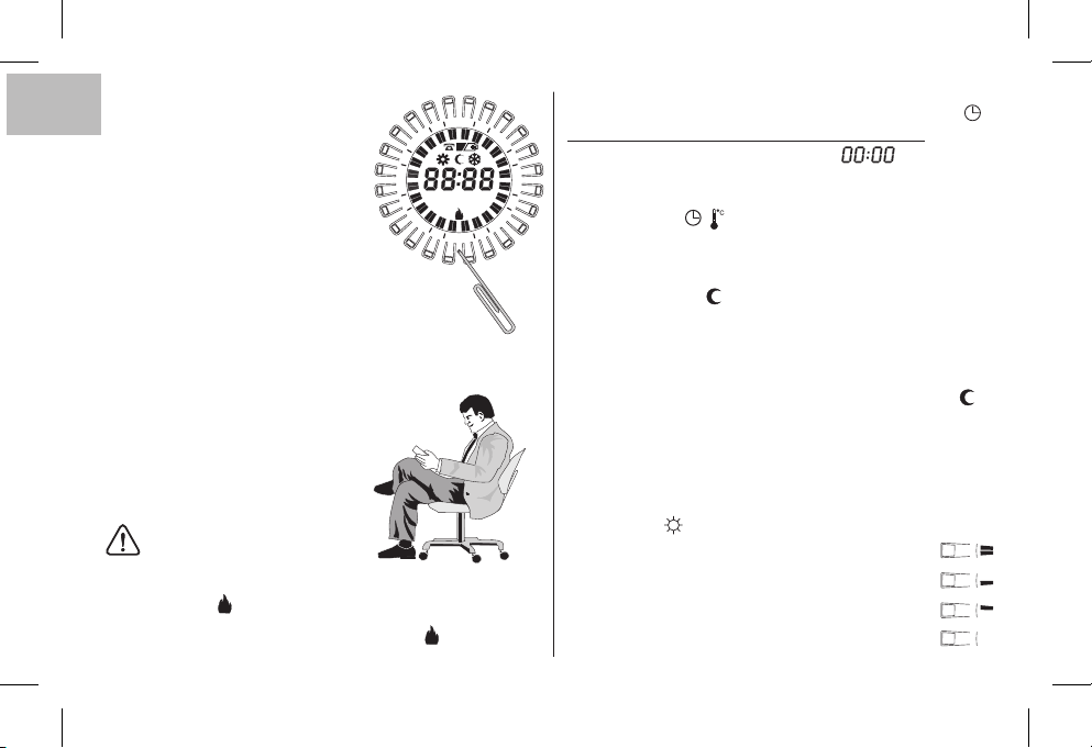
9 - RESET
IT
Alla prima accensioneRo nel caso in
cui il cronotermostatopresentasse delle visualizzazioni anomale, errato funzionamento, ecc., inserire una sottile
astina (max 1 mm) nel foro posto sulla
corona tra i tasti “cavaliere” e contrassegnato da quindi premere brevemente. Il display accenderà tutti i segmenti peralcuni secondi comein figura
4
2
21
8
1
15
123 6745123 674
3
9
1
2
R
a lato etutti idati presenti nella memoria
verranno cancellati ripristinando le impostazioni difabbrica (escluse leimpostazioni con imicrointerruttori).
Il cronotermostato sarà pronto per una nuova programmazione
(vedere Capitolo 10).
Programmazione facilitata
Tutte le operazioni descritte nel
paragrafo che segue possono essere
effettuate prima difissare il cronotermostato allabase a parete;ciò consente di
effettuare la programmazione stando
comodamente seduti.
ATTENZIONE !
Qualora la programmazione del cronotermostato avvenga prima del fissaggio
alla base parete, ad installazione ultimata potrebbe verificarsi che l’indicazione
presente suldisplay (spenta olampeggiante) noncorrisponda allo stato reale
del relè. Entro dal fissaggio delcronotermostato alla base parete,
il relèsi attiverà secondol’indicazione presente sul display (spenta o lampeggiante).
8
max 1 minuto
10 - PROGRAMMAZIONE
Posizionareil commutatoresu funzionamento .
IMPORTANTE:eseguire l’operazionedi RESET
Dopo alcuni secondi il display visualizza lampeggianti,
inserire ora eminuti attuali comedescritto di seguito.
6
Inserimento ore eminuti attuali
Premere il tasto per programmare l’ora:
- tenendo premutosi regolanole ore;
- premendo adimpulsi siregolano iminuti;
(sul modello giornaliero, attendere 5 secondi la comparsa sul
display del simbolo e l’indice della ½ h lampeggiante corrispondente all’ora programmata).
Inserimento giornoattuale
Il displayvisualizza il giorno lampeggiante corrispondente al .1 Lunedì
Premere il tasto per selezionare il giorno attuale della
settimana (attendere 5 secondi la comparsa del simbolo
l’indice della mezz’ora lampeggiante corrispondente all’ora
programmata).
Programmazione temperaturacomfort agliorari desiderati
Premere e rilasciare
display corrispondenti alle ore in cui si intende attivare la
temperatura comfort (livello di temperatura impostato con la
manopola ), agendo nelmodo seguente:
1° pressione erilascio per attivarel’intera ora
2° pressione erilascio perattivare laprima mezz’ora
3° pressione e rilascio per attivare la seconda mezz’ora
4° pressione erilascio per disattivarel’intera ora
/
(solo permodello settimanale)
Day
i tasti “cavaliere” disposti a corona sul
t
AUTOMATICO
e
Page 9
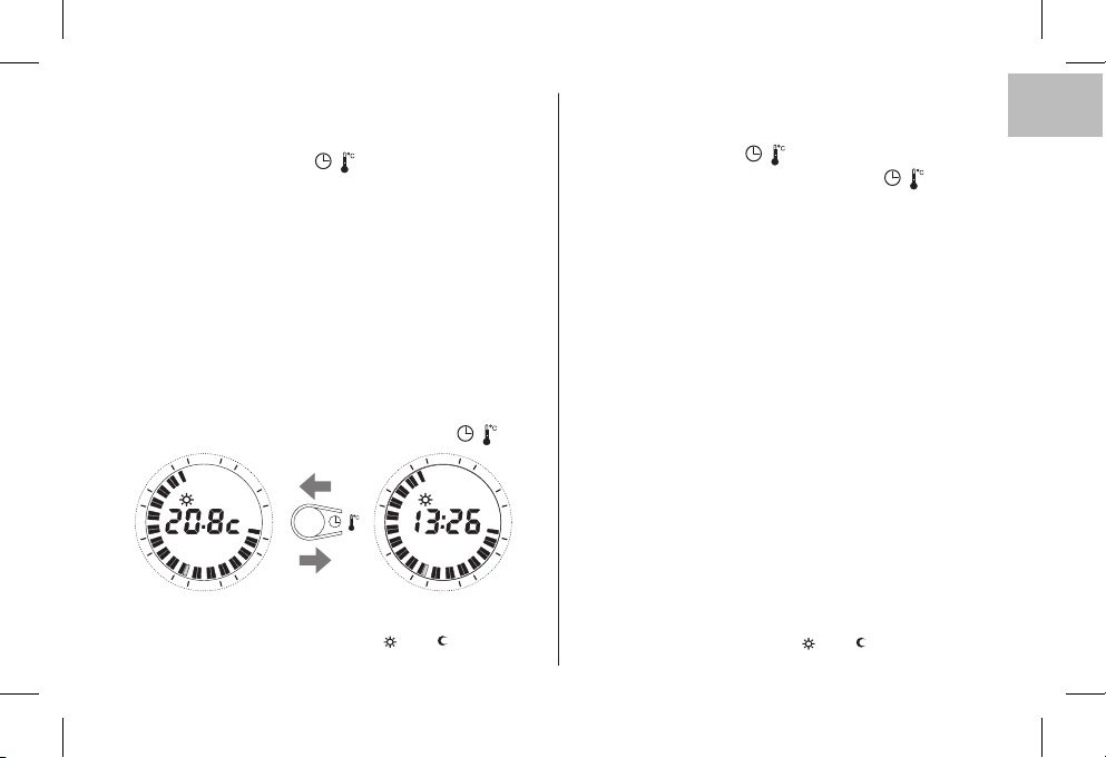
Copia del programmasu piùgiorni (soloper modello settimanale)
Dopo avere eseguito la programmazione del giorno è possibile
copiarla ( ) sul giorno successivo
contemporaneamente i tasti Day
Se si desidera impostare programmi diversi, scegliere il giorno
con il tasto quindi effettuare la programmazionepremendo i
tasti cavaliere comedescritto precedentemente.
copy premendo
e.
/
Day
Visualizzazione programmi inseriti relativi ai giorni della
settimana
(solo per modellosettimanale)
Premere e rilasciare ad impulsi il tasto .Day
Nota: al terminedelle operazioni di programmazione ovisualizzazioni, trascorsi 5 secondi dall’ultima azione sui tasti, si
il cronotermostato
posiziona automaticamentenello stato operativo(indice della½ h corrente lampeggiante).
In qualsiasi momento è possibile passare dalla visualizzazione sul
display dell’ora corrente alla temperatura ambiente (gradi
centigradi) e viceversa,premendo brevemente iltasto .
4
2
21
1
8
1
3
6
3
15
Visualizzazione Set ditemperatura t e/o t impostato
vedere paragrafo 11
9
2
1
1
21
8
1
/
15
/
4
2
3
6
3
9
2
21
1
MODIFICA IMPOSTAZIONI PROGRAMMATE
Modifica ora attuale
Tenere premuto il tasto fino al lampeggio dell’ora corrente
Modificare l’ora e/o minuti agendo sul tasto come
descritto precedentemente.
Modifica giorno attuale
Tenere premuto il tasto fino al lampeggio del numero
/
/
(solo per modellosettimanale)
Day
corrispondente al giorno corrente.
Impostare il nuovo giorno corrente premendo il tasto .
Day
Modifica programmi inseriti
Modello giornaliero
Modificare il programma agendo direttamente sui tasti
“cavaliere” come descrittoprecedentemente.
Modello settimanale
Modificare il programma del giorno corrente agendo
direttamente sui tasti “cavaliere” come descritto
precedentemente.
Per modificare il programma degli altri giorni della settimana,
selezionare il giorno desiderato premendo erilasciando il tasto
, dopodiché agire direttamente sui tasti “cavaliere” come
Day
descritto precedentemente.
Nota: al termine delle operazioni di modifica, trascorsi 5 secondi
dall’ultima azione sui tasti, il cronotermostato riprende automaticamente lostato operativo (indicedella ½h corrente lampeggiante).
Modifica Set ditemperatura t e/o t impostato
vedere paragrafo 11
IT
9
Page 10
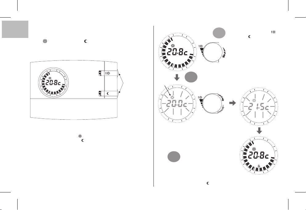
11 - VISUALIZZAZIONE/MODIFICA DELLE
IT
TEMPERATURE DI SET
(tramite manopole):
t COMFORT / t RIDUZIONE
Normalmente ildisplay visualizzala temperaturaambiente rilevata
o le oree minuti correnti.
4
2
21
3
8
1
15
6
3
9
1
2
t
alla prima accensione del cronotermostato, oppure dopo il
comando di reset,i Set ditemperature prefissati infabbrica sono:
Set Temperaturadi comfort t 20.0 °C/68.0 °F(manopola superiore)
Set Temperaturadi riduzione t = 17.0°C /62.6 °F(manopola inferiore)
=
In qualsiasi stato operativo si trovi il cronotermostato, per
visualizzare iset correntiè sufficenteruotare leggermente larelativa
manopola fino al lampeggio del set stesso, dopo 5 sec. il display
ritorna alla visualizzazionedel normale funzionamento.
Se i set impostati non soddisfano le Vostre necessità, si potranno
modificare a piacimentoin qualsiasi momentoda +5 °Ca +30 °C
(da +41 °Fa +86 °F),come da proceduraa lato.
10
10
Possibilità di ruotare
le manopole senza
aprile lo sportello.
Ruotare leggermente la
4
2
1
21
8
1
3
6
manopola desiderata
1°
comfort o riduzione) per
visualizzare il valore di
temperatura di Set corrente
ed entrarenella procedura di
regolazione.
t
3
15
Indicazione del
set in modifica
21
8
1
15
Nota: se è stato impostato un limite di temperatura (vedere
paragrafo successivo) il valoredi set può essere aumentato
fino atale limite (blocco).
3°
Eseguire la stessa procedura per impostare il Set di temperatura di
riduzione con lamanopola t
9
1
1
2
4
2
1
2
Il Set desiderato inizia a lampeggiare,
successivamente ruotare lamanopola in senso
orario peraumentare oppurein senso antiorario
2°
per diminuire(durante la rotazione siottiene una
variazione di 0.1°C/0.1°F allavolta).
3
6
9
La temperatura così
fissata sarà il nuovo Set
di riferimento.
Trascorsi 5 sec. dall'ultimo step
di rotazione della manopola, il
display torna alle condizioni di
normale funzionamento:
4
2
21
+
8
1
15
1
2
4
2
1
21
8
1
3
15
1
1
2
(
3
6
9
3
6
9
Page 11
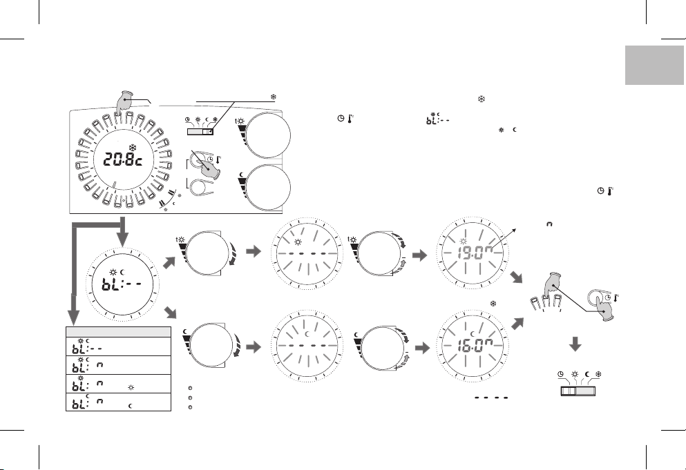
12 - LIMITAZIONE (BLOCCO) DEL SET MAX DI TEMPERATURA COMFORT E/O RIDUZIONE
In alcuni casi particolari di installazione del cronotermostato, ad esempio in edifici pubblici, alberghi ecc., potrebbe essere utile limitare i set di temperatura max in modo da evitare
impostazioni errate da parte di personale non autorizzato.
Tasto h23
8
1
8
1
21
12 45673
15
21
15
Premere insieme per 4 s.
4
2
3
9
2
1
R
4
2
3
9
1
2
Visualizzazioni possibili
Nessun blocco
(impostazione di fabbrica)
Blocco su
entrambi i set
Blocco solo
su set t comfor t
Blocco solo
su set t riduzione
6
6
Spostare il commutatore su t
t
t
t
/
copy
Day
t
t
t
e/o
Importante: dopo 20 sec. senza ruotare una delle manopole, il dispositivo esce automaticamente dalla
programmazione dei blocchi senza salvare alcuna impostazione esi pone infunzionamento antigelo(t )
t
Note:
nella configurazione di base non viene impostato alcun blocco.
per annullare eventuali blocchi precedentemente impostati riportare il/i Set a:
il comando di reset annulla eventuali blocchi impostati
t
Sarà quindipossibile limitare ivalori di Set(comfort e/o riduzione)di temperatura maxcome segue:
1
- Spostareil commutatore inmodalità antigelo t (set fissoa +5°C non modificabile)
2
- Premere contemporaneamente per4 sec. iltasto sulla corona corrispondentealle h23 eil
/
tasto , il displayvisualizza: (es. impostazione difabbrica= nessun blocco).
3
- Ruotare leggermente la manopoladel set desiderato (t t ) per visualizzare il set corrente.
4
- Il Set inizia a lampeggiare, dopo 3 sec. impostare il blocco (limitazione) da +5,1°C a
+29,9°C ruotando la manopolain senso orario per aumentare oppure insenso antiorario
per diminuire (durantela rotazione si ottieneuna variazione di 0,1°C allavolta).
5
- Se sidesidera, ripetere le operazioniindicate nei punti 3 e4 con l’altra manopola.
6
- Entro 20 sec, salvare l’impostazione/i ed uscire dalla programmazione, premendo con temporaneamente per 4sec. il tasto sullacorona corrispondentealle h23e il tasto .
7
- Riportare ilcommutatore sulla modalità difunzionamento desiderata.
4
2
21
8
1
15
21
8
1
15
3
6
9
2
1
4
2
3
t
6
9
2
1
+
+
21
8
1
15
21
8
1
15
o
4
2
2
1
4
2
2
1
Il simbolo indica temperatura max
3
limitabile, sia per la scala in °C che °F
6
Per salvare l’impostazione/i
ed uscire dalla programmazione
9
3
6
Riportare il commutatore sulla
modalità di funzionamento desiderata
9
42
Premere insieme
per 4 secondi
t
t
/
t
IT
/
11
Page 12
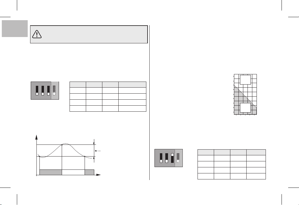
Le impostazioni dei microinterruttori (Dip-switch)
IT
posti sul retro del cronotermostato, devono essere
effettuate da personalequalificato.
13 - DIFFERENZIALE DI TEMPERATURA
Il cronotermostato funziona in modo differenziale ON-OFF
(Dip 3 in posizione OFF)con valore deldifferenziale prefissato
in fabbrica a (0,54°F).
Il valore del differenziale può essere modificato spostando i
microinterruttori (Dip-switch), comeindicato nella tabella.
ON
ON
Il valore del differenziale deve essere impostato in base all’inerzia
termica dell’impianto;si consiglia un valore bassoper impianticon
radiatori (es.in ghisa) edun valorealto per impiantocon fan-coil.
°C
Temperatura misurata
12
0,3 °C
ON
ON
Dip 1 Dip 2 Dip 3
OFF OFF OFF
32
1
32
1
4
OFF ON OFF
OFF
OFF
ON OFF OFF
ON ON OFF
Differenziale regolabile
0,3 °C - 0,5 °C - 0,7 °C - 0,9 °C
(0,54 °F - 0,9 °F - 1,26 °F - 1.62 °F)
OffOn On
Tempo
Differenziale
0,3 °C (0,54 °F)
0,5 °C (0,9 °F)
0,7 °C (1,26 °F)
0,9 °C (1,62 °F)
14 - FUNZIONAMENTO PROPORZIONALE
In alternativaal differenziale è possibile regolarela temperaturain
modo proporzionale (Dip 3 in posizione ON); questo sistema
permette di risparmiare sui consumi energetici ed anche
sull’usura del bruciatore limitandone le accensioni. La durata di
ogni accensione dipende oltre che dal ciclo impostato anche
dalla differenza tra la temperatura impostata e quella misurata
(vedi esempio).
Esempio di impostazione t =20 °C - Ciclo =10 min
t = 20,5 °C Utenza semprespenta
t = 20,4 °C Utenza 1min ON- 9min OFF
t = 20,3 °C Utenza 2min ON- 8min OFF
t = 20,2 °C Utenza 3min ON- 7min OFF
t = 20,1 °C Utenza 4min ON- 6min OFF
t = 20,0 °C Utenza 5min ON- 5min OFF
t = 19,9 °C Utenza 6min ON- 4min OFF
t = 19,8 °C Utenza 7min ON- 3min OFF
t = 19,7 °C Utenza 8min ON- 2min OFF
t = 19,6 °C Utenza 9min ON- 1min OFF
t = 19,5 °C Utenza sempreaccesa
La durata del ciclo è determinata dalla posizione dei microinterruttori (Dip-switch) posti sul retro del cronotermostato, come indicato
nella tabella. Si consiglia un ciclo lungo per impianti con inerzia
termica alta (radiatori in ghisa, impianti a pavimento) ed un ciclo
breve perimpianti con inerziatermica bassa(fan- coil).
ON
1
ON
Dip 1 Dip 2 Dip 3
OFF OFF ON
OFF
OFF ON ON
4
32
ON OFF ON
ON ON ON
°C
20,8
Utenza
OFF
20,6
20,4
20,2
20,0
19,8
19,6
Utenza
19,4
ON
19,2
01024 6 8 Minuti
Durata Ciclo
10 min
15 min
20 min
7 min
Page 13
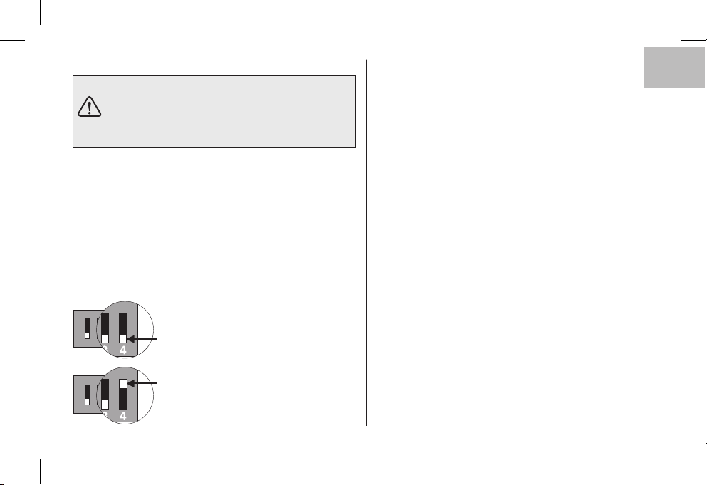
15 - SCALA DI TEMPERATURA °C o °F 16 - AVVERTENZE
ATTENZIONE:
il cronotermostato è predisposto in fabbrica per
operare in scala Celsius (gradi centigradi) e può
essere modificata dall’installatore o utente
esperto in scala di gradi Fahrenheit (°F).
Il microinterruttore posto sul retro del cronotermostato è
impostato di fabbricain posizione (gradi centigradi).
Sarà possibile spostarlo in posizione il display mostrerà,
4
OFF
ON:
dopo aver effettuato una operazione di RESET, la temperatura
ambiente e iSet in gradiFahrenheit (°F).
Per ritornare alla visualizzazione in gradi centigradi, riportare il
microinterruttore in posizione ed eseguire
4OFF
un’operazione di RESET.
In entrambi i casi, riprogrammare il cronotermostato come
indicato nel capitolo10).
ON
OFF = scala in Gradi centigradi (°c)
432
ON
1
432
1
(impostazione di fabbrica)
ON = scala Gradi Fahrenheit (°F)
Si raccomanda di leggere attentamente il presente libretto
istruzioni di installazione ed uso e conservarlo per future
consultazioni.
Le figure presenti nel manuale raffigurano il display con
impostazione della scala delle temperature in °C (gradi
Celsius).
Se appare sul display il valore della temperatura ambiente
00.0 °C o 50.0 °C ,
temperatura rilevata èoltre i limitidi scala
Utilizzare solamente pile alcaline da 1,5Vtipo AA LR6 (non
incluse nella confezione), l’utilizzo di pile non idonee
comporta la possibilità di perdita della programmazione
inserita.
N.B.: il prodotto è stato testato e garantisce le sue
caratteristiche con pile alcaline DURACELL o
ENERGIZER.
Attenzione: la durata delle pile può risultare superiore a 2
anni. Si consiglia comunque di sostituirle almeno ogni 24
mesi per evitare che si esauriscano in periodi di assenza
(esempio: vacanze natalizieecc.)
In caso dinecessità pulireil cronotermostato utilizzando un
panno leggermente umido.
Il costruttore si riserva la facoltà di introdurre tutte le
modifiche tecniche e costruttive che riterrà necessarie
senza obbligo dipreavviso.
in modo lampeggiante significa che la
IT
.
13
Page 14

1 - TECHNICAL DATA
Power:
Autonomy:
Autonomy from the flat battery (Symbol lighting up):
Type of action, disconnection and device:
Software:
Rated impulse voltage:
Type of output:
Wire section at relay terminals:
G
F
EN
Input for phone programmer:
B
Wire section at phone programmer terminals:
Type of insulation:
Protection class:
N° of programmable indices on the ring of the clock:
Minimum programmable time with :
Pollution:
Scale of adjustment temperature via knobs:
- Comfort:
t
- Economy (energy saving):
t
Temperature limit (max t. set lock):
Anti-freeze temperature ( ):
Temperature setting accuracy:
Scale of ambient temperature display:
Room temperature reading tolerance:
Operating temperature range:
Storage temperature limits:
Temperature gradient:
Type of temperature adjustment:
Clock precision:
CE Mark reference standard:
14
key (tappet)
t
2 alkaline Penlight batteries 1.5 V type AA LR6
2 years
1 month
1 / BU / Electronic
Class A
4kV
relay with changeover contact NO / COM /NC - Voltage-free -max 5(3)A /250Vac
0.75 ÷ 2.5 mm
for NO contact, voltage free
0.5 ÷ 1.5 mm
class II
IP 30
48
½ h
Normal
+5 ÷ +30 °C (default +20 °C) / +41 ÷ +86 °F (default +68 °F)
+5 ÷ +30 °C (default +17 °C) / +41 ÷ +86 °F (default +62,6 °F)
Step 0,1°C / 0 ,1 °F
+5 °C / 41 °F (fixed not adjustable)
± 0,1 °C / ± 0,1 °F
0 ÷ +50 °C / +32 ÷ +122 °F
± 0,5 °C / ± 0,9 °F
0 ÷ +50 °C / +32 ÷ +122 °F
-20 ÷ +65 °C / -4 ÷ +149 °F
max 1K/ 15 min.
ON-OFF operation with differential settable on 0.3 - 0.5 - 0.7 - 0.9 °C
Proportional operation with settable time cycles of 7-10-15-20 minutes
± 1 sec/day
LVD and EMC EN60730-2-7 EN60730-2-9
2
2
(DURACELL or ENERGIZER batteries recommended)
Page 15
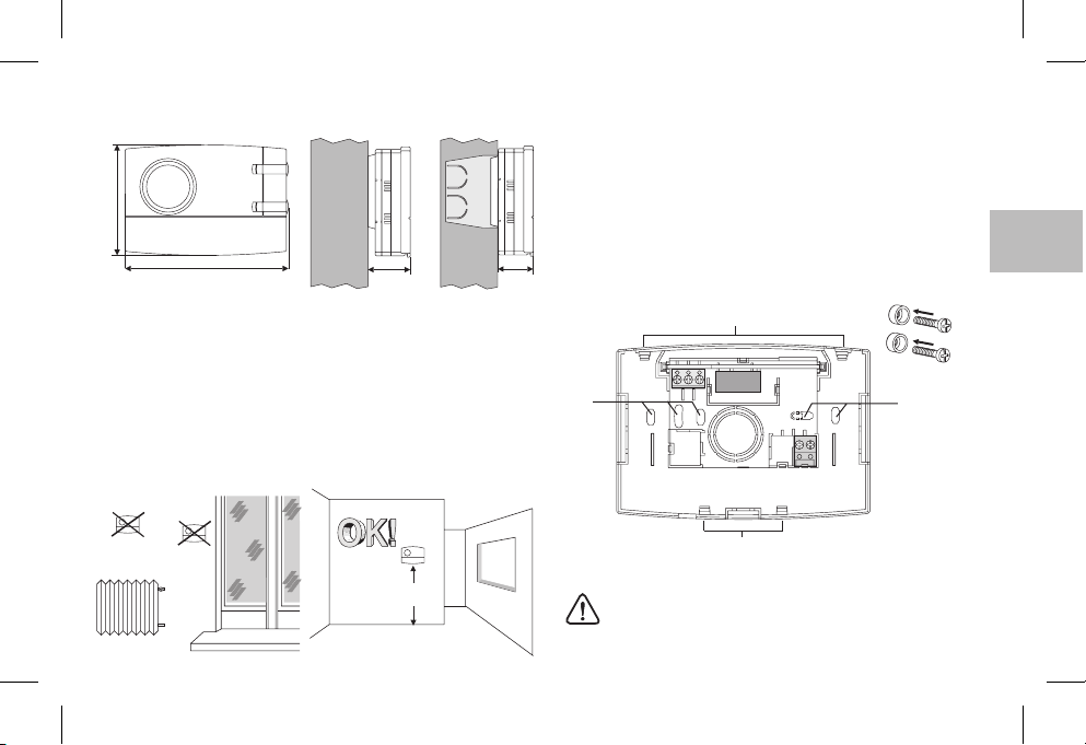
2 - OVERALL DIMENSIONS
82
4 - ATTACHING THE BASE TO THE WALL
Switch off mainspower to device
Using screws, attach thebase to the wall,to the round or rectangular
built-in boxusing theappropriate pairs ofholes .A
If the wallwhere thebase of thechronothermostat is tobe attached is
metal, insertthe insulating washersinto thetwo screws.
121,5
31,5 26
3 - INSTALLATION GUIDELINES
Chronothermostat installation: independent-fixed
Wall mounting - in round box - semi-recessed in rectangular box
of 3 modules.
Install the device approximately 1.5 m off the ground well away
from sources of heat, windows and anything else that can affect
its normal stateof operation.
!
h 1,5 m
A - attachment holes
B - wire passage from round, rectangular box
C - chronothermostat attachment teeth
C
3
A A
21
4
5
6789
B
C
To ensure the chronothermostat is correctly fitted to the
base on thewall, it must not in any waybe buckled due to
over tightening the screws fixing to the rectangular or
round box builtinto the wall.
EN
15
Page 16
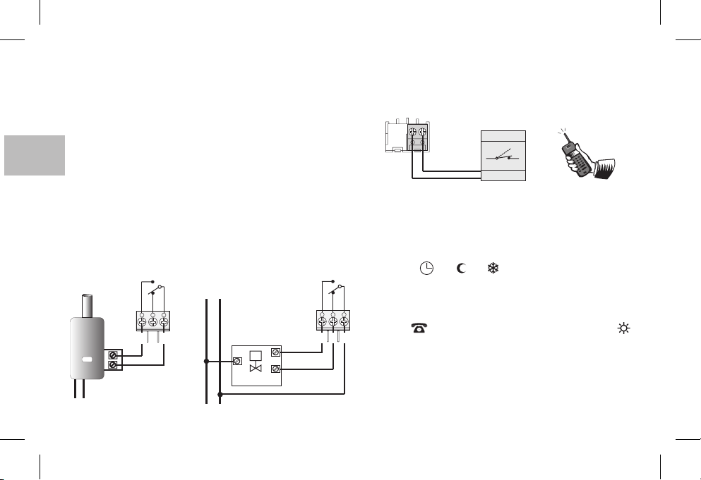
5 - ELECTRICAL CONNECTIONS
Important: Installation and electrical connections of devices and ap-
pliances must be carried out by skilled people and in compliance
with current regulations. The manufacturer declines all responsibility for the use of products that must conform to specific environmental and/or installation standards.
Note for the installer: If surface mounting (e.g. on awall), have suitable raceways forthe cables incompliance withcurrent standards.
Check thatthe relayload doesnot exceedthe figure given in the tech-
G
F
EN
nical data.
B
Switch off mains power to the device.
Connect the device to be controlled to the terminals:
1-common
2-3-normally closed contact
normally open contact
Examples of electrical connections
230V~
N
L
Connection to a
motorized valve
M
LOAD
OPEN
CLOSE
Connection to a water heater
WATER
WATER
HEATER
HEATER
L
N
230V~
16
NO
C
NC
231
Connecting a phone programmer for remote control
The terminals and of the chronothermostat are fitted for
connecting a phone programmer with a normally open contact.
89
6789
e.g.
Telephone programmer
Contact
Functioning with the telephone programmer
The phone programmer governs the chronothermostat closing
the contact connected to terminals and .89
To turn on the chronothermostat with the phone programmer you
need toset the switchonto one of thefollowing typesof operation:
AUTOMATIC or or .
NO
When the programmer is turned on (contact onterminals 8 and 9
C
closed) the chronothermostat passes from one of the conditions
NC
set with
the switch to always on comfort temperature
t
t
operation: besidesshowing all 48 indiceson, thedisplay will show
the symbol for the phoneprogrammerturned onand the
231
Comfort symbol blinking.
Turningoff forcingwith thephone programmer
Open the phone programmer contact (see programmer
instructions) showing thechronothermostat in thecurrent mode of
operation at thetime of switchingon.
Note: The onand off controls areoperative within1 minute.
Page 17
6 - ATTACHING OR REMOVING THE CHRONOTHERMOSTAT FROM THE BASE
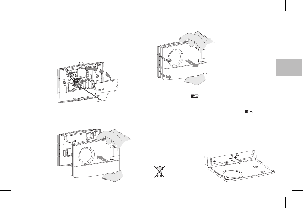
Fit the cable cover on by inserting the tooth into the slot in
the base, thensecure it bylightly pressing onthe hooks
Use asmall screwdriver to removethe coverby leveringon each
hook in succession
F.
F
D E
F.
To remove the chronothermostat
from the base on the wall, grip it
as shown in the figure, then
extract it by turning it on the righthand side.
EN
E
D
Hook the chronothermostat ontothe base, taking care toinsert
the contacts correctly, thenexert light pressure untilyou hearthe
click of theattachment teeth.
7- FITTING/REPLACING THE BATTERIES
When the symbol appears, this indicates that the
batteriesare runningout. Fromthis moment,there are30 days
to change them.
the indicatedtime, the display will turnoff and the symbol will
remain constantly lit.
All thermoregulation operations are suspended and all settingsare
saved to berestored when thenew batteries areinserted.
Replace the dead batteries with two 1.5 V AA
batteries (LR6)
CAUTION.: when changing batteries, the time available to
perform the operation without losing data
is about 1 minute
flashing
If the almost flat batteries are not replaced within
paying attention to their polarity.
Dispose of flat
batteries in the
proper containers.
alkaline Penlight
17
Page 18
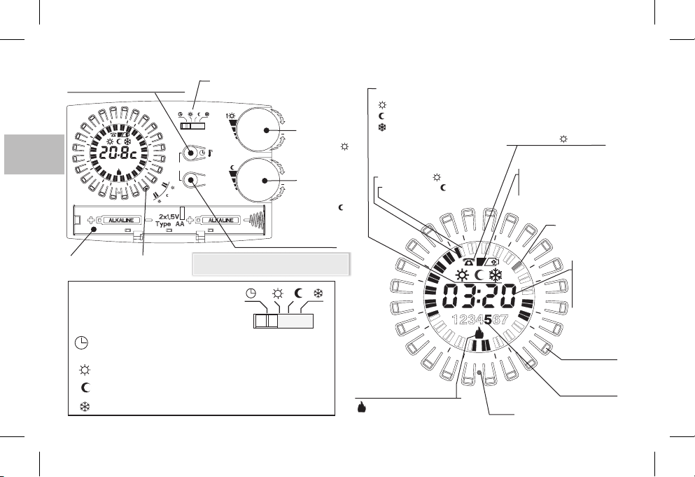
8 - GENERAL VIEW, DISPLAY LEGEND AND KEY FUNCTIONS
Settings button: hours-minutes
or Room temperature display
4
2
G
F
B
EN
Battery
housing
21
8
1
15
1234567
2
1
R
3
9
Key
“tappet”
6
TYPE OF OPERATION
t
t
t
Switch - operation mode type
(see details in box below)
t
t
t
/
copy
t
Day
Note: more particular button functions are
described inthe specificparagraphs.
+
+
Day selector button
(weekly model)
(5 ÷ 30 °C)
Comfort temp.
setting
adj. Knob
t
(5 ÷ 30 °C)
Economy temp.
(energy saving)
setting
adj.knob
t
ttt
Display of the type of
operation in progress:
Display of the current
program
Index ON = t comfort
THAT CAN BE SELECTED
WITH THE SWITCH
AUTOMATIC - Comfort or Economy adjustable from 5 to 30 °C;
Always ,Comfort adjustable from 5 to 30 °C (all 48 indices on)
t
Always ,Economy adjustable from 5 to 30 °C (all 48 indices off)
t
Always ,Antifreeze temperature fixed on 5 °C (all 48 indices off)
t
18
as per indices programming with the key (tappet)
Consumer status indicator
blinking = relay on
off = relay off
Comfort
Economy
Antifreeze
Index OFF = t economy
21
8
1
15
Turning on with the
phone programmer
(with blinking indicator)
Battery indicator:
- almost flat
- flat
4
2
3
9
1
2
R
Reset
(blinking)
(constantly lit)
Current 1/2h
index blinking
6
Key (tappet)
Day
(Weekly mode)
E.g. 5 = Friday
Current hour or
room temperature
detected
/ temperature
setting
Page 19
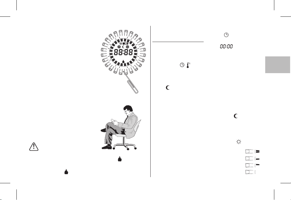
9 - RESET
When switching on for the first time
or if the chronothermostat shows anomalous displays or improper functioning,
etc., inserta thin rod(max 1mm) into the
hole onthe ringbetween thekey (tappet)
R
marked then press briefly. The display
will switch on all the segments for a few
seconds The display will show all segments fora few seconds, asshown inthe
diagram to the side, and alldata present
in the memory will be deleted, restoring
all default settings (except for settings
with microswitches).
The chronothermostat will be ready for programming again (see Chapter 10).
4
2
21
8
1
15
123 5674
3
6
9
1
2
R
Easy Programming
All the operations described in the
following paragraph can be carried out
before securing the chronothermostat
to the base on the wall; this allows you
to do the programming while being
comfortably seated.
CAUTION !
If the chronothermostatis programmed before beingattached to thebase on the
wall, once installationis complete the symbolon the display (off or blinking)
might not correspond to the actual state of the relay. Within of
attaching the chronothermostat to the base on the wall, the relay will turn on as
indicated onthe display (off or blinking).
max 1 minute
10 - PROGRAMMING
Set the switchon operation
IMPORTANT:do a RESET
After a few seconds, the device shows blinking, enter the
current hours andminutes as describedbelow.
Entering current hoursand minutes
Press button to program thehour:
- keeping itpressed adjuststhe hours;
- repeatedly pressingsets theminutes;
(on the daily model, wait for5 seconds forthe display toshow the
symbol and the ½ h index corresponding to the programmed
time blinking).
Entering current day
The display showsday correspondingto blinking.
Select the day of the current week with the button
(wait for5 secondsfor the displayto showthe symboland the
half hourindex corresponding tothe programmedtime blinking).
Programming comforttemperature atdesired times
Press and release
display corresponding to the times for activating the comfort
temperature (temperature level set with knob ), proceeding
as follows:
press and releaseto activate theentire hour
1st
press andrelease toactivate the firsthalf hour
2nd
press and release to activate the second half hour
3rd
press andrelease todeactivate the entirehour
4th
AUTOMATIC .
/
(weekly model only)
1 Monday
Day
the key (tappet) arranged in a ring on the
t
EN
19
Page 20
Copying the programto otherdays (weekly modelonly)
After programming the day you can copy it onto the next
(copy)
day by and .
pressing simultaneously buttons Day
/
If you want to set other programs, choose the day with the
button then do the programming by pressing the key (tappet)
as described above.
Displaying programs entered relating to the days of the
G
F
EN
week (weekly modelonly)
B
Press and releasethe keyrepeatedly.Day
Note: When you finish programming or viewing, 5 seconds after last
pressing the button, the chronothermostat will automatically go into
the operatingstate (index ofthe current h blinking).½
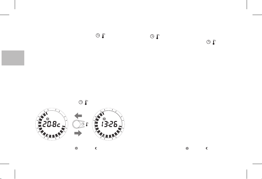
It is possible at any time to pass from viewing the display of the
current time to the ambient temperature (degrees centigrade) and
vice versa, bybriefly pressing the button.
4
2
21
1
8
1
15
Display Set temperaturet and/or t set
refer to paragraph11
20
3
6
3
9
2
1
1
/
4
2
21
8
1
/
3
15
2
21
1
CHANGING SETTINGS
Changing the currenttime
Keep button pressed until the current time blinks
Day
/
Change the hour and/or minutes with the button as
/
described above.
Changing the currentday
Keep the button pressed until the number corresponding
Day
(weekly model only)
to the current day blinks.
Set the new current day by pressing the button
Day
Changing the entered programs
Daily model
Change the program by using the key (tappet) as described
above
Weekly model
Change the program for the current day by using the key
(tappet) as describedabove
3
9
To changethe programfor theothers day of the week select the
desired day with the button and use theDay
6
described above
Note: when you finish making your changes, 5 seconds after last
pressing the buttons, the chronothermostat will automatically go
key (tappet) as
into theoperating state (indexof thecurrent blinking).½h
Modify T Settemperature t and/or t set
refer to paragraph11
Page 21
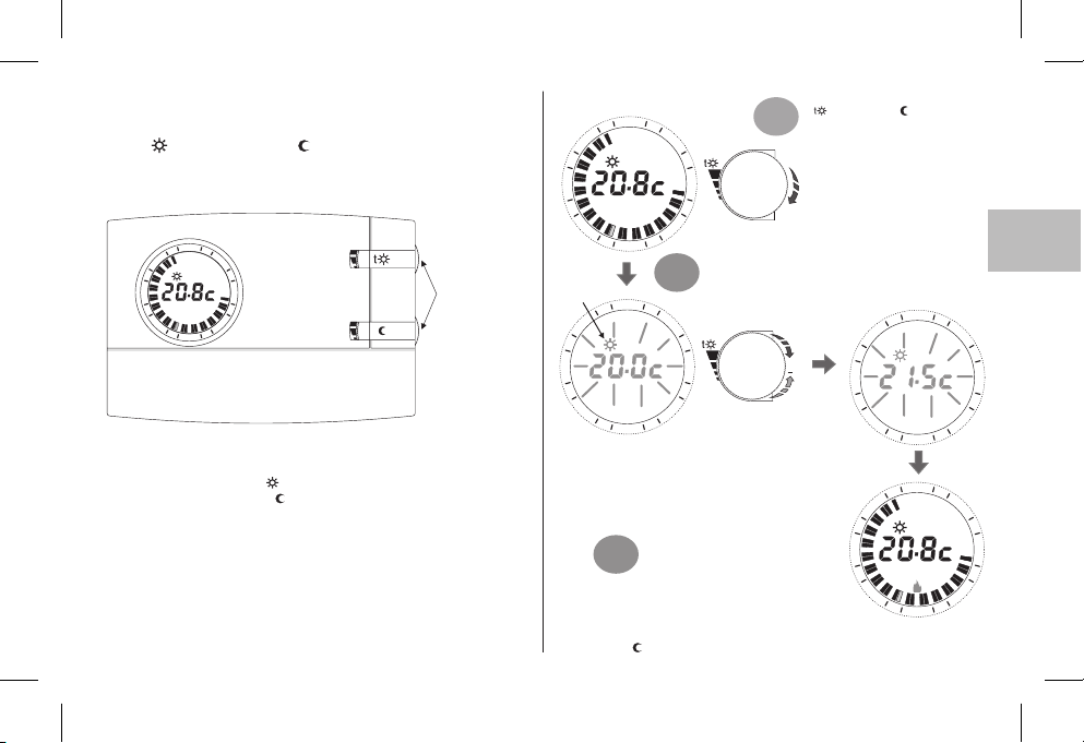
11 - DISPLAY/MODIFY SET
TEMPERATURES
(via knobs):
t COMFORT / t ECONOMY
The display normallyshows room temperaturedetected
or current hoursand minutes.
4
2
21
3
8
1
15
6
3
9
1
2
t
upon first start-up of the chronothermostat or after reset operation,
preset default temperaturesare:
Comfort TemperatureSet
Economy TemperatureSettt
=
20.0 °C /68.0 °F(upper knob)
=
17.0 °C /62.6 (lower knob)°F
In any chronothermostatoperating condition, to display the current
settings, simply slightly turn the relative knob until the set itself
blinks. After 5 sec., the display will return to normal operation
visualisation. If settings do not meet user needs, it is possible to
modify themas desiredat anytime, from+5°C to+30 °C(from +41
°F to +86°F), as perprocedure shown tothe side.
Knobs can be
turned without
opening the cover.
Slightly turn the desired knob
4
2
1
21
8
1
3
6
( comfort or economy) to
1°
view the current Set
temperature valuesand access
adjustment procedures.
t
3
15
Indicates setting
modification
21
8
1
15
Note: if a temperature limit was set (see following paragraph), the set value can be increased up to said limit
(blocked setting).
3°
Perform the same procedure to set the Seteconomy temperature
with knob t
9
1
1
2
4
2
1
2
The desiredSet starts toblink. Then, turn theknob
clockwise to increase or counter-clockwise to
decrease (a variation of 0.1°C/0.1 °F at a time will
2°
be obtained).
3
6
9
The temperatureset
will therebybe the new
reference Set.
After 5sec. fromthe last turn of the
knob, the display will return to
regular operatingconditions
4
2
21
+
8
1
15
1
2
4
2
1
21
8
1
3
15
1
1
2
EN
3
6
9
3
6
9
21
Page 22
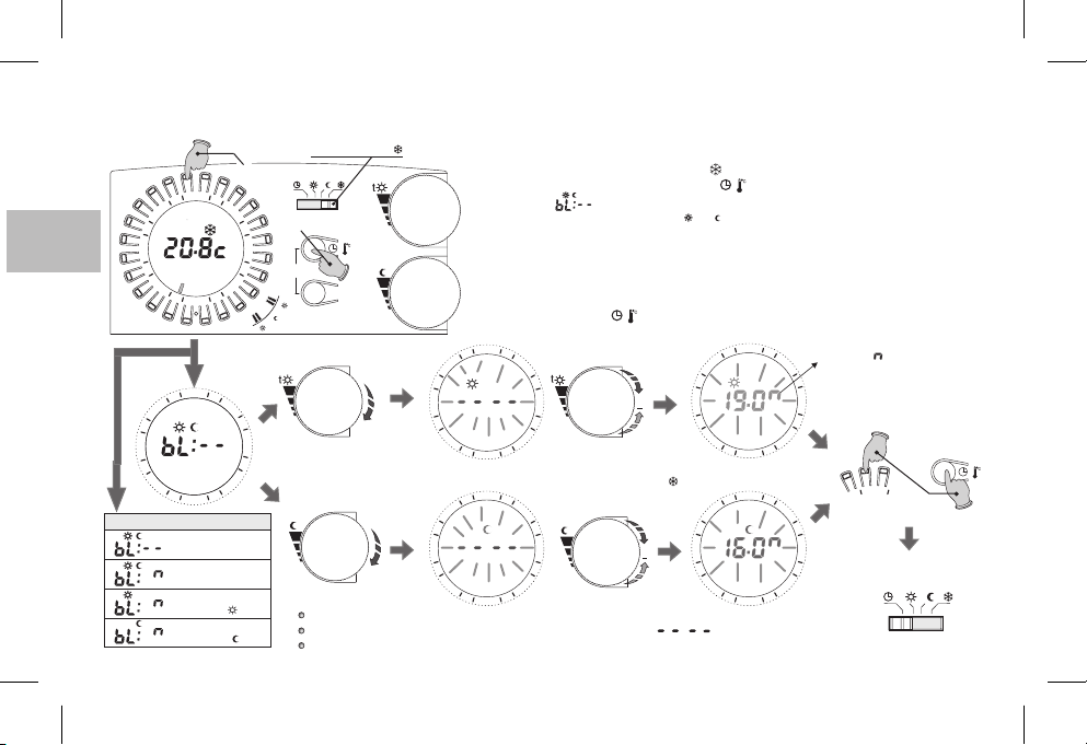
12 - COMFORT AND/OR ECONOMY TEMPERATURE MAX SET LIMIT (LOCKED SETTING)
In some particular installations, for instance in public offices, hotels, etc., it may be useful to lock the chronothermostat temperature settings to avoid incorrect settings being entered by
unauthorised personnel.
h23 button
G
F
B
EN
8
1
8
1
Possible displays
22
4
2
21
12 45673
15
2
1
R
4
2
21
15
1
2
No locked setting
(default setting)
Locked setting on
both sets
Locked setting only on
comfort set t
Locked setting only on
economy set t
Press together for 4s.
3
6
9
3
6
9
Move the switch to t
t
t
t
/
copy
t
t
t
and/or
Important: after 20 sec. without any knobs being turned, the device will automatically exit from locked
setting programming without saving any settings and willmove to anti-freeze(t ) operation
t
Notes:
The reset control will cancel any locked settings
t
Day
The basic setup does not contain any locked settings.
To cancel any previously locked settings, bring the Set/s to:
It will then be possibleto lock the maximumSet temperature values (comfort and/or economy) as
follows:
1
- Movethe switch toanti-freeze mode t (set fixedat +5°C,not adjustable)
2
- Press theh23 button on the ringand the button simultaneously for4 sec.; thedisplay
will show: (i.e. defaultsetting= no lock).
3
- Slightly turn the desiredset knob (t or t ) to view the current setting.
4
- The Setwill start to blink.After 3 sec., set theblock setting (limit) from+5,1°C to
+29,9°C, turning theknob clockwise to increaseor counter-clockwise to decrease(a varia-
tion of 0.1°Cat a time willbe obtained).
5
-Ifdesired,
6
7
4
2
21
8
1
15
2
1
4
2
21
8
1
15
2
1
repeat the operationsindicated in points 3and 4 with the otherhand piece.
- Within 20 sec., savethe setting/s and exit from programming, pressingthe h 23 buttonon
the ring andbutton simultaneously for 4sec.
- Bring theswitch back to thedesired operating mode.
3
6
9
3
t
6
9
/
+
+
/
4
2
21
8
1
15
2
1
4
2
21
8
1
15
2
1
This symbol indicates max locking
3
temperature, for both °C and °F ranges
6
9
3
9
and exit from programming
Press together for 4s
6
desired operating mode
To save setting/s
42
Bring the switch to
t
/
t
t
Page 23
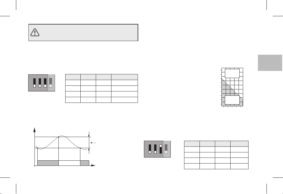
The settings of the microswitches (dip-switches)
on theback of the chronothermostat mustbe made
by qualified personnel.
13 - TEMPERATURE DIFFERENTIAL
The chronothermostat worksin ON-OFF differential mode(Dip
3 OFF) withthe default differentialsetting of (0,54°F)0,3°C .
The differential can be changed by moving the microswitches
(dip-switches) as shownin the table.
ON
ON
ON
1
1
The differentialmust beset according tothe system's thermal inertia;
a low settingis recommended for systemswith radiators (e.g. made
of castiron) anda highsetting forsystems with fan-coils.
°C
Measured temperature
ON
Dip 1 Dip 2 Dip 3
OFF OFF OFF
32
32
4
OFF ON OFF
OFF
OFF
ON OFF OFF
ON ON OFF
Adjustable differential
0,3 °C - 0,5 °C - 0,7 °C - 0,9 °C
(0,54 °F - 0,9 °F - 1,26 °F - 1.62 °F)
OffOn On
Time
Differential
0,3 °C (0,54 °F)
0,5 °C (0,9 °F)
0,7 °C (1,26 °F)
0,9 °C (1,62 °F)
14 - PROPORTIONAL OPERATION
As an alternative to the differential, it is possible to adjust the
temperature proportionally (Dip 3 ON); this system enables
saving onenergy consumptionand alsoon the wear of the burner
by limiting the number of ignitions. The duration of each ignition
depends not only on the set cycle but also on the difference
between theset temperatureand themeasured temperature (see
example).
Example of setting t= 20°C - Cycle = 10min
t = 20,5 °C Consumer alwaysOFF
t = 20,4 °C Consumer 1min ON- 9min OFF
t = 20,3 °C Consumer 2min ON- 8min OFF
t = 20,2 °C Consumer 3min ON- 7min OFF
t = 20,1 °C Consumer 4min ON- 6min OFF
t = 20,0 °C Consumer 5min ON- 5min OFF
t = 19,9 °C Consumer 6min ON- 4min OFF
t = 19,8 °C Consumer 7min ON- 3min OFF
t = 19,7 °C Consumer 8min ON- 2min OFF
t = 19,6 °C Consumer 9min ON- 1min OFF
t = 19,5 °C Consumer alwaysON
The duration of the cycle is determined by the position of the
microswitches (dip-switches) on the back ofthe chronothermostat,
as shown in the table. A long cycle is recommended for systems
with high thermal inertia (cast-iron radiators, floor systems) and a
short cycle forsystems with lowthermal inertia (fan-coils).
ON
1
ON
Dip 1 Dip 2 Dip 3
OFF OFF ON
4
32
OFF ON ON
OFF
ON OFF ON
ON ON ON
°C
20,8
Consumer
OFF
20,6
20,4
20,2
20,0
19,8
19,6
Consumer
19,4
ON
19,2
01024 6 8 Minutes
Duration Cycle
7 min
10 min
15 min
20 min
ENEN
23
Page 24
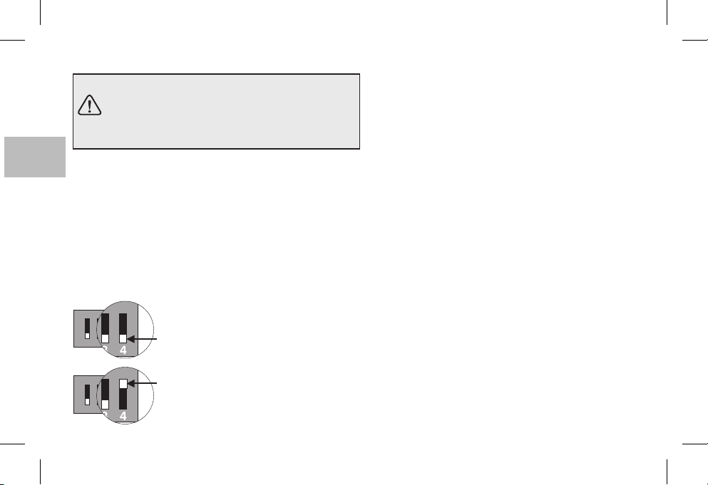
15 - TEMPERATURE SCALE °C or °F 16 - WARNINGS
ATTENTION:
the chronothermostat is preset to operate in
Celsius degrees and can be modified by the
installer or an expert user to function in
Fahrenheit degrees (°F).
G
F
Microswitch on the back of the chronothermostat is default
EN
B
set to the position(Celsius degrees).
It can bemoved tothe position:the display,afterperforming
4
OFF
ON
a RESET operation, will show room and Set temperature in
Fahrenheitdegrees (°F).
To return to Celsius display, bring microswitch to the
4 OFF
position and performa RESET operation.
In both cases, reprogramme the chronothermostat as
indicated in chapter10).
ON
OFF = Celsius degrees (°c) range
432
1
ON
432
1
24
(default setting)
ON = Fahrenheit degrees (°F) range
Please read this instruction booklet carefully and keep it for
future reference.
The figures shown in the manual depict the display with
settings in C°(Celsius degrees).
If the display shows an ambient temperature of
50,0 °C the measured temperature
is off thescale.
Use only1,5V AAalkaline batteriesLR6 (notincluded inthe
package ), using inappropriate batteries may cause the
entered programming tobe lost.
N.B.: The product has been tested and it ensures its
characteristics with DURACELL or ENERGIZER alkaline
batteries.
Important:
it is recommended to replace them at least every 24
months toavoid them discharging whenyou areaway (e.g.
Christmas holidays, etc.)
If necessary, clean the chronothermostat with
a slightly moistcloth.
The manufacturer reserves the right to make all technical
and manufacturing modifications deemed necessary
without prior notice.
blinking, it means that
00.0 °C or
battery lifemay bemore than 2 years. However,
Page 25

1 - DONNÉES TECHNIQUES
Tension d'alimentation :
Autonomie :
Autonomie après l'affichage du symbole piles
déchargées :
Type d'action, déconnexion et appareil :
Logiciel :
Tension impulsive nominale :
Type de sortie :
Section des fils aux bornes de relais :
Entrée pour programmateur téléphonique :
Section des fils aux bornes du programmateur téléphonique :
Type d'isolation :
Degré de protection :
N.bre d'index programmables sur la couronne de l'horloge :
Temps minimum programmable à l'aide des touches cavalier :
Pollution :
Échelle de réglage de la température à l'aide du bouton :
t
- Confort:
t
- Réduite (économie) :
Limitation de la température (blocage paramètre t max.) :
Température antigel fixe ( ):
Précision de réglage de la température :
Échelle d'affichage de la température ambiante :
Tolérance de lecture de la température ambiante :
Limites de la température de fonctionnement :
Limites de la température de stockage :
Gradient thermique :
Type de réglage de la température :
Précision de l'horloge :
Normes de référence pour le marquage CE :
t
n° 2 piles alcalines rondes de 1,5 V type AA LR6
2 ans
1 mois
1 / BU / Électronique
classe A
4kV
à relais avec contact à fermeture / commun / à ouverture
libre de potentiel - max 5(3)A / 250 Vca
0,75 ÷ 2,5 mm
par contact à fermeture libre de potentiel
0,5 ÷ 1,5 mm
classe II
IP 30
48
½ heure
Normale
+5 ÷ +30 °C (default +20 °C) / +41 ÷ +86 °F (default +68 °F)
+5 ÷ +30 °C (default +17 °C) / +41 ÷ +86 °F (default +62,6 °F)
Step 0,1°C / 0 ,1 °F
+5 °C / 41 °F (fixe non réglable)
± 0,1 °C / ± 0,1 °F
0 ÷ +50 °C / +32 ÷ +122 °F
± 0,5 °C / ± 0,9 °F
0 ÷ +50 °C / +32 ÷ +122 °F
-20 ÷ +65 °C / -4 ÷ +149 °F
max 1K / 15 min.
fonctionnement Marche-Arrêt avec différentiel réglable à 0,3 - 0,5 - 0,7 - 0,9 °C
fonctionnement proportionnel avec cycles de durée réglable sur 7-10-15-20 minutes
± 1 s/jour
LVD et EMC EN60730-2-7 EN60730-2-9
2
2
(piles DURACELL ou ENERGIZER conseillées)
FR
25
Page 26
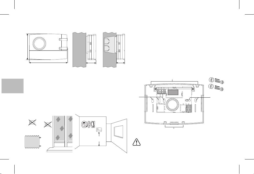
2 - DIMENSIONS HORS-TOUT
82
121,5
31,5 26
3 - NORMES D'INSTALLATION
D
FR
Installation du chronothermostat: indépendant-fixe
En saillie- sur boîte ronde -semi-encastré surboîte rectangulaire
3 modules.
Installer le dispositif à environ 1,5 m du sol, loin de sources de
chaleur,de fenêtres et detout cequi pourrait altérer lesconditions
de fonctionnement.
4 - FIXATION DE LA BASE POUR POSE EN SAILLIE
Couper l’alimentationsecteur de dispositifà commander
Fixer la base avec les vis: au mur, à la boîte à encastrer ronde ou
rectangulaire enutilisant les couplesde trouscorrespondants A.
Si la base du chronothermostat doit être posée sur un mur
métallique, placerdes rondelles isolantessur lesdeux vis.
A - trous de fixation
B - passage des fils provenant de la boîte ronde ou
rectangulaire
C - dents de fixation du chronothermostat
C
3
A A
21
4
5
6789
B
!
h 1,5 m
26
Pour monter correctement le chronothermostat sur la
base en saillie, celle-ci ne doit pas avoir été déformée à
cause d'un serrage excessif des visde fixation àla boîte
rectangulaire ou rondeencastrée dans lemur.
C
Page 27
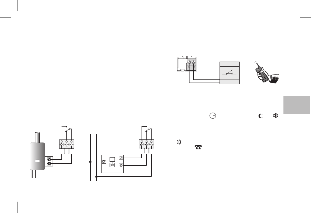
5 - BRANCHEMENTS ÉLECTRIQUES
Important :
des appareils doivent êtreeffectués par du personnel qualifié, conformément aux normes et aux réglementations en vigueur. Le fabricant
décline toute responsabilité en ce qui concerne les produits devant
respecter des normes particulières d'installation et/ou de protection
de l'environnement.
Note pour l'installateur :
mur), prévoir des canalisations conformes aux normes pour le passage
des câbles. Vérifier que la charge du relais ne dépasse pas la valeur indiquée dansles donnéestechniques.
Exemples de branchements électriques
Raccordement à une chaudière
CHAUDIÈRE
N
230V~
l'installation etle branchementélectrique desdispositifs et
en cas de montage en saillie (par ex. sur un
Couper l'alimentation secteur du dispositif à commander.
Raccorder le dispositif à commander aux bornes :
1-commune
2-3-contact normalement fermé
contact normalement ouvert
Raccordement à
NO
C
NF
230V~
N
L
vanne motorisée
231
CHARGE
L
une
OUVERTURE
M
FERMETURE
NO
NF
231
Raccordement d'un programmateur téléphonique
pour commande à distance
Les bornes et du chronothermostat permettent deraccorder
un programmateur téléphonique doté d'un contact à fermeture.
89
6789
télécommande téléphonique
Ex.
Contact
Fonctionnement avec programmateur téléphonique
Le programmateur téléphonique commande lechronothermostat
en fermant le contact relié aux bornes et .89
Pour activer le chronothermostat à l'aide du programmateur
téléphonique, il faut mettre le commutateur sur l'un des modes de
fonctionnement suivants : AUTOMATIQUE ou ou .
Quand le programmateur est activé (contact aux bornes 8 et 9
fermé), le chronothermostat passe de l'une des conditions
C
sélectionnées avecle commutateur
de confort
: en plus des 48 index allumés, l'écran affiche le
toujours surla température
t
symbole indiquant que le programmateur téléphonique est
activé et lesymbole clignotant de latempérature de confort.
Désactivation dela commandepar le programmateurtéléphonique
Ouvrir le contact du programmateur téléphonique (voir notice du
programmateur) demanière à ramener lechronothermostat dansle
mode defonctionnement où il setrouvait aumoment de l'activation.
Remarque: les commandes d'activation et de désactivation entrent en
fonction dansun délaide 1 minute.
FR
t
27
Page 28
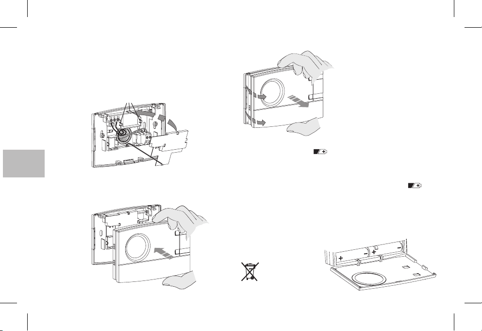
6 - FIXATION OU RETRAIT DU CHRONOTHERMOSTAT DE LA BASE
Appliquer le cache sur les câbles en insérant la dent dans
l'encoche de la base, puisle fixer en exerçant une légère pres-
E
sion dans lescrochets
Pour ôter le cache, utiliser un petit tournevis en faisant levier sur
chaque crochet .
F.
F
F
D
Pour retirer le chronothermostat
de la base en saillie, le saisir
comme le montre la figure, puis
l'extraire enle faisantpivoter vers
la droite.
E
D
FR
Accrocher le chronothermostat à la base en veillant à introduire
correctement les contacts, puis exercer une légère pression
jusqu'à entendre ledéclic des dentsde fixation.
28
D
7- MISE EN PLACE OU REMPLACEMENT DES PILES
L'apparition du symbole indique que les piles sont
presque épuisées ; il vous reste alors 30 jours pour effectuer leur
remplacement.
Si les piles presque vides ne sont pas remplacées dans le temps
indiqué, l'écran s'éteindraaffichant uniquement lesymbole fixe.
Chaque activité de thermorégulation est suspendue et tous les
paramètres sont enregistrés pour être restaurés lors de l'installation
des nouvelles piles.
Remplacer les piles usées par deux rondes de 1,5
V, type AA (LR6)
ATTENTION : le temps à disposition pour le remplacement des
piles sans perdre les données
est d'environ 1 minute.
en faisant attention à la polarité.
Jeter les piles usées
dans un conteneur
prévu àcet usage.
clignotant
piles alcalines
Page 29
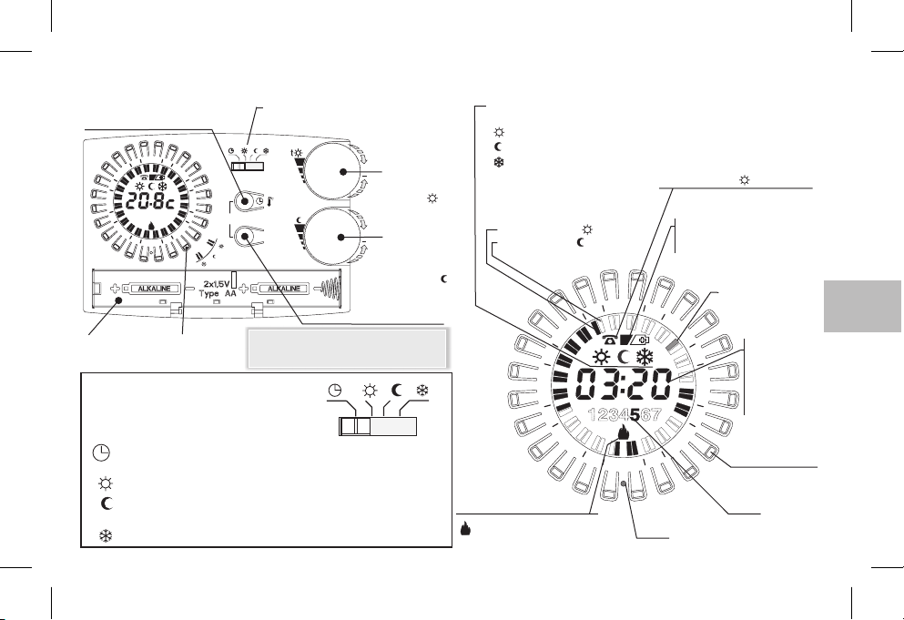
8 - VUE GÉNÉRALE LÉGENDE DES INDICATIONS AFFICHÉES ET FONCTIONS DES TOUCHES
Bouton de paramétrage :
heures-minutes ou visuel.
Température ambiante
4
2
8
1
15
Logement
des piles
21
1234567
2
1
R
3
9
Touche
“cavalier”
6
t
Commutateur (voir les détails dans le
t
t
t
/
copy
Day
t
t
Nota: d'autres fonctions particulières des
touches sont décrites dans les paragraphes
spécifiques d'utilisation.
TYPE DE FONCTIONNEMENT
SÉLECTIONNABLE À L'AIDE
t
cadre ci-dessous)
(5 ÷ 30 °C)
Bouton rotatif
de régl. des
+
températures
des Paramètres
confort
t
(5 ÷ 30 °C)
Bouton rotatif
+
de régl. des
températures
des Paramètres
réduction
(Économie)
Touche de sélection du jour
(mode hebdomadaire)
ttt
Affichage du type de
fonctionnement en cours :
Affichage du programme
sélectionné
Index allumé = t Confort
Index éteint = t Réduction
t
Confort
Réduction
Antigel
1
Activation à l'aide du
programmateur téléphonique
(avec indicateur clignotant)
Indicateur des piles :
- presque déchargées
- déchargées
Index ½ heure
4
2
21
8
courante clignotant
3
6
(clignotant)
(fixe)
Heure courante
ou température
ambiante relevée /
affichage
température
en réglage
DU COMMUTATEUR
AUTOMATIQUE - Confort ou Température réduite réglable de5à30°C;
Toujours, Confort réglable de5à30°C(les 48 index sont tous allumés)
t
Toujours, Température réduite réglable de5à30°C
t
Toujours, température fixeà5°C(les 48 index sont tous éteints)Antigel
t
selon la programmation des index avec les touches cavalier
(les 48 index sont tous éteints)
15
Indicateur d'état du récepteur
clignotant = relais activé
éteint = relais désactivé
1
R
9
2
Reset
Touche “cavalier”
Jour
(mod. Hebdomadaire)
ex. 5 = vendredi
FR
29
Page 30
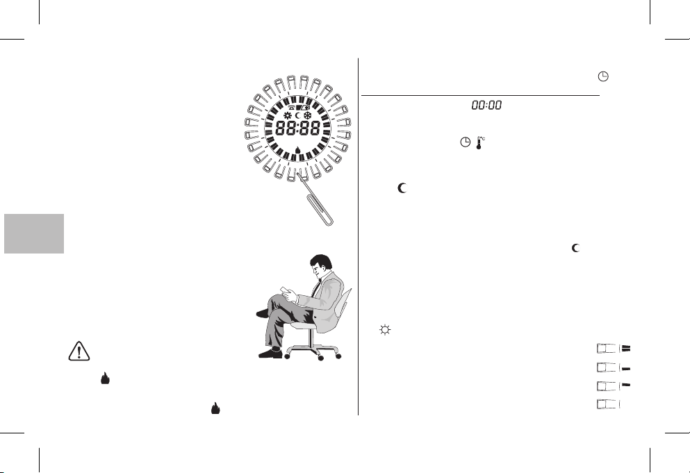
9 - RÉINITIALISATION
À la première mise sous tensionRou en
cas d'anomalies au niveau de l'affichage ou
du fonctionnement du chronothermostat
21
etc., introduire une pointefine (1 mmde diamètre maxi) dans le trou repéré par la lettre
, situé sur la couronne entre les touches
cavalier, puis appuyer brièvement. L'écran
allumera tous les segments pendant
8
1
123 6745123 674
15
quelques secondes comme sur la figure cicontre et toutes les données présentes
dans la mémoire seront supprimées, restaurant les paramètres d'usine (sauf les
paramètres avecles micro-interrupteurs).
D
Le chronothermostat est alors prêt pour une nouvelle programmation
FR
(voir Chapitre 10).
Programmation facilitée
Toutes les opérations décrites dans ce
paragraphe peuvent être effectuées avant de
fixer le chronothermostat àla base pour pose
en saillie ; il est donc possible d'effectuer la
programmation confortablement assis dans
son fauteuil.
ATTENTION !
Si le chronothermostat a été programmé avant sa fixation à la base en saillie, le
symbole (éteint ou clignotant) affiché à l'écran une fois l'installation terminée
pourrait ne pas correspondre à l'état réel du relais. Dans un délai
après la fixation du chronothermostat à la base pour pose en saillie, le
minute
relais s'activeraselon l'indication affichée (éteinte ouclignotante).
30
4
2
1
2
R
maxi de 1
10 - PROGRAMMATION
Mettre le commutateursur fonctionnement .
IMPORTANT:RÉINITIALISER le chronothermostat.
3
Après quelquessecondes, clignote à l'écran.Entrer l'heure
et les minutesactuelles en procédantcomme décritci-après.
6
Entrée de l'heureet des minutesactuelles
9
Appuyer sur latouche pour réglerl'heure:
- en maintenantla touche enfoncée,on règleles heures;
- en appuyantpar impulsions, onrègle lesminutes ;
(sur le modèle journalier, attendre 5 secondes pour l'affichage du
symbole et de l'index de la demi-heureclignotant correspondant
à l'heure programmée).
Entrée du jouractuel
L'écran affiche lejour clignotant correspondantau
Sélectionner le jour de la semaine à l'aide de la touche
(attendre 5 secondes pour l'affichage du symbole et de l'index
de lademi-heure clignotant correspondantà l'heureprogrammée).
Programmation de la température de confort aux
horaires souhaités
Appuyer et relâcher
sur l'écran et correspondant aux heures auxquelles activer la
température de confort (température réglée à l'aide du bouton
), procéderde lamanière suivante:
t
1ère pression et relâchement pour activer l'heure
2ème pression et relâchement pour activer la première demi-heure
3ème pression et relâchement pour activer la seconde demi-heure
4ème pression et relâchement pour désactiver l'heure
/
(seulement pour lemodèle hebdomadaire)
1 Lundi.
les touches cavalier disposées en couronne
AUTOMATIQUE
Day
Page 31
Copie du programme sur plusieurs jours (seulement
pour modèle hebdomadaire)
Après avoir programmé le jour, il est possible de le copier
sur le joursuivant en
Day
/
Pour utiliser des programmes différents, choisir le jour
à l'aide de la touche puis effectuer la programmation en
appuyant sur lestouches comme décritci-avant.
Affichage desprogrammes relatifsaux joursde la semaine
(seulement pour modèlehebdomadaire)
Appuyer et relâchertour à tourla touche .Day
appuyant simultanément surles touches
.
Day
(copy)
Remarque :une foisla programmationou lavisualisation terminée,5
secondes après la dernière pression d'une touche, le chronothermostat passeautomatiquement en mode opérationnel (indexde la
heure couranteclignotant).
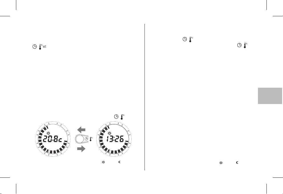
Il est possible de basculer à tout moment de l'affichage de l'heure
courante à celui de la température ambiante (degrés centigrades)
et vice versa,en appuyant brièvementsur la touche .
4
2
21
1
8
1
15
Affichage Paramètre detempérature t et/ou t configuré
Voirparagraphe 11
3
6
8
1
/
3
9
2
1
1
/
4
2
21
15
3
6
3
9
2
21
1
MODIFICATIONDES RÉGLAGES
Modification de l'heureactuelle
Appuyer sur la touche jusqu'au clignotement de l'heure courante
Modifier l'heure et/ou les minutes à l'aide de la touche
comme décrit ci-avant.
Modification du jour actuel
Appuyer sur la touche jusqu'au clignotement du numéro
/
(seulement pour modèle hebdomadaire)
Day
correspondant au jour en cours.
Changer le jour en appuyant sur la touche .
Day
Modification de programmes
Modèle journalier
Modifier le programme en utilisant directement les touches
½
cavalier comme décritci-avant.
Modèle hebdomadaire
Modifier en intervenant
le programme du jour courant
directement sur lestouches cavalier commedécrit ci-avant
Pour modifier les programmes des autres jours de la semaine
sélectionner le jour souhaité à l’aide de la touche , puis
entrer les nouveaux paramètres directement avec les touches
cavalier
comme décrit ci-avant.
Remarque : unefois la modification terminée,5 secondes après
la dernière pression d'une touche, le chronothermostat passe
automatiquement en mode opérationnel (index de la 1/2 heure
courante clignotant).
Modification Paramètre de température t et/ou t configuré
Voir paragraphe 11
/
FR
Day
31
Page 32
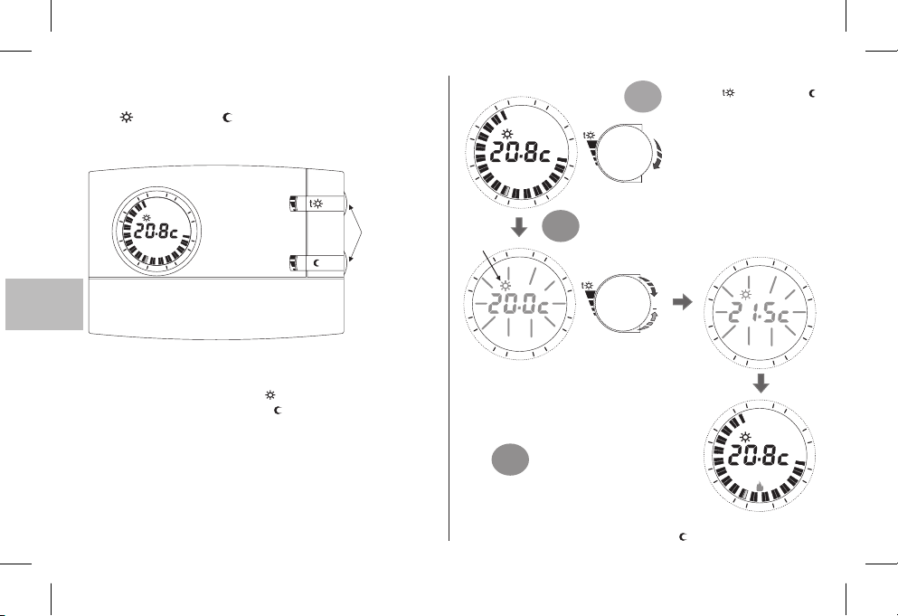
11 -
AFFICHAGE/MODIFICATION DES TEMPÉRATURES
DU PARAMÈTRE
(à l'aide du bouton rotatif):
t CONFORT / t RÉDUCTION
En règle générale, l'écran affiche la température ambiante relevée
ou les heureset minutes courantes.
4
2
21
3
8
1
15
D
FR
À la première mise sous tension du chronothermostat, ou bien
après la commande de reset, les Paramètres de température
préfixés en usinesont :
Paramètre de Température de confort
Paramètre de Température de réductiontt
Pour afficher les paramètres courants quel que soit l'état
opérationnel dans lequel se trouve le chronothermostat, il suffit de
tourner légèrement le bouton concerné jusqu'au clignotement de
ce paramètre, après 5 sec. l'écran revient à l'affichage de
fonctionnement normal. Si les paramètres configurés ne vous
satisfont pas, ils peuvent être modifiés à volonté à tout moment de
+5°C à +30°C(de +41°F à +86°C), comme l'indique laprocédure
ci-contre.
6
3
9
1
2
t
20.0 °C / 68.0 °F (bouton supérieur)
=
17.0 °C / 62.6 (bouton inférieur)°F
=
32
Possibilité de tourner
le bouton sans ouvrir
le couvercle.
Tourner légèrement le bouton
4
2
1
21
8
1
3
6
souhaité ( confort ou
1°
réduction) pour afficher les
valeurs de température de
Paramètres courants et entrer
dans laprocédure deréglage.
3
15
Indication du
paramètre en cours
de modification
21
8
1
15
Note : si une limite de température a été configurée (voir
paragraphe suivant), la valeur du paramètre peut être
augmentée jusqu'àcette limite (blocage).
3°
Exécuter la même procédure pour configurer le Paramètre de
température de réductionavec le bouton t
9
1
1
2
4
2
1
2
Le Paramètre désiré se met à clignoter ; il suffit
ensuite de tourner le bouton dans le sens des
aiguilles d’une montre pour augmenter, et
2°
inversement pour diminuer (pendant larotation, la
variation sefera de0,1°C/0,1°F à lafois).
3
6
9
La température ainsi
choisie sera le nouveau
réglage deréférence.
5 sec. après la dernière étape de
rotation du bouton, l'écran revient
aux conditions de fonctionnement
normal.
4
2
21
+
8
1
15
1
2
4
2
1
21
8
1
3
15
1
1
2
t
3
6
9
3
6
9
Page 33
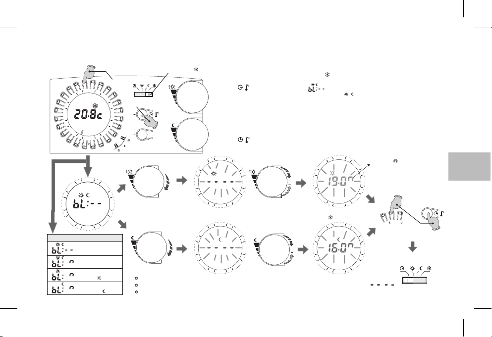
12 - LIMITE (BLOCAGE) DU RÉGLAGE MAX DE TEMPÉRATURE CONFORT ET/OU RÉDUCTION
Dans certains cas particuliers d'installation du chronothermostat, comme par exempleles édifices publics, les hôtels, etc., il pourrait être utile de limiter les paramètres de température max,
pour éviter des paramètres erronés effectués par du personnel non autorisé.
Touche 23h
4
2
21
8
1
12 45673
15
2
1
R
4
2
21
8
1
15
1
2
Affichages possibles
Aucun blocage
(paramètres d'usine)
Blocage sur les
deux paramètres
Blocage uniquement sur le
paramètres t confor t
Blocage uniquement sur
le paramètres t réduction
3
9
3
9
Déplacer le commutateur sur t
Appuyer sur les deux
boutons pendant 4s.
t
t
t
6
t
t
6
et/ou
/
copy
t
Important : après 20 sec. sans tourner undes boutons, le dispositif sort automatiquement de la programmation
des blocages sans enregistrer aucune configuration et semet en fonctionnementantigel (t )
t
Day
t
Note :
aucun blocage n'est configuré dans la configuration de base.
pour annuler d'éventuels blocages précédemment configurés, remettre le/les paramètre(s) sur :
la commande de reset annule les éventuels blocages configurés
Vous pourrezdonc limiter les valeursde Réglages (confort et/ou réduction) detempérature max comme suit:
1
- Déplacerle commutateuren mode antigelt (réglage fixeà +5°Cnon modifiable)
2
- Appuyersimultanément pendant4 sec. la touchesur la couronne correspondantà 23h et latou-
/
che l'écranaffichera :(par ex. paramètres d'usine -aucun blocage).
3
- Tournerlégèrement lebouton duparamètre désiré(t t ) pourvisualiser leparamètre en cours.
4
- Le Paramètre commence à clignoter ; après 3 sec. configurer le blocage (limite) de +5,1°C à
+29,9°C entournant le bouton dansle sens aiguillesd’une montrepour augmenter, et inversement pourdiminuer (pendantla rotation, lavariation detempérature se faitde 0,1°Cà la fois).
5
- Sivous lesouhaitez, répéter lesopérations indiquéesdans les points3 et4 avec l'autrepoignée.
6
- Sous 20 sec., enregistrer le(s) paramètre(s) et sortir de la programmation, en appuyant
simultanément pendant 4 sec. surle bouton sur la couronnecorrespondant à 23h et la touche .
/
7
- Remettrele commutateursur la modalitéde fonctionnementsouhaitée.
4
4
2
21
8
1
15
21
8
1
15
3
6
9
2
1
4
2
3
t
6
9
2
1
+
+
2
21
8
1
15
2
1
4
2
21
8
1
15
2
1
Le symbole indique la température
3
max limitable, aussi bien pour
l'échelle en °C qu'en °F.
6
Pour enregistrer le(s) paramètre(s)
9
3
9
et sortir de la programmation
Appuyer simultanément
6
Remettre le commutateur sur la modalité
de fonctionnement souhaitée
42
pendant 4 secondes
t
t
/
t
FR
33
Page 34
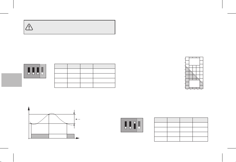
La programmation des commutateurs Dip (Dipswitch) situés au dos du chronothermostat doit
être confiée àdu personnel qualifié.
13 - DIFFÉRENTIEL DE TEMPÉRATURE
Le chronothermostat fonctionne en mode différentiel ON-OFF
(Dip 3 sur OFF) avec valeur du différentiel préréglée en usine
sur (0,54 °F).0,3 °C
La valeur du différentiel peut être modifiée en déplaçant les
commutateurs Dip (Dip-switch),comme indiqué dansle tableau.
ON
ON
ON
1
1
D
FR
La valeur du différentiel doit être réglée en fonction de l'inertie
thermique de l'installation ; il est conseillé d'utiliser une valeur
basse pour les installations avecdes radiateurs (parex. en fonte)
et une valeurélevée pour lesinstallations avec ventilo-convecteur.
°C
Température mesurée
34
ON
Dip 1 Dip 2 Dip 3
OFF OFF OFF
32
32
4
OFF ON OFF
OFF
OFF
ON OFF OFF
ON ON OFF
Différentiel réglable
0,3 °C - 0,5 °C - 0,7 °C - 0,9 °C
(0,54 °F - 0,9 °F - 1,26 °F - 1.62 °F)
OffOn On
Temps
Différentiel
0,3 °C (0,54 °F)
0,5 °C (0,9 °F)
0,7 °C (1,26 °F)
0,9 °C (1,62 °F)
14 - FONCTIONNEMENT PROPORTIONNEL
Au lieu du mode différentiel, il est possible de régler la
température en mode proportionnel (Dip 3 sur ON) ; ce système
permet des économies d'énergie et réduit l'usure du brûleur en
limitant sa durée de fonctionnement. La durée de chaque
allumage dépend non seulement du cycle programmé, mais
encore de la différence entre la température de consigne et la
température mesurée (voirexemple).
Exemple de programmation t= 20°C - Cycle= 10min
t = 20,5 °C Récepteur toujourséteint
t = 20,4 °C Récepteur 1min ON- 9min OFF
t = 20,3 °C Récepteur 2min ON- 8min OFF
t = 20,2 °C Récepteur 3min ON- 7min OFF
t = 20,1 °C Récepteur 4min ON- 6min OFF
t = 20,0 °C Récepteur 5min ON- 5min OFF
t = 19,9 °C Récepteur 6min ON- 4min OFF
t = 19,8 °C Récepteur 7min ON- 3min OFF
t = 19,7 °C Récepteur 8min ON- 2min OFF
t = 19,6 °C Récepteur 9min ON- 1min OFF
t = 19,5 °C Récepteur toujoursallumé
La durée du cycle est déterminée par la position des commutateurs
Dip (Dip-switch)situés au dosdu chronothermostat, commeindiqué
dans le tableau. Il est conseillé d'effectuer un cycle long pour les
installations ayant une inertie thermique élevée (radiateurs en fonte,
installations radiantes au sol) et un cycle court pour les installations
ayant uneinertie thermiquebasse (ventilo-convecteur).
ON
1
ON
Dip 1 Dip 2 Dip 3
OFF OFF ON
4
32
OFF ON ON
OFF
ON OFF ON
ON ON ON
°C
Récepteur
20,8
OFF
20,6
20,4
20,2
20,0
19,8
19,6
Récepteur
19,4
ON
19,2
01024 6 8 Minutes
Durée du cycle
7 min
10 min
15 min
20 min
Page 35
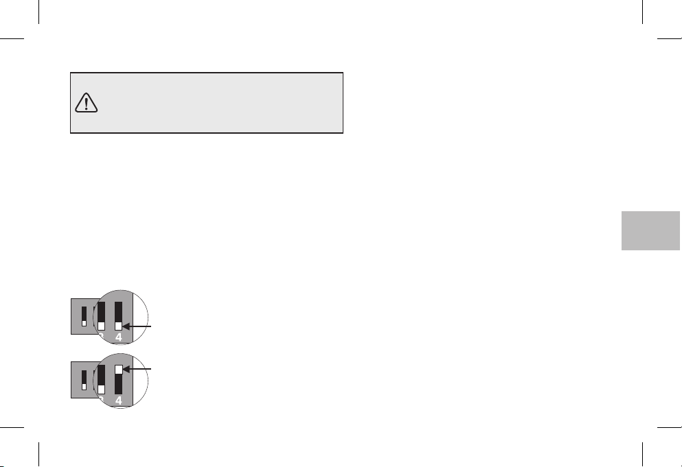
15 - ÉCHELLE DE TEMPÉRATURE °C ou °F 16 - AVERTISSEMENTS
ATTENTION : le chronothermostat a été réglé en
usine pour utiliser les degrés Celsius (degrés
centigrades) et peutêtre modifiépar l'installateur
ou un utilisateurexpert endegré Fahrenheit(°F).
Le micro-interrupteur placé à l'arrière du chronothermostat a
été configuré en usine sur la position (degrés
4
OFF
centigrades).
Vous pourrezle déplacer surla position : L'écran affichera,
ON
après avoir effectué une opération de RESET, la température
ambiante et lesParamètresen degrésFahrenheit(°F).
Pour revenir à l'affichage en degrés centigrades, remettre le
micro-interrupteur sur et effectuer une opération de
4 OFF
RESET.
Dans les deux cas, programmer de nouveau le
chronothermostat comme indiquédans le chapitre10).
ON
OFF = échelle des Degrés centigrades (°c)
432
ON
1
432
1
(paramètres d'usine)
ON = échelle des Degrés Fahrenheit (°F)
Lire attentivement le présent livretd’instructions d'utilisation
et le conserverpour toute consultationultérieure.
Les figures présentes dans le manuel représentent l'écran
avec les paramètres de l'échelle des températures en °C
(degrés Celsius).
Si l'écran affiche la valeur de la température ambiante
00.0 °C ou 50.0 °C
température mesurée est supérieure ou inférieure aux
valeurs maximum del'échelle
Utiliser exclusivement des piles alcalines de 1,5V, de type
AA LR6 (non incluses dans l'emballage). L'emploi de
piles d'un autre type peut entraîner la perte des données
programmées.
N.B. : le produit a été testé et ses caractéristiques sont
garanties avec des piles alcalines DURACELL ou
ENERGIZER.
Important :
Il esttoutefois conseilléde les remplacer au moinstous les
24 mois pour éviter qu'elles ne s'épuisent pendant des
périodes d'absence (ex.Vacancesde Noëletc.)
Au besoin, nettoyer le chronothermostat à l'aide d'un
chiffon légèrement humide.
Le fabricant se réserve la faculté d’apporter, sans
obligation de préavis, les modifications qu’il jugera
nécessaires à laconstruction.
la duréedes piles peut être supérieureà 2ans.
, en clignotant, il signale que la
.
FR
35
Page 36

1 - TECHNISCHE DATEN
Betriebsspannung:
Netzunabhängigkeit, Betriebsdauer:
Netzunabhängigkeit ab dem Erscheinen des Symbols
Batterien entladen:
Zu- und Abschaltung, Gerät:
Softwareklasse:
Nenn-Impulsspannung:
Ausgang:
Querschnitt der Leiter zu den Relaisklemmen:
Eingang für Telefonschaltung:
Querschnitt der Leiter zu den Telefonschaltungsklemmen:
Schutzklasse:
Schutzart:
Anz. programmierbaren Anzeigen auf dem Uhrkranz:
Mit "Reitertasten" programmierbare Mindestzeit:
Verschmutzung:
Skala für Temperatureinstellung mittels Drehknöpfe:
K
- omfort:
t
- Nacht (Energieersparnis):
t
Temperaturbegrenzung (Sperre Sollwert t max):
Frostschutztemperatur ( ):
Genauigkeit der Temperaturregelung:
DE
Skala für Anzeige der Umgebungstemperatur:
Ablesetoleranz der Umgebungstemperatur
Betriebstemperaturbereich:
Lagerungstemperaturbereich:
Thermischer Gradient:
Temperaturregelungsart:
Genauigkeit der Uhr:
Richtlinien für CE-Zeichen:
36
t
2 Stk. Alkali-Stabbatterien 1,5 V Typ AA LR6 ( )
2 Jahre
1 Monat
1 / BU / Elektronisch
Klasse A
4 kV
Relais mit Wechselkontakt Schließer / COM / Öffner
potentialfrei - max 5(3)A / 250 Vac
0,75 + 2,5 mm
für Schließkontakt potentialfrei
0,5 ÷ 1,5 mm
Klasse II
IP 30
48
1/2h
Normal
+5 ÷ +30 °C (default +20 °C) / +41 ÷ +86 °F (default +68 °F)
+5 ÷ +30 °C (default +17 °C) / +41 ÷ +86 °F (default +62,6 °F)
Step 0,1°C / 0 ,1 °F
+5 °C / 41 °F (fix, nicht regulierbar)
± 0,1 °C / ± 0,1 °F
0 ÷ +50 °C / +32 ÷ +122 °F
± 0,5 °C / ± 0,9 °F
0 ÷ +50 °C / +32 ÷ +122 °F
-20 ÷ +65 °C / -4 ÷ +149 °F
max 1K / 15 min.
ON-OFF-Betrieb mit auf 0,3 - 0,5 - 0,7 - 0,9 °C einstellbarem Differentialwert
Proportionalbetrieb mit einstellbaren Zeitzyklen 7-10-15-20 Minuten
± 1 Sek./Tag
LVD und EMC EN60730-2-7 EN60730-2-9
2
2
empf. Marken DURACELL oder ENERGIZER
Page 37
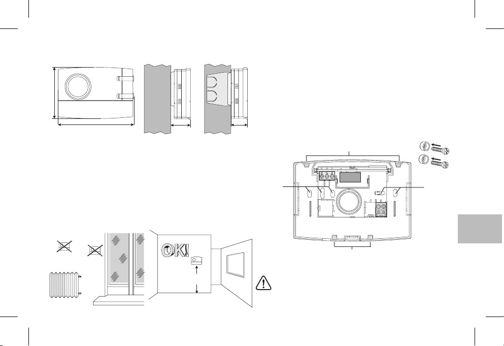
2 - ABMESSUNGEN
82
121,5
31,5 26
3 - INSTALLATION
Installation des Zeitthermostats:unabhängig-ortsfest
An Wand - auf runder Dose - halb eingebaut auf rechteckiger
Dose 3 Module.
Die Vorrichtungca. 1,5 müber dem Bodenund nicht inder Nähe
von warme Quellen,Fensternoder anderenObjekten, dieden normalen Betrieb beeinträchtigenkönnen, installieren.
!
h 1,5 m
4 - BEFESTIGEN DER GRUNDPLATTE AN DER WAND
Die zusteuernde Vorrichtungvom Stromnetz trennen
Die Grundplatte an der Wand, der runden oder rechteckigen
Einbaudose durchdie passenden Löcherpaare anschrauben.
Sollte die Wand, an der die Grundplatte des Zeitthermostats befes-
tigt werden muss, aus Metall sein, sind die zwei Schrauben mit den
zu diesemZweck vorgesehenen Isolierscheibenzu versehen.
A
A - Befestigungslöcher
B - Kabeldurchlass rundes, rechteckiges Gehäuse
C - Befestigungsklauen
C
3
A A
21
4
5
6789
B
C
Für die korrekte Befestigung des Zeitthermostats an der
Grundplatte für die Wandbefestigung darf die Platte nicht
durch zu starkes Anziehen der Schrauben zum Befestigen
an der rechteckigenoder runden Einbaudoseverformt sein.
DE
37
Page 38
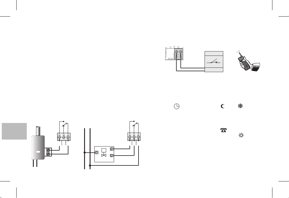
5 - ELEKTRISCHE ANSCHLÜSSE
Wichtig: die Installation und der elektrische Anschluss der Geräte muss
durch qualifiziertes Fachpersonal und imEinklang mit dengeltenden Normen und gesetzlichen Bestimmungen ausgeführt werden. Der Hersteller
übernimmt keine Verantwortung für die Verwendung von Produkten, für
deren Einsatz bestimmte Umgebungsbedingungen oder Installationsrichtlinien erfülltsein müssen.
Hinweis für den Installationstechniker: Bei Installation auf einer Fläche
(z. B. Wand) ist eine angemessene Verlegung der Kabel nach den gesetzlichen Anlagenauflagen vorzusehen. Die Last des Relais darf auf keinen Fall
den inden technischen Datenangegebenen Wert überschreiten.
Die zu steuernde Vorrichtung vom Stromnetz trennen.
Die zu steuernde Vorrichtung an die folgenden Klemmen
anschließen
:
1-gemeinsam
2-3-Kontakt Ruhestellung geschlossen
Kontakt Ruhestellung offen
Beispiel für elektrische Anschlüsse
Anschluss an einen
Durchlauferhitzer
NO
G
NG
Anschluss an ein
motorgesteuertes Ventil
230V~
NNGL
NO
DE
38
KESSEL
L
N
230V~
231
M
LAST
ÖFFNET
SCHLIEßT
Anschluss einer Telefonschaltung für Fernsteuerung
Die Klemmen und des Zeitthermostats dienen zum
Anschließen einer Telefonschaltung mit in Ruhestellung offenem
Kontakt.
89
6789
Beisp.
Telefonschaltung
Kontakt
Betrieb mit Telefonschaltung
Der telefonische Programmierer steuert den Zeitthermostat,
indem der den an die Klemmen und angeschlossenen
89
Kontakt schließt.
Zum Aktivieren des Zeitthermostats über die Telefonschaltung
muss der Umschalter auf eine der folgenden Betriebsarten
eingestellt sein: AUTOMATISCH oder oder .
Wird derProgrammierer aktiviert (Kontakt anden Klemmen8 und 9
t
geschlossen), schaltet der Thermostat von einer der mit dem
Umschalter eingestellten Bedingungen
G
Komforttemperatur um
: auf demDisplay erscheint außerallen 48
auf Betrieb immer mit
eingeschalteten Anzeigen das Symbol für die aktivierte
Telefonschaltung und dasblinkende Komfort-Symbol .
Deaktivierung der zwangsweisen Umschaltung durch die
231
Telefonschaltung
Den Kontakt der Telefonschaltung öffnen (siehe Anleitung des
Programmierers), damit der Thermostat wieder die zum Zeitpunkt
der Aktivierung vorliegendeEinstellung hat.
Anm.: der Aktivierung- bzw. Deaktivierungsbefehl wird innerhalb 1 Minute
operativ.
t
Page 39
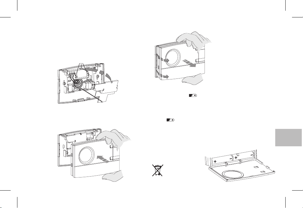
6 - BEFESTIGEN / ABNEHMEN DES THERMOSTATS VON DER GRUNDPLATTE
Die Kabelabdeckung anbringen; dazu den Zahn in die
Vertiefung der Grundplatte setzen und die Abdeckung durch
leichtes Drücken aufdie Haken einrasten lassen.
E
F
Zum Abnehmender Abdeckung einen kleinen Schraubendreher
an den Haken ansetzen.
F
F
D
Zum Abnehmen des Thermostats
von der Wandplatte den
Thermostat wie abgebildet anfassen unddurch Drehen nach rechts
abziehen.
E
D
Den Thermostatauf dieGrundplatte setzen; daraufachten, dass
die Kontakte richtig eingesetzt sind; sanft andrücken, bis das
Einschnappen der Befestigungszähnchenzu hören ist.
7- EINLEGEN / AUSWECHSELN DER BATTERIEN
Das Erscheinen des Symbols deutet darauf hin, dass
die Batterienschwächer werden.Von diesem Momentan haben Sieetwa
30 TageZeit, umsie auszuwechseln.
Blinkend Wenn in dieser Zeit die fast leeren Batterien nicht
ausgewechselt wurden, schaltet sich das Display ab und zeigt nur das
Symbol an.durchgehend leuchtend
Jegliche Temperaturregelung wird unterbrochen und alle Einstellungen werden
gespeichert, um beim Einsetzen derneuen Batterien abrufbereit zu sein.
Die entladenen Batterien durch zwei 1,5 AA (LR6)
ersetzen; .
die Polebeachten
ACHTUNG: zum Auswechseln der Batterien hat man ungefähr 1 Minute
Zeit, danach gehen die
gespeicherten Daten verloren.
Die alten Batterien
vorschriftsmäßig
entsorgen.
blinkenden
V-Alkalibatterien
DE
39
Page 40
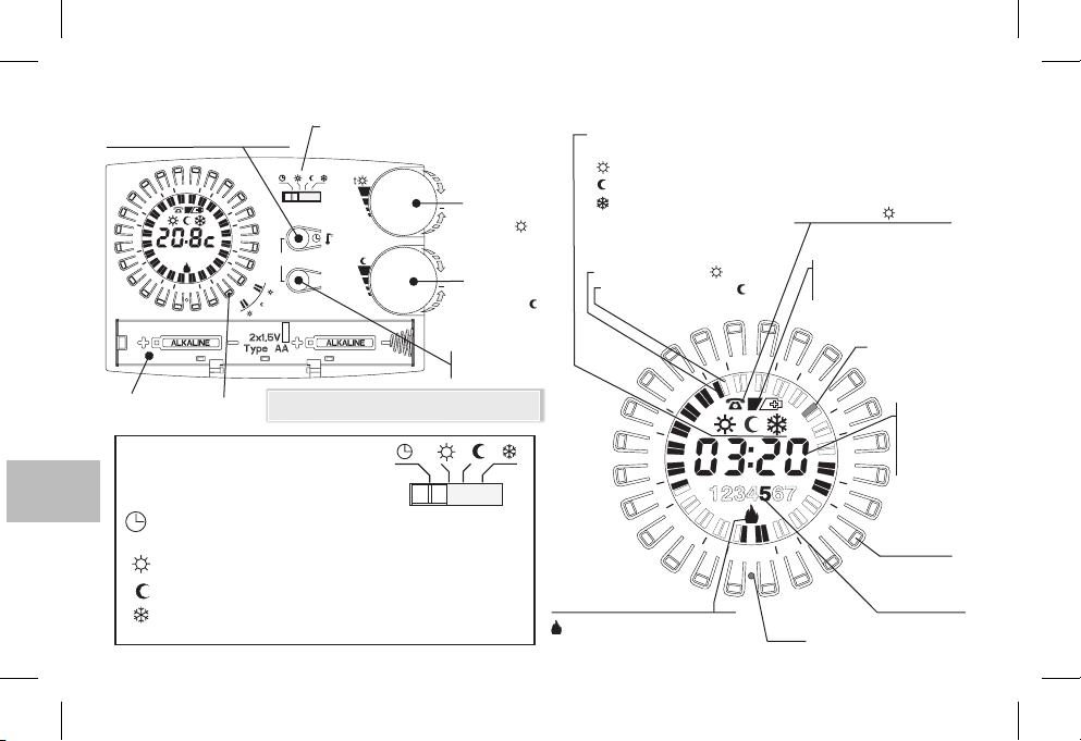
8 - ANSICHT, LEGENDE DISPLAY UND TASTENFUNKTIONEN
Einstelltaste: Stunden-Minuten
oder Anz. der Umgebungstemperatur
4
2
21
8
1
15
Batteriefach
1234567
2
1
R
3
6
9
t
Reitertaste
MIT UMSCHALTER
WÄHLBARE BETRIEBSART
Umschalter- Wechselschalter - Betriebsmodus
(für Details siehe Kasten unten)
t
t
t
/
copy
t
t
Hinweis: weitere spezielle Tastenfunktionen werden
in denjeweiligen Abschnittenbeschrieben.
t
Day
(5 ÷ 30 °C)
Drehknopf
+
Sollwerttemperatur
Komfort
(5 ÷ 30 °C)
Drehknopf
+
Sollwerttemperatur
Abnahme
(Sparmodus)
Tageswähltaste
(Wochenmodus)
Anzeige des aktuellen
Betriebsmodus:
Komfort
Nacht
Frostschutz
t
t
Anzeige des eingeschalteten
Programms
Anzeige leuchtet = Komfort
Anzeige leuchtet nicht = Nacht
ttt
DE
AUTOMATISCH - einstellbar von 5 bis 30 °C;
Immer, regelbar von 5 bis 30 °C (alle 48 Anzeigen leuchten)Komfort
t
Immer, regelbar von 5 bis 30 °C (alle 48 Anzeigen ausgeschaltet)Nacht
t
Immer, Frostschutz Festtemperatur-Einstellung auf 5 °C
t
40
Komfort oder Nacht
je nach Programmierung der Anzeigen mit Reitertasten
(alle 48 Anzeigen ausgeschaltet)
Anzeige Verbraucherstatus
Blinken = Relais aktiviert
abgeschaltet = Relais deaktiviert
Aktivierung über
Telefonschaltung
(mit blinkender Anzeige)
Batterieanzeige:
fast leer
- (blinkend)
leer
- (durchgehend leuchtend)
Anzeige laufende
3
9
½ Std.
6
Ta g
(Wochenmodus)
Bsp. 5 = Freitag
Aktuelle Uhrzeit
oder gemessene
Umgebungstemperatur /
Sollwerttemperatur
bei der Einstellung
Reitertaste
4
2
21
8
1
15
1
2
R
Reset
Page 41
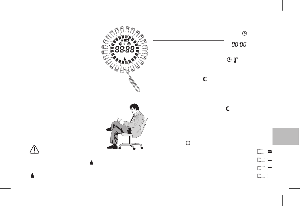
9 - RESET
Beim ersten EinschaltenRoder wenn
der Zeitthermostateigenartige Anzeigen
hat oder falsch funktioniert usw., einen
max. 1mm starkenStab in das mit gekennzeichnete Loch auf dem Kranz zwischen den Reitertastenstecken und kurz
drücken. Das Display aktiviert für ein
paar Sekunden alleSegmente, wie inder
nebenstehenden Abbildung gezeigt,
und alle gespeicherten Daten werden
gelöscht und auf die Werkseinstellung
zurückgesetzt (mit Ausnahme der
Einstellungen mit Mikroschaltern).
Der Zeitthermostat kann nun neu programmiert werden (siehe Kapitel 10).
4
2
21
8
1
15
123 5674
3
6
9
1
2
R
Vereinfachte Programmierung
Alle im folgenden Abschnitt beschriebenen Vorgänge können vor dem Befestigen
des Thermostats an der Wandplatte
ausgeführt werden; daher kann die
Programmierung ganz bequem im Sitzen
vorgenommen werden.
ACHTUNG !
Erfolgt die Programmierung vor der Befestigung an der Wandplatte, kann es
sein, dass die Anzeige auf dem Display (ausgeschaltet oder blinkend) nicht
dem wirklichen Relaisstatus entspricht. Binnen ab der
Befestigung ander Wandplatte schaltetsich das Relaisder Displayanzeige
(Ausgeschaltet oderblinkend) entsprechend ein.
maximal einer Minute
10 - PROGRAMMIERUNG
Den Umschalter auf Betriebstellen .
WICHTIG: einen RESETvornehmen
Nach einigen Sekunden blinktauf dem Display undnun kann
man wie folgtdie Uhrzeit in Stundenund Minuteneingeben.
Einstellen der aktuellenUhrzeit (Stunden undMinuten)
Zum Programmieren derUhrzeit die Taste drücken:
- durch anhaltendes Drückenstellt mandie Stundenein;
- durch wiederholtes kurzesDrücken stelltman dieMinuten ein;
(auf dem Modell mit Tagesprogrammierung 5 Sekunden warten, bis
auf dem Display das Symbol erscheint und die der
programmierten Zeit entsprechende blinkende h Anzeige).
Einstellen des aktuellen Wochentages
(nur bei Modell mit Wochenprogrammierung)
Auf dem Display wird der Tag blinkend für Montag angezeigt.
Mit der Taste den aktuellen Wochentag auswählen
(5 Sekunden warten, bis das Symbol erscheint und die der
programmierten Zeitentsprechende blinkende 1/2-Stunde-Anzeige).
Programmieren der Komforttemperatur zu den
gewünschten Uhrzeiten
Die in Kranzform auf dem Display angeordneten Reitertasten
und wieder loslassen
Komforttemperatur aktiviert werden soll (die Komforttemperatur wird
mit demRegler eingestellt), hierbei wiefolgt verfahren:
1 Maldrücken und wiederloslassen zu Aktivierender vollenStunde
2 Mal drücken und wieder loslassen zu Aktivieren der ersten halben Stunde
3Maldrücken und wieder loslassen zu Aktivieren der zweiten halben Stunde
4 Mal drückenund wieder loslassenzu Deaktivieren dervollen Stunde
AUTOMATISCHEN
/
½
1
Day
, die den Zeiten entsprechen, zu denen die
t
drücken
DE
41
Page 42
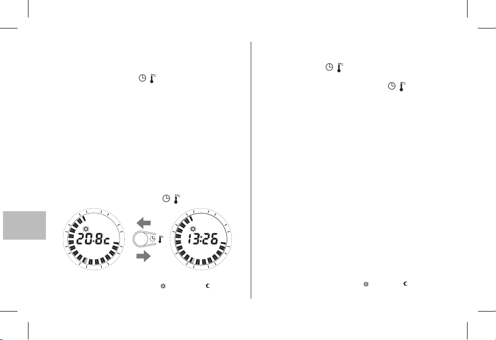
Kopieren des Programms für mehrere Tage
(Nur bei Modell mit Wochenprogrammierung)
Nach der Programmierung des Tages kann man diese
Einstellung auf den nächsten Tag kopieren (copy): dazu drückt
man gleichzeitig dieTasten
Zum Einstellen anderer Programme wählt man den Tag mit der
Taste und programmiert diesen dann durch Drücken der
Day
Reitertasten (s. Oben).
Aufschalten von eingefügten Programmen für die Wochentage
(nur bei Modell mit Wochenprogrammierung)
Day
Die Taste mehrmals drücken und wieder loslassen.
/
und .
Day
Anm.: Nach der Programmierung oder dem Aufschalten versetzt
sich der Thermostat 5 Sekunden nach dem letzten Drücken einer
Taste automatisch in den Betriebsmodus (Anzeige der laufenden
½ h blinkt).
Man kann jederzeit von der Anzeige der laufenden Uhrzeit auf die
Anzeige der Umgebungstemperatur (°C) umschalten und
umgekehrt, indem man kurz die Taste drückt.
4
2
21
1
3
/
4
2
21
3
DE
8
1
6
3
15
Anzeige der Sollwerttemperatur t und/oder t eingestellt
Siehe Abschnitt 11
42
9
2
1
1
8
1
/
3
15
9
2
21
1
ÄNDERN DER EINSTELLUNGEN
Ändern der aktuellenUhrzeit
Halten Sie die Taste solange drücken, bis die laufende
Uhrzeit blinkt.
Stunden und/oder Minuten mit der Taste wie oben
/
beschrieben korrigieren.
Ändern des Wochentages
(nur bei Modellen mit Wochenprogrammierung)
Halten Sie die Taste drücken, bis die dem Wochentag
Day
entsprechende Zahl blinkt.
Den neuen Tag mit der Taste einstellen.
Day
Ändern der eingegebenen Programme
Modell mit Tagesprogrammierung
Zum Ändern des Programms direkt die Reitertasten
wie oben beschriebenbenutzen.
Modell mit Wochenprogrammierung
Das Tagesprogramm direkt mit den Reitertasten
wie oben beschriebenkorrigieren.
Zum Korrigieren des Programms der anderen Wochentage
mit der Taste den gewünschten Wochentag auswählen
6
und diesen direkt mit den Reitertasten wie oben beschrieben.
Programmieren.
Day
Anm.: 5 Sekunden nach dem letzten Drücken einer Taste schaltet
der Thermostat automatischwieder auf Betriebum (laufende V2 h Anzeige blinkt).
Änderung der Sollwerttemperaturt und/oder t eingestellt
Siehe Abschnitt 11
/
Page 43
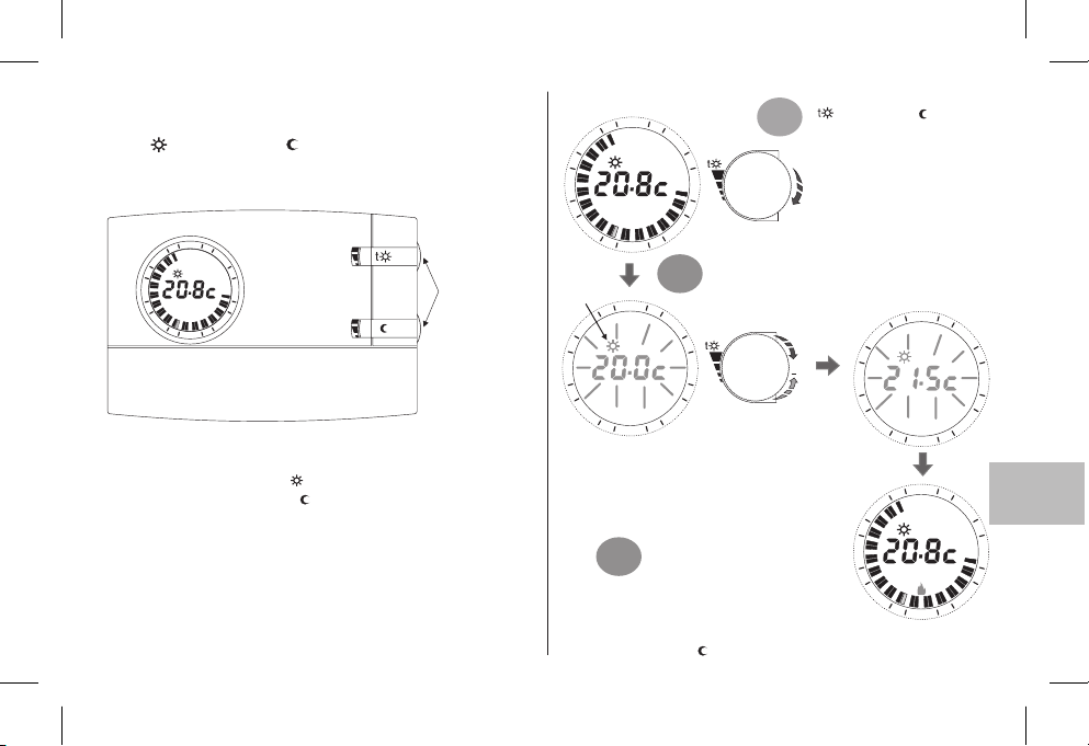
11 - ANZEIGE/ÄNDERUNG DER
SOLLWERTTEMPERATUREN
(mittels Drehknopf):
t KOMFORT / t ABNAHME
Normalerweise zeigt das Display die gemessene
Umgebungstemperatur oder dieaktuellen Uhrzeit an.
4
2
21
3
8
1
15
6
3
9
1
2
t
Beim ersten Einschaltender Raumthermostatuhroder nachdeinem
Reset, gelten dieim Werk voreingestelltenSollwerttemperaturen:
Sollwerttemperatur Komfort t 20.0 °C/ 68.0°F (obererDrehknopf)
=
Sollwerttemperatur Abnahme t = 17.0°C /62.6°F (obererDrehknopf)
Zum Anzeigen der aktuellen Sollwerte ist es, unabhängig vom
momentanen Betriebszustand der Raumthermostatuhr,
ausreichend, den entsprechenden Drehknopf leicht zu drehen, bis
der Sollwert blinkt; nach 5 Sek. kehrt das Display zu den normalen
Betriebsbedingungen zurück. Wenn die eingestellten Sollwerte
nicht Ihren Anforderungen entsprechen, können sie zu jedem
Zeitpunkt nach Belieben zwischen +5°C und +30 °C (+41 °F und
+86 °F) verändertwerden, wie nebenstehendbeschrieben.
Die Drehknöpfe
können gedreht
werden, ohne dass
dazu die Klappe
geöffnet werden
muss.
Den gewünschten Drehknopf
4
2
1
21
8
1
3
6
( Komfort oder Abnahme)
1°
leicht drehen, umden aktuellen
Temperatursollwert anzeigen
zu lassen und den
Einstellvorgang zubeginnen.
t
3
15
Anzeige des zu
verändernden
Sollwertes
21
8
1
15
Hinweis: wenn eine Temperaturgrenze eingestellt wurde
(siehe nächster Abschnitt) kann der Sollwert nur bis zu
diesem erhöhtwerden (Sperre).
3°
Zum Einstellen des Temperatursollwertes Abnahme genauso, aber
mit dem Drehknopft verfahren.
9
1
1
2
4
2
1
2
Der gewünschteSollwert beginntzu blinken,dann
den Drehknopf im Uhrzeigersinn zum Erhöhen
bzw. entgegen dem Uhrzeigesinn zum Verringern
2°
des Wertes drehen (die Variation erfolgt in
Schritten von0,1°C/0,1 °F).
3
6
9
Die so festgelegte
Temperatur wird der neue
Bezugssollwert.
Nach Verstreichen von etwa 5 Sek.
nach demDrehen desDrehknopfes
kehrt das Display zu den normalen
Betriebsbedingungen zurück:
4
2
21
+
8
1
15
1
2
4
2
1
21
8
1
3
15
1
1
2
3
6
9
DE
3
6
9
43
Page 44
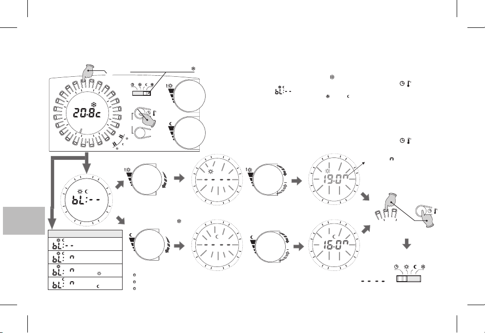
12 - BEGRENZUNG (SPERRE) DES MAX. TEMPERATURSOLLWERTES KOMFORT UND/ODER ABNAHME
In besonderen Fällen der Installation der Raumthermostatuhr, z.B. in öffentlichen Gebäuden, Hotels, usw., könnte es nützlich sein, die max. Temperatursollwerte zu begrenzen, um falsche
Einstellungen von Seiten nicht autorisierten Personals zu verhindern.
Den Wechselschalter auf t stellen
4 s lang gleichzeitig drücken.
3
6
copy
9
t
t
t
3
6
und/oder
9
t
t
t
t
/
t
Day
Wichtig: Verstreichen 20 Sek., ohne dass der Drehknopf gedreht wird, verlässt das Gerät automatisch den
Programmiermodus für die Sperre, ohne dass die Einstellungen gespeichert werden, und kehrt
Frostschutzmodus (t )
Hinweis:
In der Basiskonfiguration ist keinerlei Sperre eingestellt.
Um eventuell zuvor eingestellte Sperren aufzuheben, die Temperatursollwerte wie folgt einstellen:
Der Resetbefehl annulliert eventuell eingestellte Sperren
DE
44
Taste 23 Uhr
4
2
21
8
1
12 45673
15
2
1
R
4
2
21
8
1
15
1
2
Mögliche Anzeigen
Keine Sperre
(Werkseinstellung)
Sperre für beide
Sollwerte
Sperre nur für
Sollwert t Komfort
Sperre nur für
Sollwert t Abnahme
Es ist nun möglich, die max. Temperatursollwerte (Komfort und/oder Abnahme) wie folgt zu
begrenzen.
1
- Den Wechselschalterauf den Frostschutzmodus t stellen (fixer Sollwertbei +5°C, nicht veränderbar)
2
-Für4sgleichzeitig die Taste, die auf dem Kreis 23 Uhr entspricht, und die Taste drücken; auf
dem Display erscheint: (z.B. Werkseinstellung = keineSperre).
3
- Den Drehknopf des gewünschten Sollwertes (t oder t ) leicht drehen, um den aktuellen Sollwert
anzeigen zu lassen.
4
- Der Sollwert beginnt zu blinken und nach3 Sek. kann die Sperre (Begrenzung) zwischen +5,1°C und
+29,9°C eingestellt werden;dazu den Drehknopf im Uhrzeigersinnzum Erhöhen bzw.entgegen dem
Uhrzeigesinn zum Verringern des Wertesdrehen (die Variationerfolgt dabei in Schritten von0,1.
5
- Wenngewünscht, die unter 3 und4 beschriebenen Schritte mitdem anderen Drehknopf wiederholen.
6
- Innerhalb von 20 Sek. die Einstellung(en) speichern und den Programmiermodus verlassen; dazu 4
Sek. lang gleichzeitigdie Taste,die auf dem Kreis23 Uhr entspricht, und dieTaste drücken.
7
- Den Wechselschalter wieder aufden gewünschten Betriebsmodus stellen.
4
2
21
8
1
15
21
8
1
15
3
6
9
2
1
4
2
3
t
6
9
2
1
+
+
4
2
21
8
1
15
2
1
4
2
21
8
1
15
2
1
Das Symbol zeigt die max. begrenzbare
3
Temperatur sowohl für die °C- als auch
für die °F-Skala an.
6
Zum Speichern der Einstellung(en) und
Verlassen des Programmiermodus
9
3
9
Sekunden lang drücken
6
Den Wechselschalter wieder auf den
gewünschten Betriebsmodus stellen
42
Gleichzeitig 4
t
/
/
t
t
/
Page 45
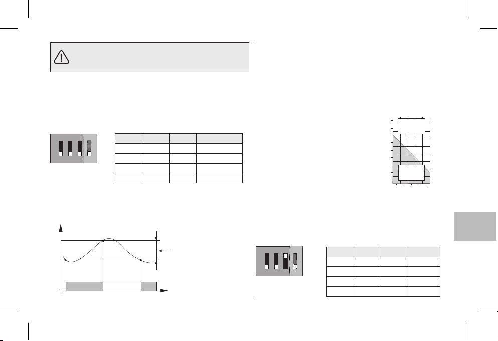
Die Einstellungen der Mikroschalter (Dip-switch) auf
der Geräterückseite dürfen nur von einem Fachmann
vorgenommen werden.
13 - TEMPERATURDIFFERENTIAL
Der Zeitthermostat funktioniert nach einem Differentialmodus
ON-OFF (Dip 3 in Stellung OFF), wobei der Differentialwert
werkseits auf (0,54 °F)festgelegt ist.0,3 °C
Der Differentialwert kannmit den Mikroschaltern(Dip-switch) wie in
der Tabelleangegeben geändertwerden.
ON
ON
ON
1
1
Der Differentialwert richtet sich nach der thermischen Trägheit der
Anlage; fürAnlagen mit Heizkörpern(z. B. aus Gusseisen) sollteder
Wert niedrig, für Anlagen mit Gebläse sollte er hoch eingestellt
werden.
°C
Gemessene Temperatur
ON
Dip 1 Dip 2 Dip 3
OFF OFF OFF
32
32
4
OFF ON OFF
OFF
OFF
ON OFF OFF
ON ON OFF
Einstellbares Differential
0,3 °C - 0,5 °C - 0,7 °C - 0,9 °C
(0,54 °F - 0,9 °F - 1,26 °F - 1.62 °F)
OffOn On
Zeit
Differential
0,3 °C (0,54 °F)
0,5 °C (0,9 °F)
0,7 °C (1,26 °F)
0,9 °C (1,62 °F)
14 - PROPORTIONALBETRIEB
Als Alternative zum Differentialmodus kann die Temperatur auch
proportional geregelt werden (Dip 3 in Stellung ON); mit diesem
System kann man den Energieverbrauch reduzieren und auch den
Verschleiß des Brennersdurch selteneres Einschalten optimieren. Die
Dauer dereinzelnen Einschaltungen hängtnicht nur vom eingestellten
Zyklus ab, sondern auch vom Unterschied zwischen der
Solltemperatur und derIsttemperatur (siehe Beispiel).
Einstellungsbeispiel t =20 °C - Zyklus =10 min
t = 20,5 °C Verbraucherimmer ausgeschaltet
t = 20,4 °C Verbraucher 1 min ON - 9 min OFF
t = 20,3 °C Verbraucher 2 min ON - 8 min OFF
t = 20,2 °C Verbraucher3 min ON- 7min OFF
t = 20,1 °C Verbraucher4 min ON- 6min OFF
t = 20,0 °C Verbraucher5 min ON- 5min OFF
t = 19,9 °C Verbraucher6 min ON- 4min OFF
t = 19,8 °C Verbraucher7 min ON- 3min OFF
t = 19,7 °C Verbraucher8 min ON- 2min OFF
t = 19,6 °C Verbraucher9 min ON- 1min OFF
t = 19,5 °C Verbraucherimmer eingeschaltet
Die Zyklusdauerwird von derStellung derMikroschalter (Dip-switch)
auf der Geräterückseite wiein der Tabelle angegeben bestimmt.Für
thermisch träge Anlagen (z. B. mit Gusseisen-Heizkörpern,
Fußbodenheizungen) sollte der Zyklus lang sein, für Anlagen mit
geringer thermischerTrägheit(Gebläse) sollte er kurz sein.
ON
ON
Dip 1 Dip 2 Dip 3
OFF OFF ON
4
32
1
OFF ON ON
OFF
ON OFF ON
ON ON ON
°C
20,8
Verbraucher
OFF
20,6
20,4
20,2
20,0
19,8
19,6
Verbraucher
19,4
ON
19,2
01024 6 8 Minuten
Zyklusdauer
7 min
10 min
15 min
20 min
DE
45
Page 46
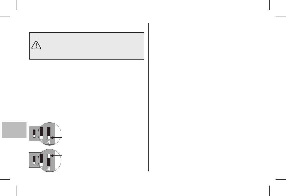
15 - TEMPERATURSKALA °C oder °F 16 - HINWEISE
ACHTUNG: Die Raumthermostatuhr ist im Werk
für den Betrieb in Grad Celsius eingestellt und
kann vom Installateur oder erfahrenen Nutzer in
Grad Fahrenheit (°F) umgewandelt werden.
Der Mikroschalter auf der Rückseite der Raumthermostatuhr
wird imWerk auf (Grad Celsius) gestellt.
Er kann auf umgestellt werden: das Display zeigt dann, nach
4
OFF
ON
Durchführung einesRESET-Vorgangs,die Umgebungstemperatur
und dieSollwerte in GradFahrenheit (°F)an.
Um zur Anzeige in Grad Celsius zurückzukehren, den
Mikroschalter wieder auf stellen und ein RESET
4 OFF
durchführen.
In beiden Fällen die Raumthermostatuhr entsprechend den
Anweisungen in Kapitel10 neu programmieren).
ON
DE
OFF = Skala in Grad Celsius (°c)
432
1
ON
432
1
46
(Werkseinstellung)
ON = Skala in Grad Fahrenheit (°F)
Bitte lesen Sie diese Installations- und
Gebrauchsanleitungen aufmerksam und bewahren Sie sie
sorgfältig auf, um später darin nachschlagen zu können.
Die Abbildungen der Anleitung stellen das Display mit
Temperaturangaben in °C(Grad Celsius)dar.
Blinkt auf dem Display der Raumtemperaturwert
oder 50.0 °C Temperatur über den
Grenzwerten.
Nur 1,5V-Alkalibatterien vom Typ AA LR6 (nicht in der
Packung enthalten), benutzen; andere Batterien können
zur Folge haben,dass dieProgrammierung gelöschtwird.
NB: der Thermostat wurde vom Hersteller auf seine
Funktionstüchtigkeit mit Alkalibatterien der Marke
DURACELL oder ENERGIZER getestet.
die Lebensdauer der Batterien kann auch mehr
Wichtig:
als 2 Jahre betragen. Es wird dennoch empfohlen, sie
mindestens alle 24 Monate auszuwechseln, um zu
vermeiden, dass sie sich während der
Abwesenheitsphasen. (beispielsweise während der
Weihnachtsferienusw.)Entleeren.
Zum Reinigen des Zeitthermostats ein leicht
angefeuchtetes Tuchbenutzen.
Der Hersteller behält sich das Recht vor, notwendige
technische Änderungen ohne Vorankündigung
vorzunehmen.
, liegt die gemessene
00.0° C
Page 47

1 - DATOS TÉCNICOS
Tensión de alimentación:
Autonomía:
Autonomía desde el encendido del símbolo pilas agotadas:
Tipo de acción, desconexión y aparato:
Software:
Tensión de impulso nominal:
Tipo de salida:
Sección de los cables a los bornes:
Entrada para programador telefónico:
Sección de los cables a los bornes del programador telefónico:
Tipo de aislamiento:
Grado de protección:
N° de índices programables sobre la corona del reloj:
Tiempo mínimo programable con las teclas "caballete":
Contaminación:
Escala de regulación de la temperatura
n
- Co fort:
t
R
- educción (ahorro):
t
Limitación de temperatura (bloqueo set. t. máx.):
Temperatura antihielo ( ):
Precisión de regulación de la temperatura:
Escala de visualización de la temperatura ambiente:
Tolerancia lectura de la temperatura ambiente:
Límites de la temperatura de funcionamiento:
Límites de la temperatura de almacenaje:
Gradiente térmico:
Tipo de regulación dela temperatura:
Precisión del reloj:
Normas de referencia para la marca CE:
t
con ruedas:
2 pilas alcalinas de 1,5 V tipo AA LR6
2 años
1 mes
1 / BU / Electrónico
de Clase A
4 kV
relé con contacto en intercambio NA / COM / NC
libre de potencial - máx 5(3)A / 250 Vac
0,75 + 2,5 mm
para contacto NA libre de potencial
0,5 + 1,5 mm
clase II
IP 30
48
½ h
normal
+5 ÷ +30 °C (default +20 °C) / +41 ÷ +86 °F (default +68 °F)
+5 ÷ +30 °C (default +17 °C) / +41 ÷ +86 °F (default +62,6 °F)
Step 0,1°C / 0 ,1 °F
+5 °C / 41 °F (fija no regulable)
± 0,1 °C / ± 0,1 °F
0 ÷ +50 °C / +32 ÷ +122 °F
± 0,5 °C / ± 0,9 °F
0 ÷ +50 °C / +32 ÷ +122 °F
-20 ÷ +65 °C / -4 ÷ +149 °F
máx 1K/ 15 min.
funcionamiento ON-OFF con diferencial programable a 0,3 - 0,5 - 0,7 - 0,9 °C
funcionamiento proporcional con ciclos de tiempo programable 7-10-15-20 minutos
± 1 seg./día
LVD y EMC EN60730-2-7 EN60730-2-9
2
2
(se recomiendan pilas DURACELL o ENERGIZER)
ES
47
Page 48
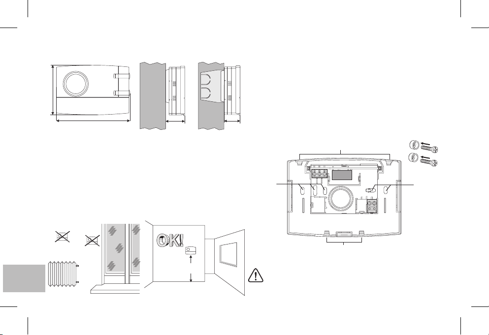
2 - DIMENSIONES MÁXIMAS
82
121,5
31,5 26
3 - NORMAS PARA LA INSTALACIÓN
Instalación del cronotermostato: independiente-fijo
De pared, en caja redonda, semiempotrable en caja rectangular
de 3 módulos.
Instale el dispositivo a 1,5 m del suelo, lejos de fuentes de calor,
ventanas y de aquello que pueda influir en el funcionamiento
Normal.
4 - FIJACIÓN DE LA BASE DE PARED
Desactive latensión de reddel dispositivoque desea controlar.
Fije con los tornillos la base: a la pared, a la caja empotrable redon-
da o rectangular utilizandolos pares deorificios .
Si la pared donde se va a fijar la base del cronotermostato es
metálica, insertelas arandelas aislantesen losdos tornillos.
A
A - orificios de fijación
B - paso de cables desde la caja redonda, rectangular
C - pestañas de fijación del cronotermostato
C
3
A A
21
4
5
6789
B
ES
48
!
h 1,5 m
C
Para asegurar el montaje correcto del cronotermostato en
la base, la pared no debe presentar curvaturas porque se
han apretado en exceso los tornillos de fijación a la caja
rectangular o redonda empotrada en la pared.
Page 49
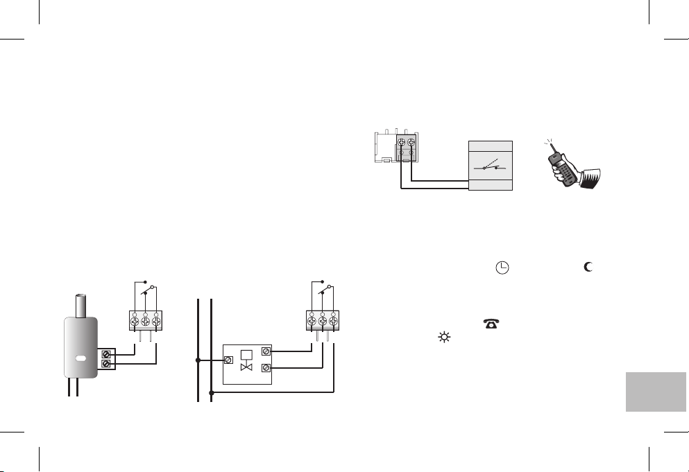
5 - CONEXIONES ELÉCTRICAS
Importante: la instalación y laconexión eléctricade losdispositivos
y equiposdeben ser realizadas porpersonal cualificadoy conforme
con las normas y leyes envigor. El fabricante declina cualquier responsabilidad sobre el uso de productos que deben seguir normas
medioambientales y requiereninstalaciones especiales.
Nota para el instalador: en caso de montaje sobre una superficie
(por ejemplo,sobre una pared),es necesario prever una canalización
adecuada de los cables, según las normas de instalación vigentes.
Verifique que la carga del relé no exceda el valor indicado en los datos
técnicos.
Desactive la tensión de red del dispositivo
Conecte el dispositivo a los bornes:
1-común
2-3-contacto normalmente cerrado
contacto normalmente abierto
Ejemplo de conexiones eléctricas
Conexión a una caldera
CALDERA
NA
C
NC
231
L
N
230V~
230V~
NNCL
Conexión a una
válvula motorizada
ABRE
M
CIERRA
CARGA
NA
231
Conexión de un programador telefónico para
control remoto
Los bornes y del cronotermostato están predispuestos para
la conexión de un programador telefónico con contacto
normalmente abierto.
Funcionamiento con programador telefónico
El programador telefónico controla el cronotermostato cerrando
el contacto conectado a los bornes y .
Para activar el cronotermostato a través del programador
telefónico, es necesario establecer el conmutador en uno de los
siguientes tipos de funcionamiento: AUTOMÁTICO o o
Cuando el programador se activa (contacto a los bornes 8 y 9
C
cerrado), el cronotermostato pasa de una de las condiciones
establecidos con el conmutador,
temperatura confort
encendidos, aparece el símbolo del programador telefónico
activado y el símbolo de Confort que parpadea.
Desactivación del forzamiento desde el programador telefónico
Abra el contacto del programador telefónico (consulte las
instrucciones del programador) que restablece el cronotermostato al
modo de funcionamiento enel momento de la activación.
Nota: los mandosde activacióny desactivaciónvuelven aoperar al minuto.
89
6789
ej.
Programador telefónico
Contacto
89
a funcionamiento siempre en
: en el visor además de los 48 índices
?
t
t
ES
49
Page 50
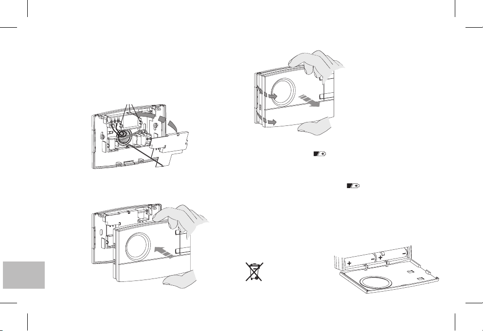
6 - FIJACIÓN O DESMONTAJE DEL CRONOTERMOSTATO DE LA BASE
Coloque la tapa cubrecables insertando la pestaña en la
ranura de la base y fíjela presionando ligeramente los
E
ganchos .
F
Para desmontar la tapa, haga palanca con un pequeño
destornillador en cada uno de los ganchos .
F
D
F
Para desmontar el
cronotermostato de la base
de pared, sujételo como se
indica en la figura y
extráigalo haciéndolo girar
hacia la derecha.
E
D
Enganche el cronotermostato a la base teniendo cuidado de
introducir correctamente los contactos y presione ligeramente
hasta que oiga que enganchan las pestañas de fijación.
ES
50
7- COLOCACIÓN O SUSTITUCIÓN DE LAS PILAS
La aparición delsímbolo indicaque laspilas se
están agotando; desdeeste momento dispone de30 díasaprox.
para cambiarlas.
Si las pilas no se sustituyen en el tiempo establecido la pantalla se
apagará visualizando sóloel símbolo fijo.
Todas las actividades de termorregulación se suspenden y las
configuraciones songrabadas paraser restablecidas con la instalación
de las nuevaspilas.
Cambie las pilas por 1,5 V tipo AA (LR6)
atención a los polos
ATENCIÓN: el tiempo disponible para la sustitución de las pilas,
sin perder los datos memorizados,
es de 1 minuto aproximadamente.
Deseche las pilas
agotadas en los
contenedores de
recogida especial.
parpadeante
pilas alcalinas prestando
.
Page 51
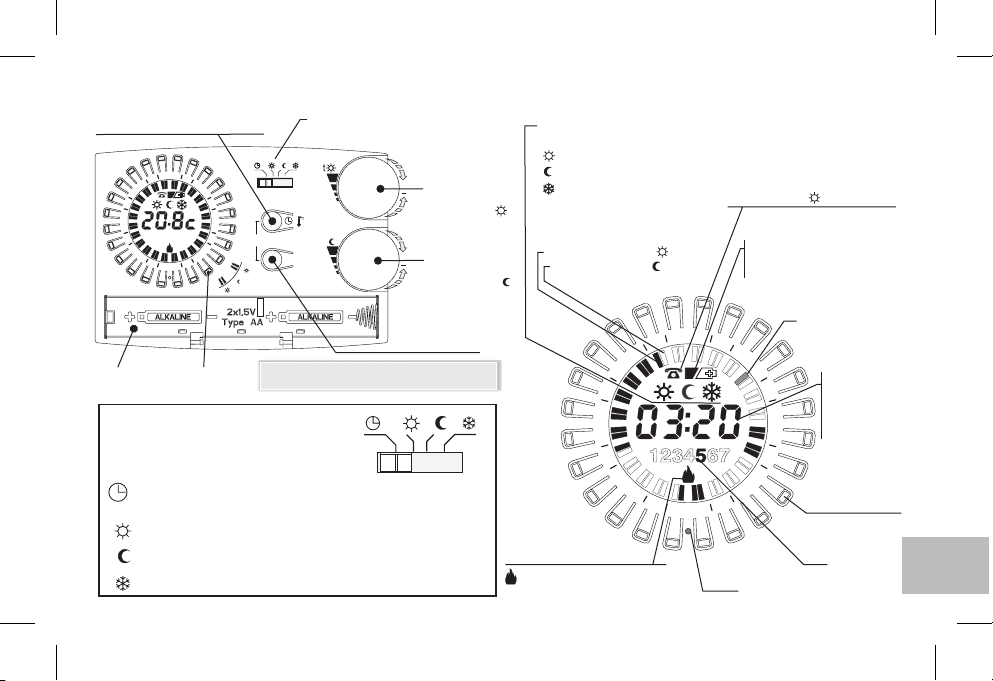
8 - VISTA GENERAL, LEYENDA DE LA PANTALLA Y FUNCIÓN DE LAS TECLAS
Tecla configuración: horas-minutos
o visual. Temperatura ambiente
4
2
21
8
1
15
Alojamiento
de las pilas
1234567
2
1
R
3
6
9
Teclas
“caballete”
t
t
t
TIPO DE FUNCIONAMIENTO
SELECCIONABLE MEDIANTE
CONMUTADOR
AUTOMÁTICO - regulables de 5 a 30 °C;Confort o Reducción
Siempre, Confort regulable de5a30°C(los 48 índices encendidos)
t
Siempre, Reducción regulable de5a30°C(los 48 índices apagados)
t
Siempre, Antihielo temperatura fijaa5°C(los 48 índices apagados)
t
según programación de los índices con las teclas caballete
Conmutador - modo de funcionamiento
(ver detalle en cuadro de abajo)
t
t
t
/
copy
Nota: lasotras funcionesespeciales de lasteclas
están descritasen losrespectivos apartados.
t
Day
(5 ÷ 30 °C)
Rueda reg.
+
temperatura de
Set confort
(5 ÷ 30 °C)
Rueda
+
temperatura de
Set reducción
(Ahorro)
Tecla de selección día
(mod. semanal)
t
reg.
t
ttt
Indicador estado carga
Visualización del tipo de
funcionamiento en curso:
Comfort
Reducción
Antihielo
Visualización del programa
seleccionado
Índice encendido = t confort
Índice apagado =t reducción
21
8
1
15
parpadea = relé activado
apagado = relé desactivado
Activación mediante el
programador telefónico
(con indicador parpadeante)
4
2
3
9
1
2
R
Reset
Indicador pilas:
- casi descargadas
- descargadas
(fijo)
Índice 1/2h corriente
parpadeante
Hora actual o
temperatura
ambiente registrada
/ set temperatura
6
de configuración
Teclas "caballete”
Día
(mod. semanal)
Ej. 5 = viernes
(parpadeante)
ES
51
Page 52
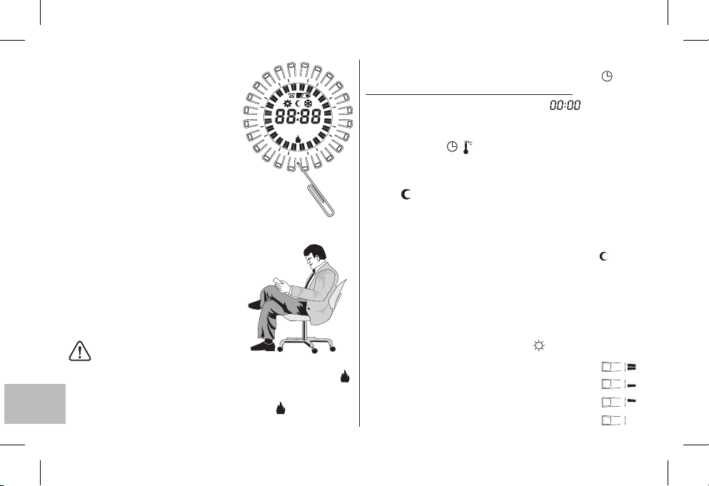
9 - REINICIALIZACIÓN
La primera vez que se enciendeRel cro-
notermostato o si presenta signos anormales oun funcionamiento incorrecto etc.,
inserte una varilla fina (máx 1 mm) en el
orificio de la corona entrelas teclas "caballete" y la tecla marcada con , y presione
brevemente.
todos los segmentosiluminados por unos
segundos comose observa enla figurade
al lado
borrarán restableciendo las configuraciones de fábrica (salvo las configuraciones
con los microinterruptores).
En la pantalla aparecerán
, ytodos losdatos dela memoriase
El cronotermostato estará listo para una nueva programación
(consulte el Capítulo 10).
4
2
21
8
1
15
123 5674
3
9
1
2
R
Programación facilitada
Todas las operaciones descritas en el
párrafo siguiente pueden efectuarse
antes de fijar el cronotermostato a la
base de la pared; esto le permitirá
efectuar la programación estando
cómodamente sentado.
¡ATENCIÓN!
Si la programacióndel cronotermostato se realizaantes de fijarloa la basede la
pared, puedeocurrir que alterminar la instalación,la indicaciónde la pantalla
(apagada o que parpadea) no corresponda al estado real del relé.
de 1minuto
se activará según la indicación presente en la pantalla (apagada o que
ES
parpadea).
52
a partirde la fijacióndel cronotermostato a labase depared, el relé
En menos
10 - PROGRAMACIÓN
Sitúe el conmutador en funcionamiento
IMPORTANTE: realizar l’operación de RESET
Al cabo de unos segundos la pantalla muestra que parpadea,
6
especifique la hora y minutos actuales como se describe a continuación.
Especificación de lahora ylos minutosactuales
Presione la tecla para programarla hora:
- manténgalapresionada pararegular lahora
/
- presiónelaa impulsospara regularminutos
(en el modelo diario, espere 5 segundos hasta que aparezca el
símbolo en la pantalla y el índice de la h que parpadea que
corresponde a la hora programada).
Ajuste del día actual (sólo para el modelo semanal)
La pantalla muestra el día que parpadea y corresponde al Lunes.
Con la tecla seleccione el día de la semana actual
Day
1
(espere 5 segundos hasta que aparezca el símbolo y el
índice de la media hora que parpadea y corresponde a la
hora programada).
Programación de la temperatura confort a los horarios deseados
Pulse y suelte
las teclas "caballete" dispuestas en círculo sobre
la pantalla, y que corresponden a la hora a la que se desea
activar la temperatura confort (nivel de temperatura
programado con el mando giratorio ), del siguiente modo:
°
1
- pulse ysuelte para activarla hora
°
2-
pulse y sueltepara activar laprimera mediahora
°
3-
pulse y sueltepara activar lasegunda media hora
°
4-
pulse y sueltepara desactivar lahora
AUTOMÁTICO .
½
t
Page 53
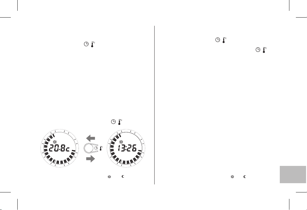
Copia del programaen variosdías (sólo parael modelo semanal)
Después dehaber efectuadola programacióndel día,es posible
copiarla en el día sucesivo
al mismo tiempo Day
Si desea establecer programas diferentes, seleccione el día
con la tecla y efectúe la programación presionando las
teclas caballete comose describe anteriormente.
Visualización delos programas establecidoscorrespondientes
a losdías dela semana
Pulse y sueltea impulsos latecla .
(Copy) presionando
las teclas y .
/
Day
(sólo paramodelo semanal).
Day
Nota: alterminar lasoperaciones deprogramación ovisualización, al
cabo de 5 segundos de la última acción en las teclas del cronotermostato se pone en marcha automáticamente (índice de la h
½
actual queparpadea).
En cualquier momento, se puede cambiar de ver la hora en la
pantalla a ver la temperatura ambiente (grados centígrados) y
viceversa, presionando brevementela tecla .
4
2
21
1
8
1
15
Visualización Set de temperatura t y/o configurado
ver apartado 11
3
6
3
9
2
1
1
/
4
2
21
8
1
/
15
3
6
3
9
2
21
1
MODIFICACIÓN DE LOSAJUSTES
Modificación de lahora actual
Mantener presionada la tecla hasta que parpadee la
hora actual.
Modifique la hora y/o minutos presionando la tecla como
/
/
se ha descrito anteriormente.
Modificación del díaactual (sólo parael modelosemanal)
Mantener presionada la tecla hasta que parpadee el
Day
número correspondiente al día actual.
Programe el nuevo día actual, presionando la tecla .
Day
Modificación de los programas establecidos
Modelo diario
Modifique el programa presionando directamente las teclas
"caballete" como seha descrito anteriormente.
Modelo semanal
Modifique el programa del día actual presionando
directamente las teclas "caballete" como se describe
anteriormente.
Para modificar el programa de los demás días de la semana
seleccione con la tecla el día deseado y presione
Day
directamente las teclas "caballete" como se describe
anteriormente.
Nota: al terminar las operaciones de modificación, al cabo de 5
segundos de la última acción en las teclas, el cronotermostato
se pone en marcha automáticamente (índice de la Vz h actual
que parpadea).
Modificación Set de temperatura t y/o configurado
ver apartado 11
ES
53
Page 54
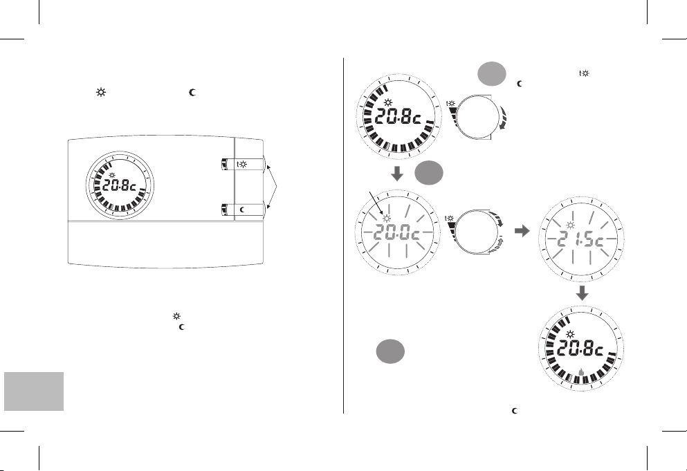
11 - VISIALIZACIÓN/MODIFICACIÓN DE LAS
TEMPERATURAS DE SET
(con las ruedas):
t CONFORT / t REDUCCIÓN
Generalmente la pantalla muestra la temperatura ambiente
registrada o lashoras y losminutos actuales.
4
2
21
3
8
1
15
6
3
9
1
2
t
Cuando se enciende el cronotermostato por primera vez, o
después de la orden de reinicio, los Set de temperatura
predefinidos en fábricason:
Set Temperaturadi confort
Set Temperatura direduccióntt
Cualquiera sea el estado operativo en que se encuentre el
cronotermostato, la visualización de los set actuales se realiza
girando brevemente la ruedahasta que el set comiencea parpadear,
después de5 seg.la pantallaregresa alfuncionamiento normal.
Si los setconfigurados no satisfacensus necesidades, sepueden
modificar en cualquier momento, de +5°C a +30 °C (de +41 °F a
ES
+86 °F), comose indica allado.
54
20.0 °C /68.0 °F(rueda superior)
=
17.0 °C/ 62.6 ( inferior)°F rueda
=
Se puedengirar
las ruedassin
abrir latapa.
Girar brevemente la
4
2
1
21
8
1
3
6
respectiva rueda( confort o
1°
t
reducción) para visualizar
el valor de la temperatura de
Set actuale iniciarel ajuste.
3
15
Indicación del set
que se modifica
21
8
1
15
Nota: si se configura un límite de temperatura (ver siguiente
apartado) el valor de set se puede aumentar hasta este límite
(bloqueo).
3°
Realizar el mismo procedimiento para configurar el Set de
temperatura de reduccióncon la rueda t
9
1
1
2
4
2
1
2
El Set correspondiente comienza a parpadear,
luego gire la rueda en sentido horario para
aumentar, o en sentido anti-horario para
2°
disminuir (durante el giro se obtiene una
modificación de0.1°C/0.1 °Fa la vez).
3
6
9
La temperaturafijada
será elnuevo Set de
referencia.
Pasados 5 seg. desde el último
giro de la rueda, la pantalla
regresa al estado normal de
funcionamiento:
4
2
21
+
8
1
15
1
2
4
2
1
21
8
1
3
15
1
1
2
3
6
9
3
6
9
Page 55
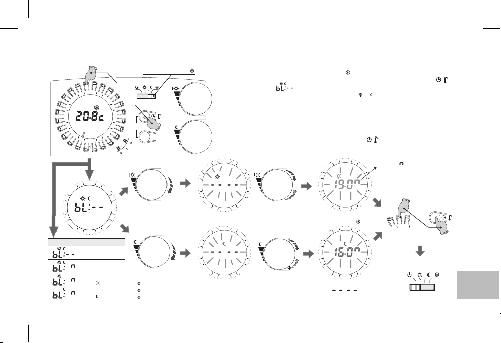
12 - LIMITACIÓN (BLOQUEO) DEL SET MÁX DE TEMPERATURA CONFORT Y/O REDUCCIÓN
En algunos casos de instalación del cronotermostato,por ejemplo en edificios públicos, hoteles, etc., es importante limitar el set de temperatura para evitar configuraciones equivocadas
por parte de personal no autorizado.
Tecla h23
tiempo por 4 s.
4
2
21
8
1
15
21
8
1
15
Visualizaciones posibles
3
12 45673
Ningún bloqueo
(configuración de fábrica)
Bloqueo en
ambos set
Bloqueo sólo
en el set confor t
Bloqueo sólo
en el set reducción
6
9
2
1
R
4
2
3
6
9
1
2
Mover el conmutador a t
Presionar al mismo
t
t
t
/
copy
t
t
t
y/o
Importante: si en 20 seg. no se gira una de las ruedas, el dispositivo sale automáticamente de la
programación de bloqueo sin grabar ninguna configuración yse coloca alfuncionamiento antihielo(t )
t
Notas:
para cancelar bloqueos configuradas con anterioridad, mover los set a:
El mando de reinicio cancela los posibles bloqueos configurados
t
Day
En la programación de base no se fija ninguna configuración de bloqueo.
Se puedenlimitar los valoresde Set (confort /reducción) detemperatura como sigue:
1
- Desplazarel conmutador almodo antihielo t (set fijoen+5°C nomodificable)
2
- Presionar al mismo tiempo por 4 seg. la tecla con la corona de la h23 y la tecla , la
pantalla visualiza :(ej. configuración defábrica= ningún bloqueo).
3
- Girar brevemente la ruedadel set correspondiente (t o t ) para visualizar elset actual.
4
- El set comienza a parpadear después de 3 seg. Configurar el bloqueo (limitación de
+5,1°C a +29,9°C girando la rueda en sentido horario para aumentar, o en sentido
antihorario para disminuir (durante el giro se obtieneuna modificación de 0,1°Ca la vez).
5
- Si sedesea, repetir las operaciones indicadas enlos puntos 3 y 4con la otramanopla.
6
- En 20seg. grabar laconfiguración y salir de laprogramación presionando almismo tiempo por 4seg. la tecla conla coronade lah23 y latecla .
7
- Desplazar elconmutador al modo defuncionamiento deseado.
4
2
21
8
1
15
21
8
1
15
3
+
8
6
9
2
1
4
2
3
t
6
9
2
1
1
+
8
1
21
15
21
15
/
4
2
2
1
4
2
2
1
El símbolo indica temperatura máx.
3
limitable, en °C o en °F
6
9
3
6
modo de funcionamiento deseado
9
/
Para grabar la configuración
y salir de la programación
42
Presionar al mismo
tiempo por 4 segundos
Desplazar el conmutador al
t
t
t
/
ES
55
Page 56
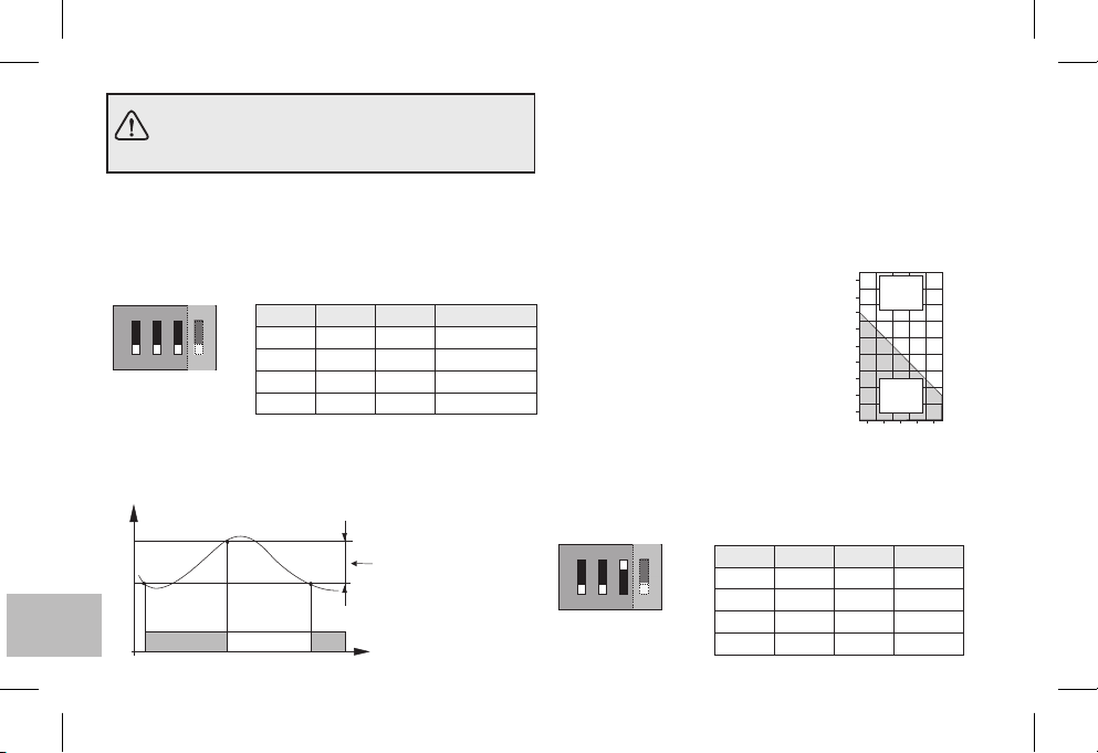
La configuración de los microinterruptores (Dipswitch) situados en la parte posterior del
cronotermostato, debe llevarla a cabo personal
cualificado.
13 - DIFERENCIAL DE TEMPERATURA
EI cronotermostato funciona en modo diferencial ON-OFF
(Dip 3 en posición OFF) con el valor del diferencial prefijado
en fábrica a (0,54 °F).0,3 °C
El valor del diferencial se puede modificar desplazando los
microinterruptores (Dip-switch), como se indica en la tabla.
ON
ON
ON
1
1
El valor del diferencial debe establecerse en base a la inercia
térmica de la instalación; se aconseja un valor bajo para
instalaciones con radiadores (por ejemplo en hierro fundido) y
un valor alto para instalaciones con fan-coils.
°C
ES
Temperatura medida
56
ON
Dip 1 Dip 2 Dip 3
OFF OFF OFF
32
32
4
OFF ON OFF
OFF
OFF
ON OFF OFF
ON ON OFF
Diferencial regulable
0,3 °C - 0,5 °C - 0,7 °C - 0,9 °C
(0,54 °F - 0,9 °F - 1,26 °F - 1.62 °F)
OffOn On
Tiempo
Diferencial
0,3 °C (0,54 °F)
0,5 °C (0,9 °F)
0,7 °C (1,26 °F)
0,9 °C (1,62 °F)
14 - FUNCIONAMIENTO PROPORCIONAL
Como alternativa al diferencial, la temperatura se puede regular
en modo proporcional (Dip 3 en la posición ON); este sistema
permite ahorrar energía y también previene el desgaste del
quemador, limitando sus encendidos. La duración de cada
encendido dependedel cicloprogramado yde ladiferencia entre
la temperatura programaday medida (verejemplo).
Ejemplo de programación t = 20 °C - Ciclo = 10 min
t = 20,5 °C Modo siempre apagado
t = 20,4 °C Modo 1 minON -9 min OFF
t = 20,3 °C Modo 2 minON -8 min OFF
t = 20,2 °C Modo 3 minON -7 min OFF
t = 20,1 °C Modo 4 minON -6 min OFF
t = 20,0 °C Modo 5 minON -5 min OFF
t = 19,9 °C Modo 6 minON -4 min OFF
t = 19,8 °C Modo 7 minON -3 min OFF
t = 19,7 °C Modo 8 minON -2 min OFF
t = 19,6 °C Modo 9 minON -1 min OFF
t = 19,5 °C Modo siempre encendido
La posición de los microinterruptores (Dip-switch), situados en la parte
posterior del cronotermostato, determina la duración del ciclo como se
indica en la tabla. Se aconseja un ciclo largo para instalaciones con
inercia térmica alta (radiadores de hierro fundido, sistemas de suelo) y
un ciclo breve para instalaciones con inercia térmica baja (fan- coil).
ON
ON
Dip 1 Dip 2 Dip 3
OFF OFF ON
4
32
1
OFF ON ON
OFF
ON OFF ON
ON ON ON
°C
20,8
Servicio
OFF
20,6
20,4
20,2
20,0
19,8
19,6
Servicio
19,4
ON
19,2
01024 6 8 Minutos
Duración ciclo
7 min
10 min
15 min
20 min
Page 57
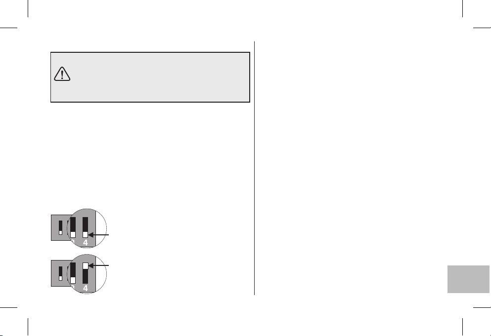
15 - ESCALA DE TEMPERATURA °C o °F
ATENCIÓN:
El cronotermostato viene programado de fábrica para
el funcionamiento en escala Celsius (grados
centígrados) pero el instalador o el usuario la
pueden modificar en grados Fahrenheit (°F).
El microinterruptor colocado alrespaldo del cronotermostato
se programaen fábrica en posición (grados centígrados).
Se puede desplazar a la posición la pantalla, después de
efectuar una operación de REINICIO muestra la temperatura
ambiente y losset en gradosFahrenheit (°F).
Pararegresar ala visualización engrados centígradosmover el
microinterruptor a la posición y realizar una operación
de REINICIO.
En ambos casos volver a programar el cronotermostato
comose indica enel capítulo 10.
ON
1
ON
1
4
OFF
ON:
4 OFF
OFF = escala en grados centígrados (°c)
432
(configuración de fábrica)
ON = escala en grados Fahrenheit (°F)
432
16 - ADVERTENCIAS
Lea atentamente este manual de instrucciones y
consérvelo para futurasconsultas.
Las figurascontenidas en estemanual muestran lapantalla
con laconfiguración de laescala de lastemperaturas en ºC
(grados Celsius).
Si en la pantalla aparece la temperatura ambiente
temperatura medida se encuentra por encima de los
límites de laescala.
Utilice solamente pilas alcalinas de 1,5V tipo AA LR6 (no
incluidas en la entrega), se puede perder la programación
efectuada debido aluso de pilasinadecuadas.
N.B.: el producto se ha probado y se garantizan sus
características con pilas alcalinas DURACELL o
ENERGIZER.
Importante:
años. De todas maneras se recomienda sustituirlas cada
24 meses para evitar que se agoten en períodos de
inactividad (ej. vacacionesnavideñas, etc.)
En caso de necesidad, limpie el cronotermostato con
un paño ligeramentehúmedo
El fabricante se reserva la facultad de introducir todas las
modificaciones técnicas y constructivas que crea
necesarias sin obligaciónde aviso.
, que parpadea, significa que00.0 °C o 50.0 °C la
la duraciónde laspilas puede ser superior a 2
ES
57
Page 58
SMALTIMENTODI VECCHIAPPARECCHIELETTRICI EDELETTRONICI (direttivaeuropea 2002/96/CE)
Questo simbolosul prodottoo sul suoimballo indicache questo prodottonon puòessere trattato comerifiuto domestico.
IT
Al contrario,dovrà essereportato ad unpunto diraccolta determinato peril riciclaggiodegli apparecchi elettricied elettronici,come ad esempio:
- puntivendita, nelcaso si acquistiun prodottonuovo simile aquello dasmaltire
- puntidi raccoltalocali (centri diraccolta rifiuti,centri locali diriciclaggio, ecc...).
AssicurandoVi che il prodotto sia smaltito correttamente, aiuterete a prevenire potenziali conseguenze negative per l'ambiente e la salute, che
potrebbero esserecausate daun inadeguato smaltimentodi questoprodotto.
Il riciclaggio dei materiali aiuterà a conservare le risorse naturali. Per informazioni più dettagliate riguardo il riciclaggio di questo prodotto,
contattate percortesia ilVs. ufficio locale,il Vs.servizio di smaltimentorifiuti domesticio il negoziodove aveteacquistato questo prodotto.
Attenzione: in alcuni paesi dell’Unione il prodotto non ricade nel campo di applicazione della legge nazionale di recepimento della direttiva
europea 2002/96/CE,e quindi non è inessi vigente alcun obbligodi raccoltadifferenziata a “finevita”.
DISPOSAL OFOLD ELECTRICAL& ELECTRONIC EQUIPMENT(EU directive2002/96/EC)
EN
FR
58
This symbolon theproduct or itspackaging toindicates that thisproduct shallnot be treatedas householdwaste.
Instead, itshall behanded over tothe applicablecollection point forthe recyclingof electrical andelectronic equipment,such as forexample:
- salespoints, incase you buya newand similar product
- localcollection points(waste collection centre,local recyclingcenter, etc...).
By ensuring this product isdisposed of correctly,you will help prevent potentialnegative consequence for the environmentand human health,
which couldotherwise becaused by inappropriatewaste handingof this product.
The recycling of materialswill help to conserve natural resources. Formore detailed information about recycling of thisproduct, please contact
your localcity office,your house holdwaste disposalservice or theshop whereyou purchased theproduct.
Attention: in some countries of the European Union, the product is not included in the field of application of the National Law that applies the
European Directive2002/96/EC andtherefore these countrieshave noobligation to carryout aseparate collection atthe “endof life” ofthe product.
TRAITEMENT DESAPPAREILS ÉLECTRIQUESET ÉLECTRONIQUESEN FIN DEVIE (directiveEU 2002/96/CE)
Ce symbole,apposé surle produit ousur sonemballage, indique quece produitne doit pasêtre traitéavec les déchetsménagers.
It doitêtre remisà un pointde collecteapproprié pour lerecyclage deséquipements électriques etélectroniques:
- dansle pointsde distribution encas d’achatd’un équipement équivalent.
- dansle pointsde collecte misà votredisposition localement (déchetterie,collecte sélective,etc...).
En s’assurant que ce produit est bienmis au rebut de manière appropriée, vous aiderez à prévenir les conséquences négatives potentielles pour
l’environnement et la santé humaine. Le recyclage des matériaux aidera à conserver les ressources naturelles. Pour toute informations
supplémentaire ausujet du recyclagede ce produit,vous pouvez contacter votremunicipalité, votre déchetterieou le magasinoù vous avezacheté
le produit.
Attention: dans certains pays de l’Union, tous les produits ne relèvent pas du champ d’application de la loi nationale de recyclage relative à la
directive europenne2002/96/CE etne font paspartie desproduits à récupéreren finde vie.
Page 59
DE
ES
ENTSORGUNG VONGEBRAUCHTEN ELEKTRISCHERUND ELEKTRONISCHER GERÄTEN (EU-Richtlinie2002/96/EG)
Dieses Symbol auf dem Produktoder seiner Verpackung weist darauf hin,dass dieses Produkt nichtals normalerHaushaltsabfall zu behandeln
ist, sondernan einerAnnahmestelle für dalRecycling vonelektrischen oder elektronischenGeräten abgegebenwerden muss, wiezum Beispiel:
- anden Verkaufsstellen,falls Sieein ähnliches Neugerätkaufen.
- anden örtlichenöffentlichen Sammelstellen (Wartstoffhof, Recyclingsammelstellen,usw...).
Durch Ihren Beitrag zum korrektenEntsorgen dieses Produktes schützen Siedie Umwelt und die Gesundheit Ihren Mitmenschen. Umwelt
werden durchfalsches Entsorgen gefährdet.Materialrecycling hilft denVerbrauchvon Rohstoffenzu verringern. WeitereInformation
Gesundheit
über das Recycling dieses Produktes erhalten Sie von Ihrem Gemeinde, den kommunalen Entsorgungsbetrieben oder dem Geschäft, in dem
Sie dasProdukt gekaufthaben.
Achtung: In einigen EU-Mitgliedsstaaten fällt das Produkt nicht unter den Anwendungsbereich des nationalen Gesetzes zur Umsetzung der
europäischen Richtlinie2002/96/EG. Dortbesteht keinerlei Verpflichtung zurgetrennten Sammlung von Elektro-und Elektronik-Altgeräten.
TRATAMIENTODE LOSAPARATOSELÉCTRICOS YELECTRÓNICOS EN FINALDE VIDA(directiva EU 2002/96/CE)
Ese símbolo,colado enel producto oen suembalaje, indica queese productono debe sertratado conlos desechos domésticos.
Debe depositarseen unpunto de colectaapropiado parael reciclaje delos equiposeléctricos y electrónicos:
- enlos puntosde distribución encaso decompra de unequipo equivalente.
- enlos puntosde colecta puestosa sudisposición localmente (vertedero,colecta selectiva,etc...).
Asegurándose queese producto sedesecha de maneraapropriada, ayudará aprevenir las potentialesconsecuencias negatives sobreel medio
ambiente y la salud humana. El reciclaje de los materiales ayudará a conservar los recursos naturales. Para cualquier información
complementaria al respecto de este producto, puede contactar con su ayuntamiento, el vertedero de su localidad, o el almacén dónde se
compró elproducto.
Atención: en algunos países de la Unión Europea, el producto no entra en el ámbito de aplicación de la ley nacional que acoge la directiva
europea 2002/96/CE;por lotanto, en talespaíses norige ninguna obligaciónde recogidadiferenciada al terminarla vidaútil del producto.
und
59
Page 60
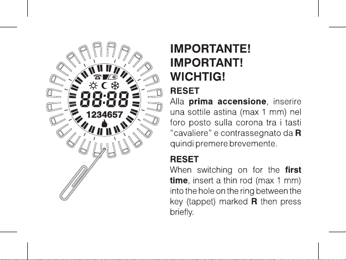
4
2
21
3
8
1
15
RESET
PE - DECRNN023 01/08
6
9
2
1
R
Page 61
 Loading...