

Page 1
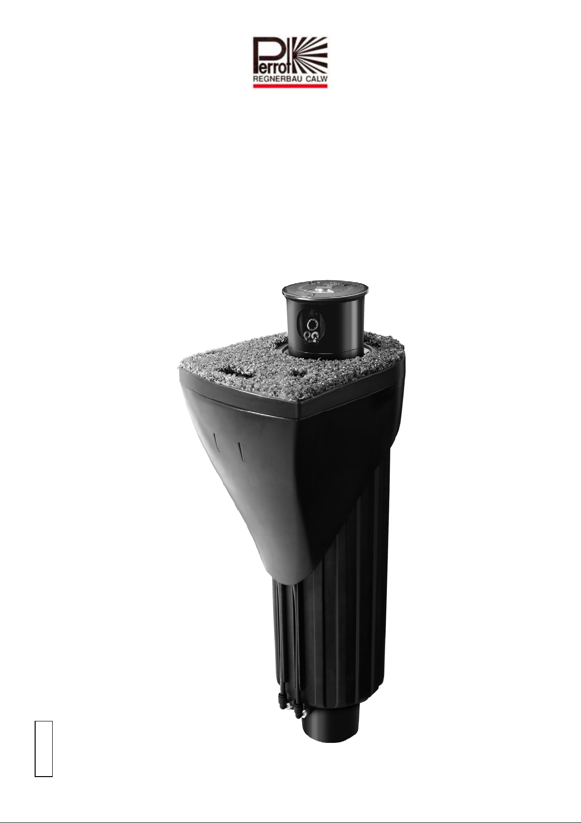
Bedienungsanleitung
Operating Manual
Versenkregner
Pop-up Sprinkler
Hydra L
PERROT
TDP051d+e bunt.doc Rev. 14.06.2010 Seite / Page 1 / 40
ZW01 99548
Perrot REGNERBAU CALW GmbH Industriestraße 19-27 / D-75382 Althengstett / Germany
Telefon : 0049-7051-162-0 / Fax : 0049-7051-162–133
Page 2

Inhaltsverzeichnis
1 SICHERHEIT............................................................................................................................................... 3
1.1 KENNZEICHNUNG VON HINWEISEN IN DER BETRIEBSANLEITUNG............................................................ 3
1.2 GEFAHREN BEI NICHTBEACHTUNG DER SICHERHEITSHINWEISE .............................................................. 3
2 BESCHREIBUNG ........................................................................................................................................ 4
3 INSTALLATION.......................................................................................................................................... 5
4 SONDERWERKZEUGE ............................................................................................................................. 5
5 INBETRIEBNAHME / WINTERFESTMACHUNG................................................................................6
5.1 INBETRIEBNAHME .................................................................................................................................... 6
5.2 WINTERFESTMACHUNG............................................................................................................................ 6
6 SEKTOR EINSTELLEN.............................................................................................................................. 7
7 DÜSE TAUSCHEN....................................................................................................................................... 9
7.1 EINSTELLEN DER EINLAUFDÜSE............................................................................................................. 11
7.2 EINBAU REGNEREINSATZ....................................................................................................................... 12
8 AUSBAU / EINBAU VENTILEINSATZ.................................................................................................. 13
8.1 AUSBAU DES VENTILS ........................................................................................................................... 13
8.2 AUSBAU GROBSIEB, NUR WENN VERSCHMUTZUNGEN ERKENNBAR....................................................... 14
8.3 EINBAU GROBSIEB................................................................................................................................. 15
8.4 EINBAU DES VENTILS............................................................................................................................. 15
8.5 EINBAU REGNEREINSATZ....................................................................................................................... 16
9 AUSBAU / EINBAU DER STEUEREINHEIT........................................................................................ 17
9.1 AUSBAU DER STEUEREINHEIT ................................................................................................................ 17
9.2 EINBAU DER STEUEREINHEIT ................................................................................................................. 18
10 AUSBAU / EINBAU DER HANDÖFFNUNG UND DRUCKREGULIEREINS Ä TZE.................... 18
10.1 AUSBAU DER HANDÖFFNUNG UND DRUCKREGULIEREINSÄTZE ............................................................. 18
10.2 EINBAU DER HANDÖFFNUNG UND DRUCKREGULIEREINSÄTZE .............................................................. 19
11 WARTUNG............................................................................................................................................. 19
12 BETRIEBSSTÖRUNGEN + BEHEBUNG........................................................................................... 20
12.1 FUNKTIONSSTÖRUNGEN......................................................................................................................... 20
TDP051d+e bunt.doc Rev. 14.06.2010 Seite / Page 2 / 40
Perrot REGNERBAU CALW GmbH Industriestraße 19-27 / D-75382 Althengstett / Germany
Telefon : 0049-7051-162-0 / Fax : 0049-7051-162–133
Page 3
1 Sicherheit
Diese Betriebs- und Sicherheitsanleitung enthält grundlegende Hinweise, die bei Montage
und Betrieb zu beachten sind. Daher ist diese Betriebsanleitung unbedingt vor Montage und
Inbetriebnahme vom Monteur sowie dem zuständigen Fachpersonal / Betreiber zu lesen.
Es sind nicht nur die in diesem Abschnitt ”Sicherheit” aufgeführten allgemeinen
Sicherheitshinweise zu beachten, sondern auch die in den anderen Abschnitten eingefügten
speziellen Sicherheitshinweise.
1.1 Kennzeichnung von Hinweisen in der Betriebsanleitung
Die in dieser Betriebsanleitung enthaltenen Sicherheitshinweise, deren Nichtbeachtung
Gefährdungen von Personen hervorrufen kann
sind mit dem allgemeinen Gefahrensymbol besonders gekennzeichnet.
Bei Sicherheitshinweisen, deren Nichtbeachtung Gefahren für den Regner und dessen
Funktion hervorrufen kann, ist das Wort eingefügt.
1.2 Gefahren bei Nichtbeachtung der Sicherheitshinweise
Die Nichtbeachtung der Sicherheitshinweise kann sowohl eine Gefährdung von Personen als
auch von Umwelt und Maschine zur Folge haben. Die Nichtbeachtung der
Sicherheitshinweise kann zum Verlust jeglicher Schadensansprüche führen.
ACHTUNG
TDP051d+e bunt.doc Rev. 14.06.2010 Seite / Page 3 / 40
Perrot REGNERBAU CALW GmbH Industriestraße 19-27 / D-75382 Althengstett / Germany
Telefon : 0049-7051-162-0 / Fax : 0049-7051-162–133
Page 4
2 Beschreibung
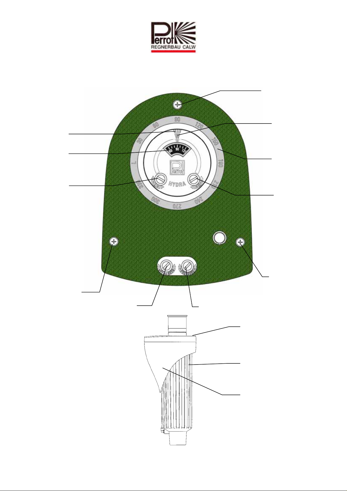
Richtung der
Düsenöffnung
Draufsicht
Deckelbefestingsschraube
Ablesepunkt
Anschlag rechts
Skalenrad
Einstell-
schraube
linker
Anschlag
Deckel-
befestings-
schraube
Handöffnung
Seitenansicht
Skala
Anschlag
rechts
Einstellschraube
rechter
Anschlag
Deckelbefestingsschraube
Druckregulierschraube
Gehäusedeckel
Führungsgehäuse
Schutzgehäuse
TDP051d+e bunt.doc Rev. 14.06.2010 Seite / Page 4 / 40
Perrot REGNERBAU CALW GmbH Industriestraße 19-27 / D-75382 Althengstett / Germany
Telefon : 0049-7051-162-0 / Fax : 0049-7051-162–133
Page 5
3 Installation
vor Montage der Regner die Leitung sorgfältig spülen
Anschlussgewinde mit Teflonband eindichten.
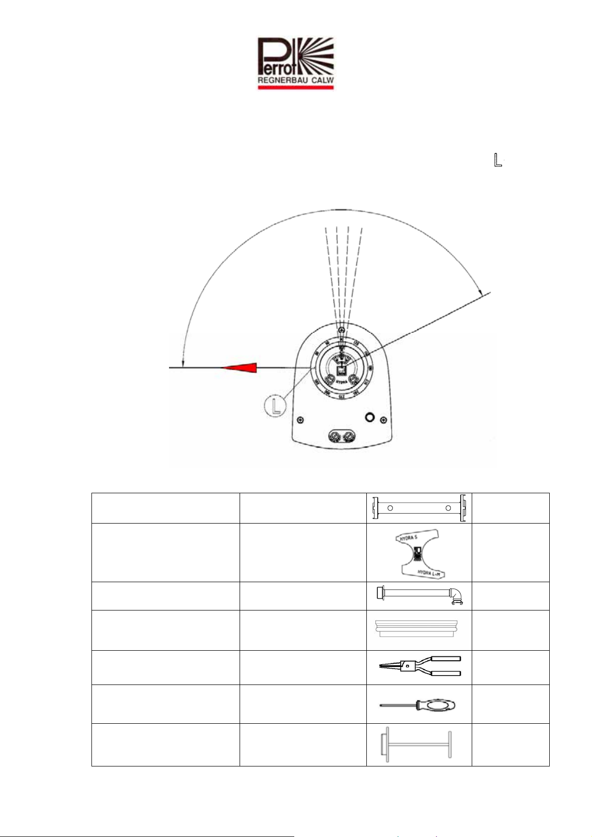
Beachte: Teilkreisregner müssen so ausgerichtet werden, dass die Markierung „ “
– in die Flucht von der linken Seite des Beregnungssektors zeigt.
Flucht
Linke Seite des Beregnungssektors
4 Sonderwerkzeuge
Schlüssel für Grobfilter Hydra L+S Grobfilter herausschrauben
Sicherungshalter für Regnerkopf
Hydra L/M/S
Spüleinsatz für Hydra L Leitung spülen
Adapter für Spüleinsatz
Halter für Düsenwechsel
Bei Hydra L nur mit
eingebautem Ventil
verwenden
RZG2 14130
RTV7 14031
RZB2 14134
RBA1 14136
Zange für Düsentausch Düse tauschen
Torx Schlüssel, TX 25 Für Schrauben am Deckel
Ausstecher Hydra L
TDP051d+e bunt.doc Rev. 14.06.2010 Seite / Page 5 / 40
Perrot REGNERBAU CALW GmbH Industriestraße 19-27 / D-75382 Althengstett / Germany
Telefon : 0049-7051-162-0 / Fax : 0049-7051-162–133
Regnergehäuse von Rasen
freistechen
ZB11 98276
ZB11 98297
RZG2 14144
Page 6
5 Inbetriebnahme / Winterfestmachung
5.1 Inbetriebnahme
(für Regner mit eingebautem Ventil)
a) Prüfen der elektrischen Funktion:
Bevor Wasserzufuhr zum Regner geöffnet wird, Spule mittels Steuergerät ansteuern.
Durch akustisches „Klicken“ an der Spule, lässt sich die korrekte elektrische Funktion
feststellen. (Klicken entsteht durch Anziehen des Ankers)
b) Sicherstellen, dass <Handöffnung> auf AUTO steht (Schraube für <Handöffnung>
links herum bis zum Anschlag drehen).
Bei dieser Stellung ist gewährleistet, dass der Regner nach Wasserzufuhr schließt,
wenn er stromlos ist.
c) Wasserzufuhr zum Ventil langsam öffnen, bis Betriebsdruck ansteht.
Möglicherweise öffnet der Regner kurz und sollte dann nach spätestens 30 sec.
selbständig schließen.
d) Nachdem die Wasserzufuhr geöffnet ist und der max. Betriebsdruck erreicht ist,
Regner und Anschluss auf Dichtheit prüfen.
e) Regner auf einwandfreie Funktion überprüfen:
Regner mit <Handöffnung> öffnen in dem die Schraube für <Handöffnung> in die
Zwischenstellung von AUTO und OFF gebracht wird (ca.1Umdrehung).
Regnerkopf steigt auf und beginnt sich zu drehen.
Nicht in Richtung der Düsenöffnung stehen!
Gewünschten Ausgangsdruck einstellen, indem die <Druckregulierschraube> rechts
(-) herum bis zum Anschlag gedreht wird (min. Druck). Nun ist der Ausgangsdruck
auf ca. 3 bar eingestellt. Wenn Sie die <Druckregulierschraube> eine volle
Umdrehung nach links (+) drehen, erhöht sich der Ausgangsdruck um 1 bar.
f) <Handöffnung> schließen und in Stellung AUTO bringen (siehe Punkt 5b).
Regner muss Wasserdurchfluss innerhalb 30 sec. abstellen.
g) Schritte e) und f) mehrmals wiederholen, bis eine fehlerfreie Funktion erreicht ist.
h) Korrekte Funktion durch elektrisches Ansteuern vom Steuergerät aus nochmals
überprüfen.
5.2 Winterfestmachung
Vor Eintritt der Frostperiode, muss der Regner entleert werden. Hierfür muss am
Leitungsnetz ein leistungsstarker Kompressor angeschlossen werden. Ventil am
Regner so lange geöffnet lassen, bis aus der Regnerdüse nur noch Luft austritt.
Regner verfügt über ein Entleerventil und kann auch herkömmlich über Schwerkraft
entleert werden.
Magnetspule mehrmals elektrisch ansteuern, damit das Restwasser aus dem
Spulenraum gedrückt wird. Es wird empfohlen, die Spule über die Winterzeit
2/Woche für ca. 1 Minute zu aktivieren.
TDP051d+e bunt.doc Rev. 14.06.2010 Seite / Page 6 / 40
Perrot REGNERBAU CALW GmbH Industriestraße 19-27 / D-75382 Althengstett / Germany
Telefon : 0049-7051-162-0 / Fax : 0049-7051-162–133
Page 7
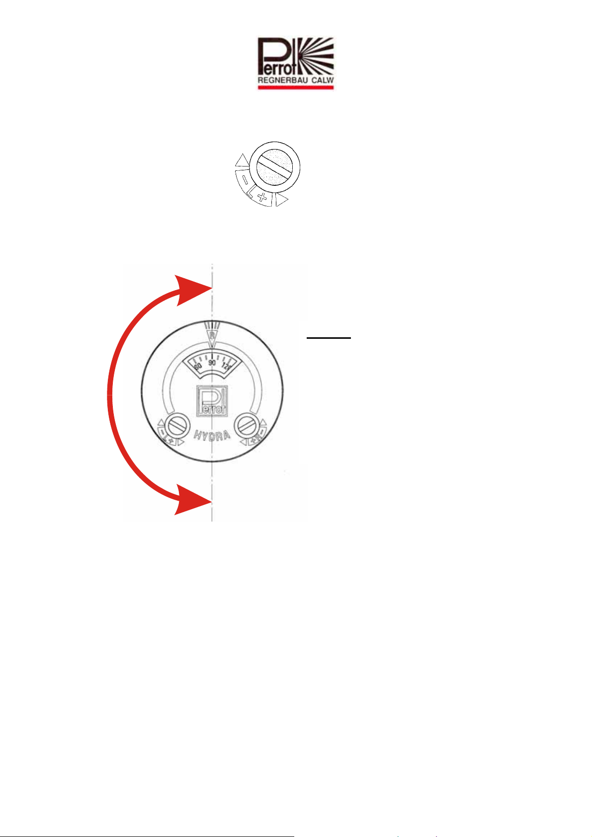
6 Sektor einstellen
(Nur bei Teilkreisregner)
Linke Anschlagseite mit einstellen.
Linker Anschlag lässt sich um +/- 90° verstellen
-
Beachte:
Bei einer vollen Umdrehung der
Stellschraube,
wird der Sektor Anschlag um 60°
verstellt
+
TDP051d+e bunt.doc Rev. 14.06.2010 Seite / Page 7 / 40
Perrot REGNERBAU CALW GmbH Industriestraße 19-27 / D-75382 Althengstett / Germany
Telefon : 0049-7051-162-0 / Fax : 0049-7051-162–133
Page 8
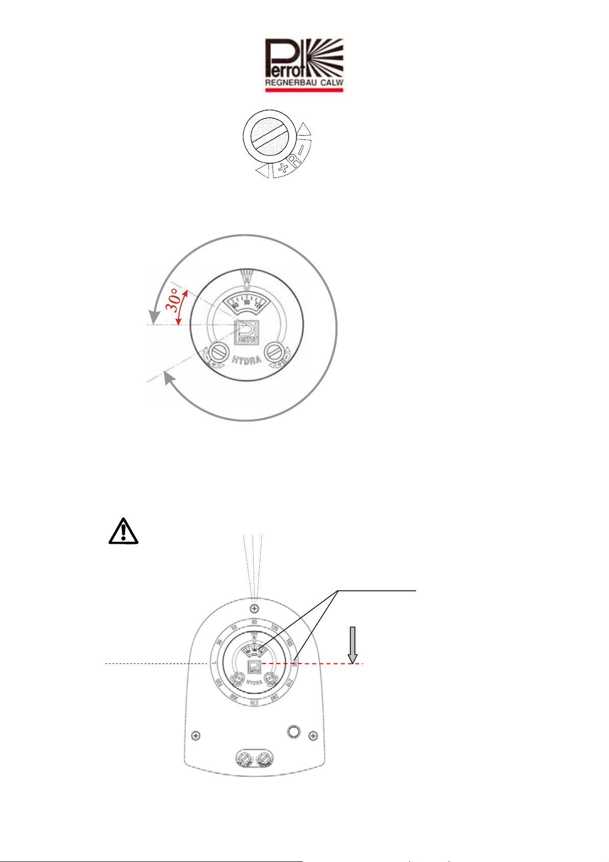
Rechte Anschlagseite mit einstellen.
Rechter Anschlag lässt
sich auf einen Sektor von 30° bis 330° einstellen.
330°
Beachte:
Bei einer vollen Umdrehung
der Stellschraube, wird der
Sektoranschlag um 60°
verstellt.
Hinweis: Der Wert auf dem Skalenrad zeigt an, wo der Regner gemäß
- Skala Anschlag rechts- umschaltet.
Hinweis: Um die Wartezeit beim Einstellen des Beregnungssektors zu verkürzen, kann
der Regnerkopf manuell in die momentane Drehrichtung vorgedreht werden.
NICHT ZURÜCKDREHEN!
Linker
Anschlag
Rechter
Anschlag
Ö rechter Anschlag ist an
der Stelle, wo diese
beiden Werte identisch
sind
TDP051d+e bunt.doc Rev. 14.06.2010 Seite / Page 8 / 40
Perrot REGNERBAU CALW GmbH Industriestraße 19-27 / D-75382 Althengstett / Germany
Telefon : 0049-7051-162-0 / Fax : 0049-7051-162–133
Page 9
7 Düse tauschen
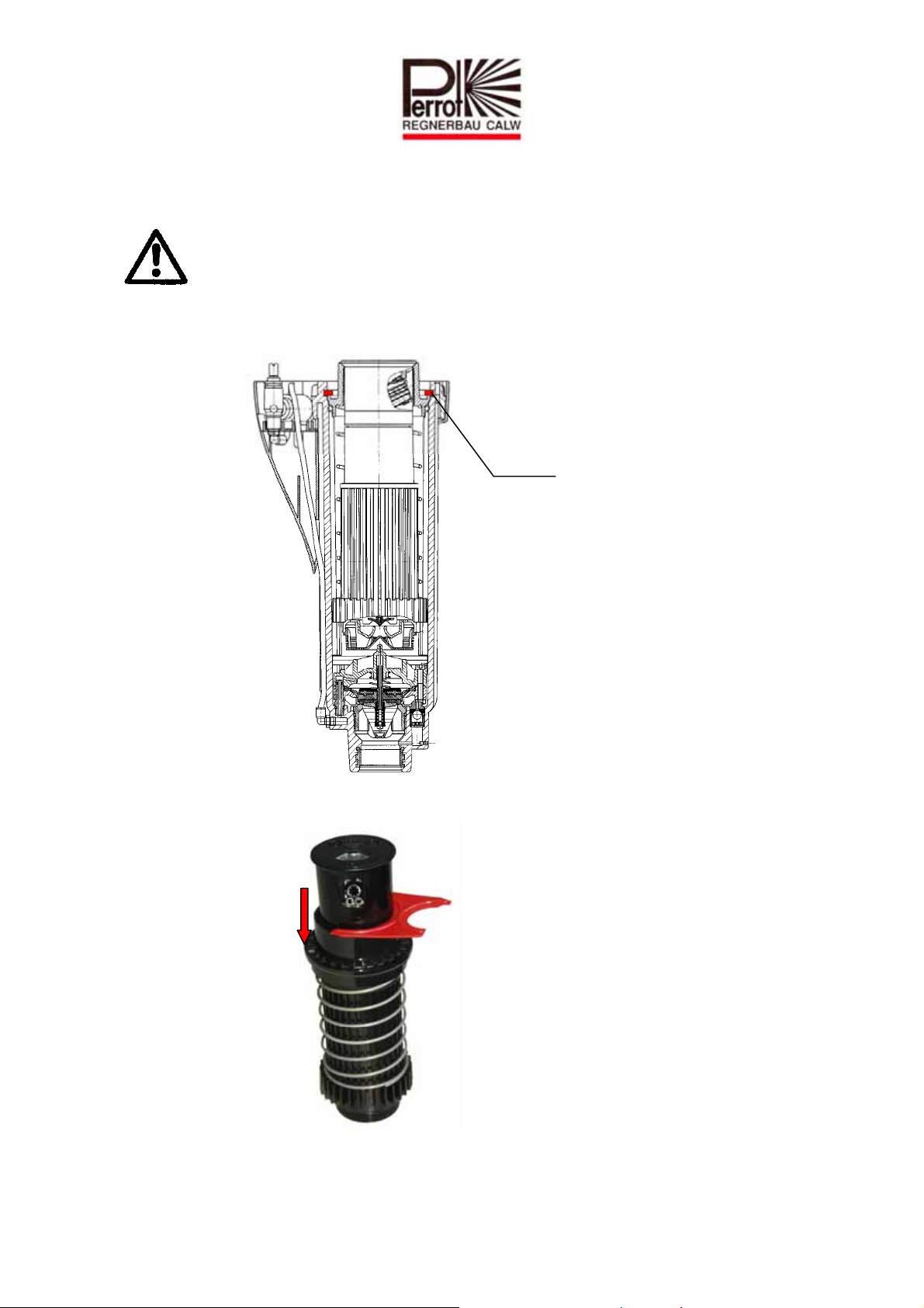
Sicherstellen, dass Regner drucklos ist.
Alle 3 Deckelbefestigungsschrauben lösen und Deckel abnehmen
Weißen Sicherungsring mit Schraubenzieher entfernen.
Sicherungsring
Regnereinsatz aus dem Gehäuse herausziehen
Flansch nach unten drücken und mit Sicherungshalter sichern
Regnerkopfdeckel abnehmen, indem Sie mit einem kleinen Schraubenzieher den
Deckel an der Aussparung hoch hebeln.
Düse mit Spitzzange nach links drehen und dann herausziehen
TDP051d+e bunt.doc Rev. 14.06.2010 Seite / Page 9 / 40
Perrot REGNERBAU CALW GmbH Industriestraße 19-27 / D-75382 Althengstett / Germany
Telefon : 0049-7051-162-0 / Fax : 0049-7051-162–133
Page 10
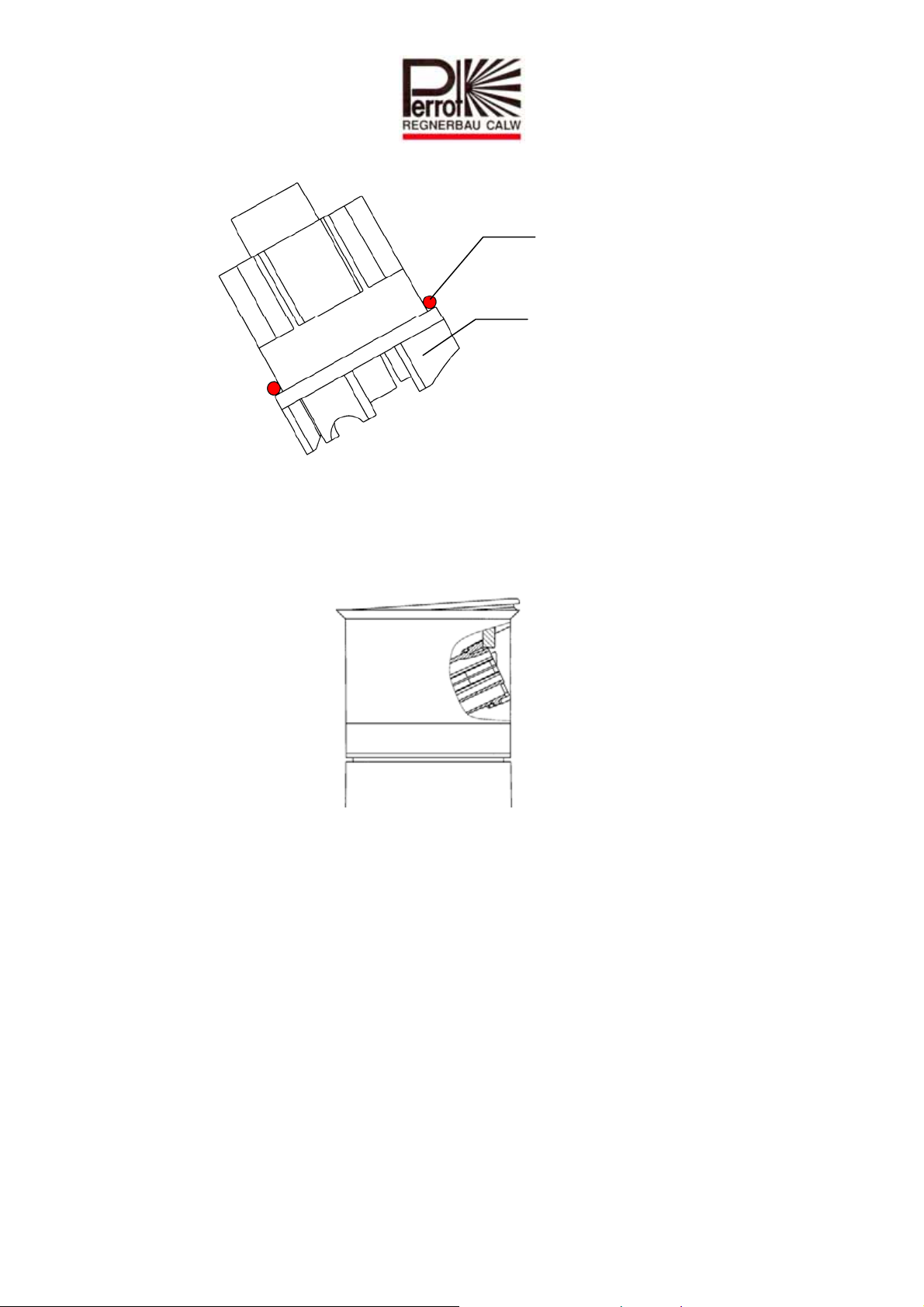
O-Ring auf die neue Düse stülpen
O-Ring
und in umgekehrter Vorgehensweise wieder im Regnerkopf montieren.
Deckel in Schnappverbindung von Regnerkopf einfügen indem er zuerst gegenüber
der Düsenseite bis zum Anschlag gedrückt wird und dann auf der Düsenseite vollends
einschnappt.
TDP051d+e bunt.doc Rev. 14.06.2010 Seite / Page 10 / 40
Perrot REGNERBAU CALW GmbH Industriestraße 19-27 / D-75382 Althengstett / Germany
Telefon : 0049-7051-162-0 / Fax : 0049-7051-162–133
Page 11
D
t
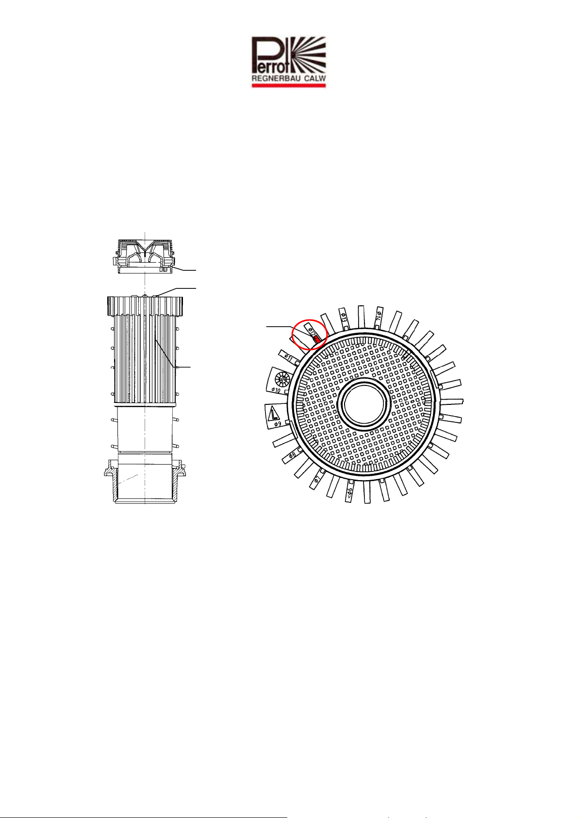
7.1 Einstellen der Einlaufdüse
Durch eine korrekte Einstellung der Einlaufdüse wird die empfohlene Drehgeschwindigkeit
eingehalten.
Einstellung wie folgt vornehmen:
Einlaufdüse und Sieb gemeinsam abnehmen indem die Einlaufdüse mit
Schraubenzieher an der Aussparung hochgehebelt wird.
Einlaufdüse wieder so auf Regnereinsatz schnappen, dass die verlängerte Rippe den
verwendeten Düsendurchmesser anzeigt.
Einlaufdüse
Turbine
Verlängerte
Rippe
Regnereinsatz
raufsich
Hinweis: Sollte eine höhere Drehgeschwindigkeit gewünscht werden, so muss die Rippe
auf einen kleineren Durchmesser zeigen, als die eingesetzte Düse ist.
TDP051d+e bunt.doc Rev. 14.06.2010 Seite / Page 11 / 40
Perrot REGNERBAU CALW GmbH Industriestraße 19-27 / D-75382 Althengstett / Germany
Telefon : 0049-7051-162-0 / Fax : 0049-7051-162–133
Page 12
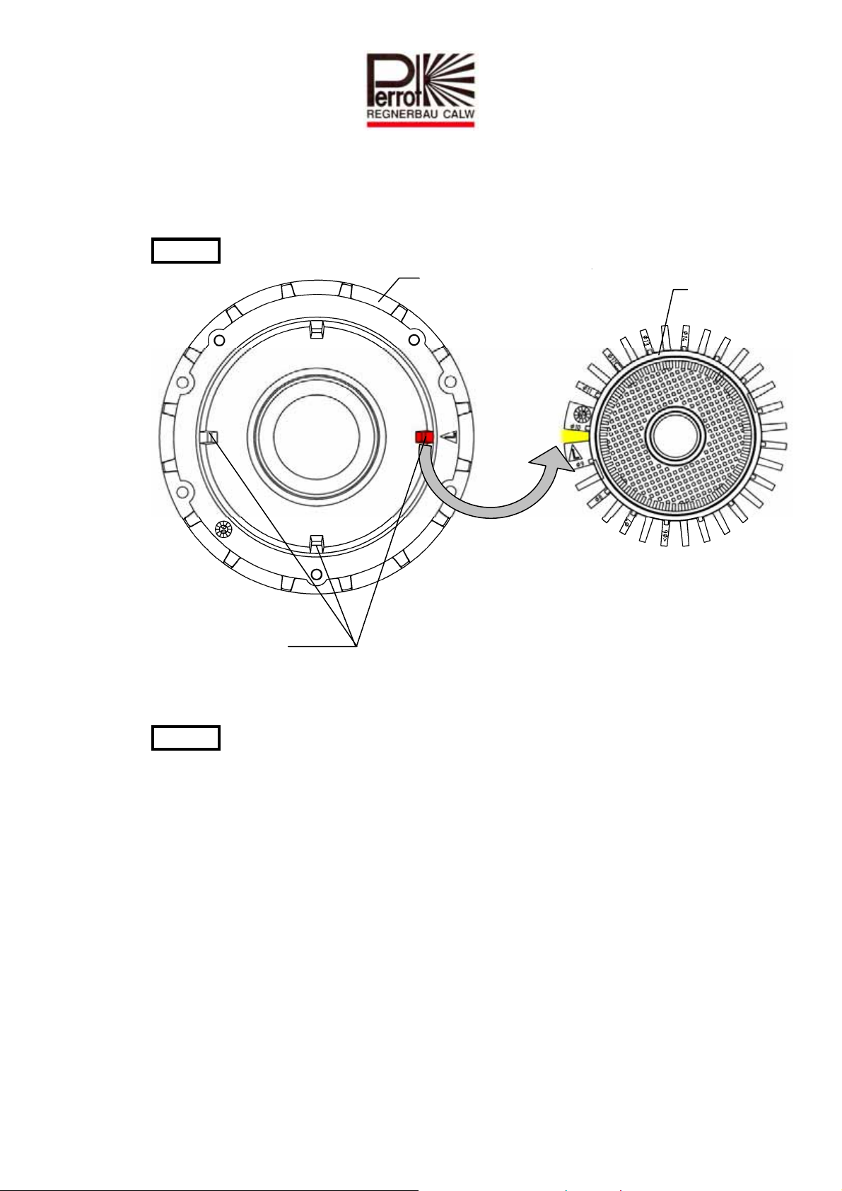
7.2 Einbau Regnereinsatz
O-Ring auf Flansch montieren und zur einfacheren Montage leicht einfetten
Regnereinsatz im Gehäuse montieren.
Achtung: Auf korrekte Orientierung achten.
Führungsgehäuse
Führungsrippen
Flansche bis zum Anschlag nach unten drücken
Sicherungsring montieren.
Achtung: Sicherungsring muss vollständig in die Nute eingefügt werden.
Gehäusedeckel mit allen drei Schrauben befestigen
Regner gemäß Punkt 5b-5e auf Funktion prüfen.
Regnereinsatz
TDP051d+e bunt.doc Rev. 14.06.2010 Seite / Page 12 / 40
Perrot REGNERBAU CALW GmbH Industriestraße 19-27 / D-75382 Althengstett / Germany
Telefon : 0049-7051-162-0 / Fax : 0049-7051-162–133
Page 13
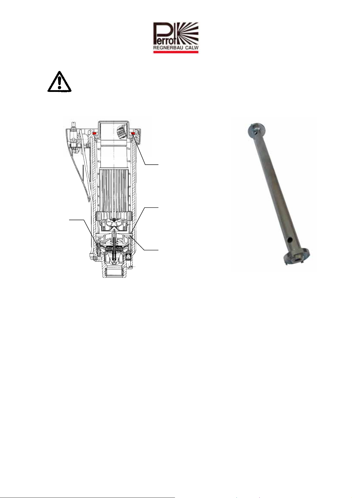
8 Ausbau / Einbau Ventileinsatz
Sicherstellen, dass Regner drucklos ist.
Alle 3 Deckelbefestigungsschrauben lösen und Deckel abnehmen
Weißen Sicherungsring mit Schraubenzieher entfernen.
Hohlschraube
Sicherungsring
Oberer
Sicherungsring
Unterer
Sicherungsring
Regnereinsatz aus dem Gehäuse herausziehen
8.1 Ausbau des Ventils
Oberen und Unteren Sicherungsring von Hand demontieren.
Ventilheber/Grobfilterschlüssel auf Zapfen von Ventileinsatz aufschrauben und
handfest anziehen.
Ventileinsatz komplett mit Ventilheber herausziehen und abschrauben. Ventileinsatz
wird nur noch durch O-Ring auf Hohlschraube gehalten.
TDP051d+e bunt.doc Rev. 14.06.2010 Seite / Page 13 / 40
Perrot REGNERBAU CALW GmbH Industriestraße 19-27 / D-75382 Althengstett / Germany
Telefon : 0049-7051-162-0 / Fax : 0049-7051-162–133
Page 14
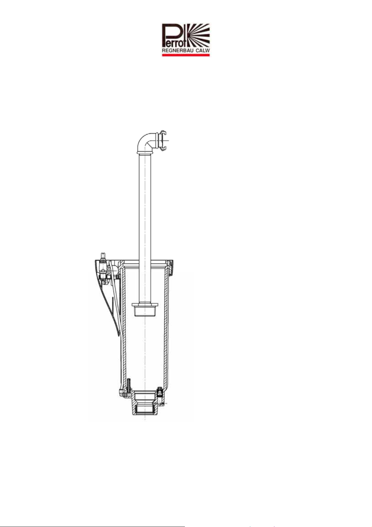
8.2 Ausbau Grobsieb, nur wenn Verschmutzungen erkennbar
Ventilheber/Grobfilterschlüssel in Nuten des Grobsiebs einstecken und herausdrehen.
Spüleinsatz einschrauben und Regner gründlich durchspülen.
TDP051d+e bunt.doc Rev. 14.06.2010 Seite / Page 14 / 40
Perrot REGNERBAU CALW GmbH Industriestraße 19-27 / D-75382 Althengstett / Germany
Telefon : 0049-7051-162-0 / Fax : 0049-7051-162–133
Page 15
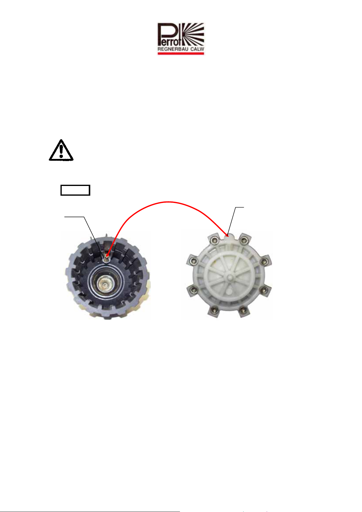
8.3 Einbau Grobsieb
Spüleinsatz herausdrehen.
Sicherstellen, dass Gewinde und O-Ring sauber sind.
O-Ring leicht mit säurefreiem Fett einfetten.
Grobsiebs ansetzen und mit Grobfilterschlüssel handfest anziehen.
8.4 Einbau des Ventils
Überprüfen Sie vor Montage des Ventils den Ventileinsatz besonders im
Bereich des Ventilsitzes auf Verschmutzungen oder Beschädigungen!
Gereinigten oder neuen Ventileinsatz wieder auf den Ventilheber aufschrauben und in
Regnergehäuse montieren.
Achtung: Auf korrekte Einbaulage achten
Hohlschraube
Aufnahme für
Hohlschraube
TDP051d+e bunt.doc Rev. 14.06.2010 Seite / Page 15 / 40
Perrot REGNERBAU CALW GmbH Industriestraße 19-27 / D-75382 Althengstett / Germany
Telefon : 0049-7051-162-0 / Fax : 0049-7051-162–133
Page 16
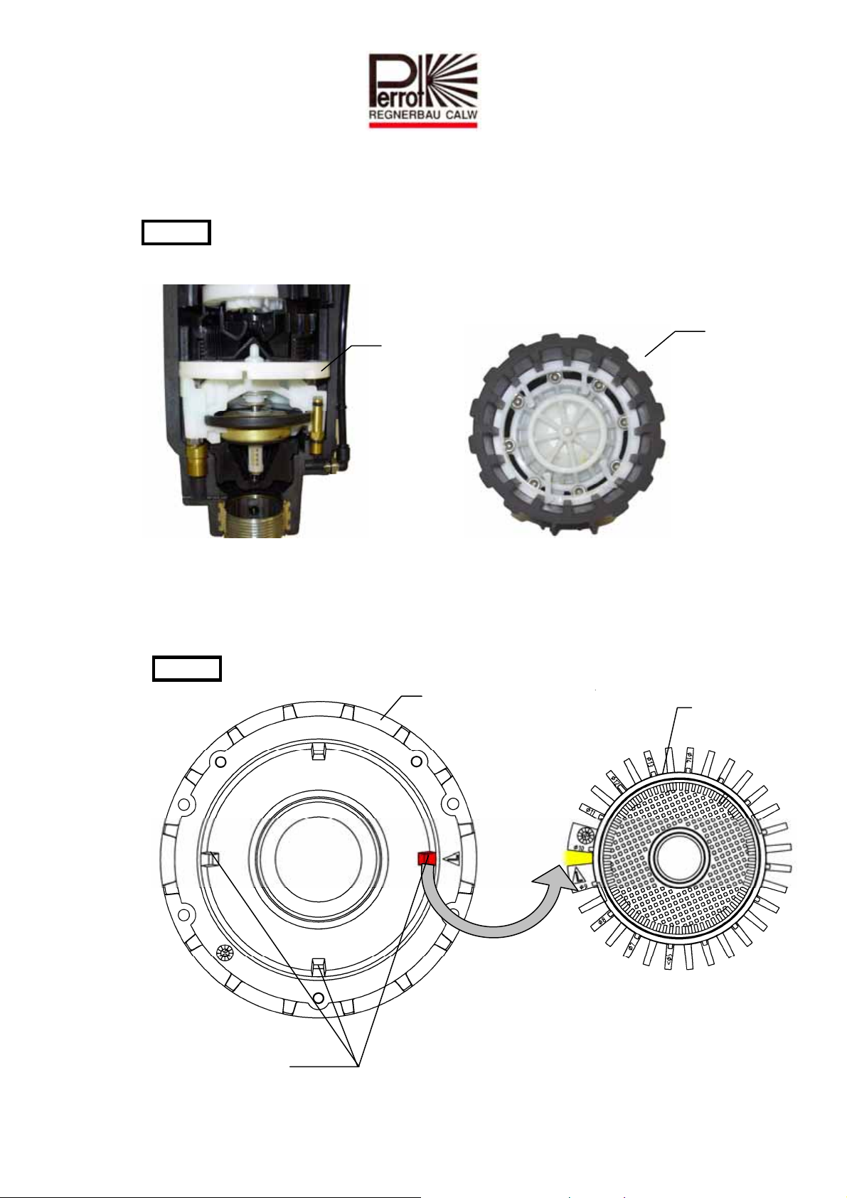
Unteren Sicherungsring mit Höcker nach oben einsetzen, oberen Sicherungsring um
180° gedreht mit Höcker nach unten montieren.
Achtung: Sicherungsringe müssen vollständig in die Nut eingeführt sein.
Sicherungsring
8.5 Einbau Regnereinsatz
O-Ring auf Flansch montieren und zur einfacheren Montage leicht einfetten
Regnereinsatz im Gehäuse montieren.
Achtung: Auf korrekte Orientierung achten.
Sicherungsring
Führungsgehäuse
Führungsrippen
TDP051d+e bunt.doc Rev. 14.06.2010 Seite / Page 16 / 40
Perrot REGNERBAU CALW GmbH Industriestraße 19-27 / D-75382 Althengstett / Germany
Telefon : 0049-7051-162-0 / Fax : 0049-7051-162–133
Regnereinsatz
Page 17
Flansche bis zum Anschlag nach unten drücken
Sicherungsring montieren.
Achtung: Sicherungsring muss vollständig in die Nute eingefügt werden.
Gehäusedeckel mit allen drei Schrauben befestigen
Regner gemäß Punkt 5b-5e auf Funktion prüfen.
9 Ausbau / Einbau der Steuereinheit
Sicherstellen, dass Regner drucklos ist.
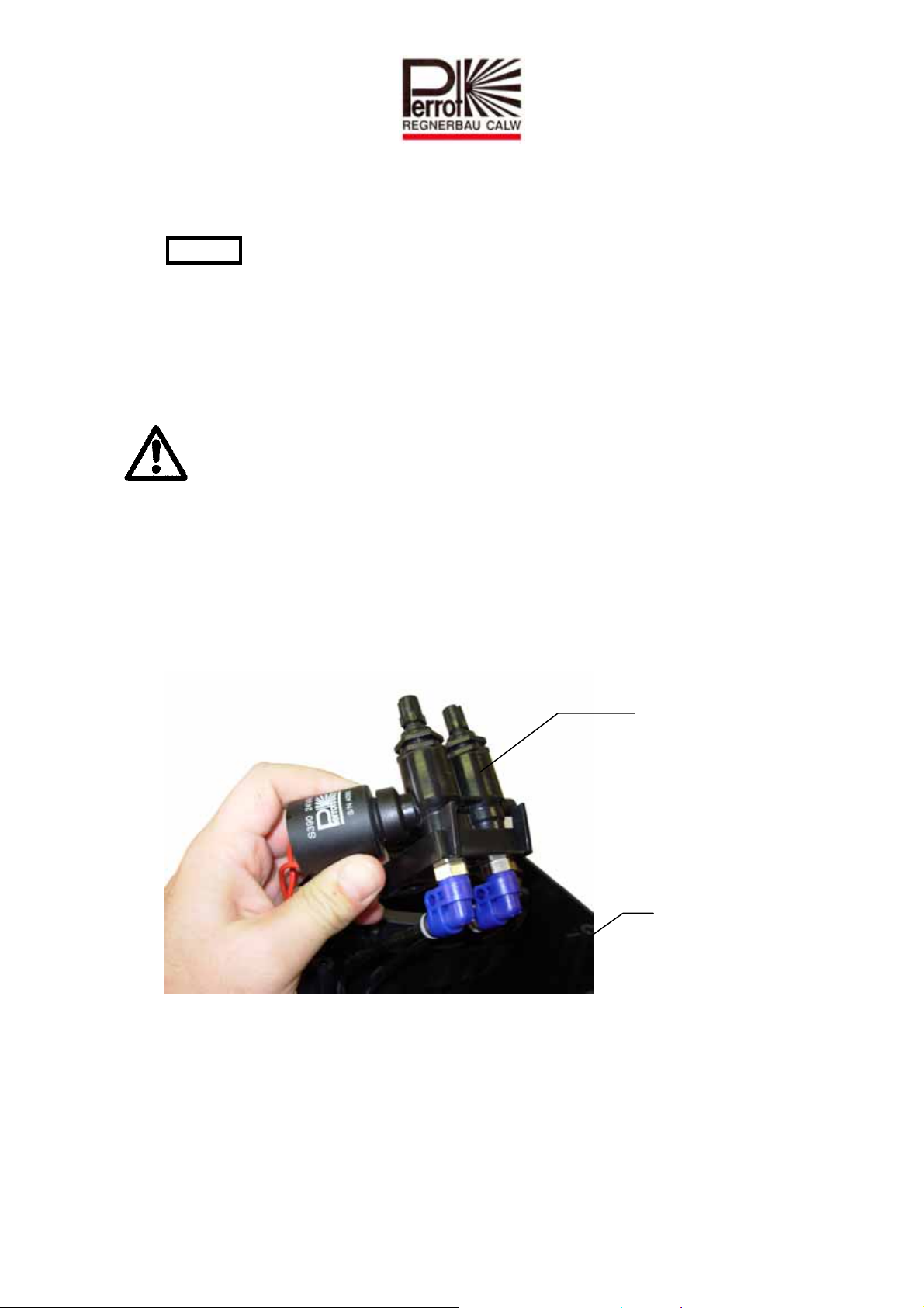
9.1 Ausbau der Steuereinheit
Alle 3 Deckelbefestigungsschrauben lösen und Deckel abnehmen.
Steuereinheit aus Schutzgehäuse herausklipsen und anheben.
Spule herausdrehen
Beim Austausch der Steuereinheit, Schläuche so dicht wie möglich an der Tülle der
Steuereinheit abschneiden.
Steuereinheit
Regner
TDP051d+e bunt.doc Rev. 14.06.2010 Seite / Page 17 / 40
Perrot REGNERBAU CALW GmbH Industriestraße 19-27 / D-75382 Althengstett / Germany
Telefon : 0049-7051-162-0 / Fax : 0049-7051-162–133
Page 18
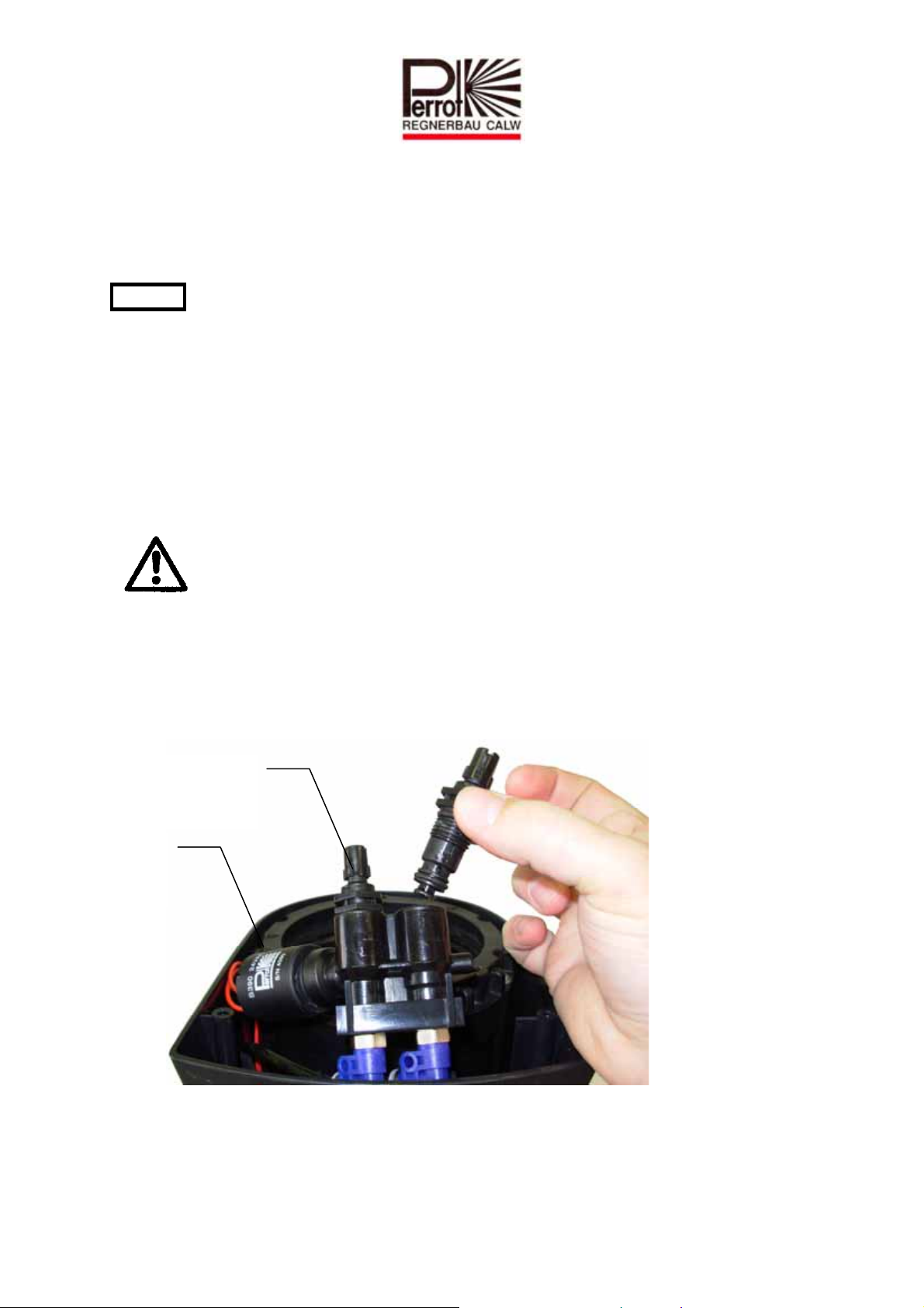
9.2 Einbau der Steuereinheit
Bei Ersatzteilbezug wird die Steuereinheit mit Steckanschlüssen geliefert. Schläuche
in Stecktüllen bis zum Anschlag eindrücken und sicherstellen dass Montagering
wieder zurückspringt.
Achtung: Bitte beachten Sie dass die Schläuche in der richtigen Pos. montiert werden,
ansonsten haben Sie keine Funktion des Regners.
Spule einschrauben
Steuereinheit in Schutzgehäuse klipsen.
Gehäusedeckel mit allen drei Schrauben befestigen
Regner gemäß Punkt 5b-5e auf Funktion prüfen.
10 Ausbau / Einbau der Handöffnung und Druckreguliereinsätze
Sicherstellen, dass Regner drucklos ist.
10.1 Ausbau der Handöffnung und Druckreguliereinsätze
Alle 3 Deckelbefestigungsschrauben lösen und Deckel abnehmen.
Steuereinheit aus Schutzgehäuse herausklipsen und anheben.
Handöffnung und Druckregler mit Gabelschlüssel SW19 herausdrehen.
Steuereinheit
Spule
TDP051d+e bunt.doc Rev. 14.06.2010 Seite / Page 18 / 40
Perrot REGNERBAU CALW GmbH Industriestraße 19-27 / D-75382 Althengstett / Germany
Telefon : 0049-7051-162-0 / Fax : 0049-7051-162–133
Page 19

10.2 Einbau der Handöffnung und Druckreguliereinsätze
Handöffnung in Auto und Druckregler bzw. in min. (-) Stellung bringen,
(bis Anschlag nach links drehen) und mit Gabelschlüssel SW19 einschrauben.
Steuereinheit in Schutzgehäuse klipsen.
Gehäusedeckel mit allen drei Schrauben befestigen
Regner gemäß Punkt 5b-5e auf Funktion prüfen.
Handöffnung bzw. Druckregler auf gewünschte Position stellen
11 Wartung
Regnergehäuse von überwachsendem Gras freistechen. Diese Arbeiten sollten
Sinnvollerweise vor der Frühjahrsinbetriebnahme mit dem Freistecher
(Bestellnummer siehe Kapitel 4) durchgeführt werden.
TDP051d+e bunt.doc Rev. 14.06.2010 Seite / Page 19 / 40
Perrot REGNERBAU CALW GmbH Industriestraße 19-27 / D-75382 Althengstett / Germany
Telefon : 0049-7051-162-0 / Fax : 0049-7051-162–133
Page 20
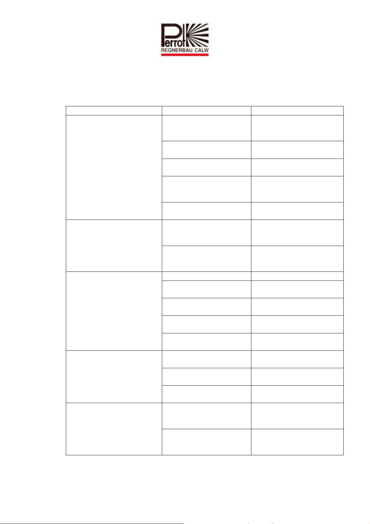
12 Betriebsstörungen + Behebung
12.1 Funktionsstörungen
Problem Ursache Behebung
Ventil öffnet/schließt nur mit
Handöffnung, jedoch nicht auf
elektrisches Signal
Schraube für
<Handöffnung> ist in
Stellung OFF
Kern in der Spule klemmt Spule ausbauen und Kern
Keine oder zu geringe
Versorgungsspannung
Spule defekt Spulenwiderstand prüfen
Entlastungskanal von Spule
verstopft
Ventil öffnet auch mit der
Handöffnung nicht
Steuerwasser- oder
Entlastungsbohrung
verstopft
Kein oder zu geringer
Druck auf der
Versorgungsleitung
Ventil schließt nicht
Spulensitz verschmutzt Spulensitz reinigen
Schmutzteile zwischen
Ventilsitz und Dichtteller
Membrane defekt Ventil ausbauen und
Zu wenig Druckabfall am
Ventil
Steuerwasserfilter
verschmutzt
Drehgeschwindigkeit zu
gering / zu hoch oder dreht
gar nicht
Einlaufdüse falsch
eingestellt (siehe Kap.7)
Turbine blockiert durch
Steine und Schmutzteile
Einlaufdüse oder Sieb
haben sich gelöst
Ausgangsdruck an
Regnerdüse oder Wurfweite
zu gering
Steine und Schmutzteile
verhindern ungestörten
Wasserdurchfluss
Druckregler auf min (-)
Stellung
Wir behalten uns Änderungen nach dem Stand der Technik auch ohne besondere Ankündigung vor.
Schraube links herum bis
zum Anschlag
reinigen
Versorgungsspannung von
24 VAC herstellen
(Soll ca. 35 Ohm) evtl. Spule
tauschen
Kanal reinigen
Steuerwasser- /
Entlastungsbohrung reinigen
Druckversorgung herstellen
Ventilsitz und Dichtteller
reinigen
Membrane wechseln
<Druckregulierschraube>
zudrehen
Steuerwasserfilter reinigen
Einlaufdüse auf richtigen
Düsendurchmesser einstellen
Turbine reinigen
Teile wieder zusammen
klipsen
Ventil reinigen und Regner
spülen
Druckregelschraube links
herum, in Richtung(+)
drehen
TDP051d+e bunt.doc Rev. 14.06.2010 Seite / Page 20 / 40
Perrot REGNERBAU CALW GmbH Industriestraße 19-27 / D-75382 Althengstett / Germany
Telefon : 0049-7051-162-0 / Fax : 0049-7051-162–133
Page 21

Contents
1 SAFETY ....................................................................................................................................................... 22
1.1 HOW INSTRUCTIONS ARE MARKED IN THIS MANUAL ................................................................................... 22
1.2 HAZARDS OF IGNORING SAFETY INSTRUCTIONS ......................................................................................... 22
2 DESCRIPTION............................................................................................................................................ 23
3 INSTALLATION.......................................................................................................................................... 24
4 SPECIAL TOOLS........................................................................................................................................ 24
5 COMMISSIONING / PREPARING FOR WINTER.................................................................................. 25
5.1 COMMISSIONING ..................................................................................................................................... 25
5.2 PREPARING FOR WINTER.......................................................................................................................... 25
6 SETTING IRRIGATION SECTOR ............................................................................................................ 26
7 REPLACING THE NOZZLE...................................................................................................................... 28
7.1 ADJUSTING THE INLET NOZZLE................................................................................................................. 30
7.2 FITTING THE SPRINKLER INSERT............................................................................................................... 31
8 VALVE INSERT REMOVAL / INSTALLATION...................................................................................... 32
8.1 TAKING OUT THE VALVE........................................................................................................................... 32
8.2 TAKING OUT THE COARSE FILTER – ONLY IF SEEN TO BE DIRTY .................................................................. 33
8.3 FITTING COARSE FILTER .......................................................................................................................... 34
8.4 FITTING THE VALVE................................................................................................................................. 34
8.5 FITTING THE SPRINKLER INSERT............................................................................................................... 35
9 CONTROL UNIT REMOVAL / INSTALLATION..................................................................................... 36
9.1 TAKING OUT THE CONTROL UNIT.............................................................................................................. 36
9.2 FITTING THE CONTROL UNIT .................................................................................................................... 37
10 REMOVAL / FITTING OF MANUAL OPENING AND PRESSURE REGULATING INSERTS..... 37
10.1 REMOVAL OF MANUAL OPENING AND PRESSURE REGULATING INSERTS ...................................................... 37
10.2 FITTING MANUAL OPENING AND PRESSURE REGULATING INSERTS.............................................................. 38
11 MAINTENANCE.....................................................................................................................................38
12 TROUBLESHOOTING........................................................................................................................... 39
12.1 MALFUNCTIONS ...................................................................................................................................... 39
TDP051d+e bunt.doc Rev. 14.06.2010 Seite / Page 21 / 40
Perrot REGNERBAU CALW GmbH Industriestraße 19-27 / D-75382 Althengstett / Germany
Telefon : 0049-7051-162-0 / Fax : 0049-7051-162–133
Page 22
1 Safety
This operating & safety manual contains fundamental advice to be heeded during
installation and operation. It is therefore imperative that the fitter and relevant engineer /
operator read this manual thoroughly prior to commissioning and operation.
Please follow both the general safety instructions specified in this ‘safety’ section and the
specific safety warnings included in other sections.
1.1 How instructions are marked in this manual
Safety instructions that, if ignored, could endanger human life or limb are marked with the
general "danger" symbol:
"Warning" is printed next to instructions that, if ignored, could be hazardous to the sprinkler
and its operation.
1.2 Hazards of ignoring safety instructions
Failing to heed the safety instructions may result in danger to life and limb, harm to the
environment and/or damage to the device. Failing to heed the safety instructions may lead to
the loss of any right to claim compensation.
WARNING
TDP051d+e bunt.doc Rev. 14.06.2010 Seite / Page 22 / 40
Perrot REGNERBAU CALW GmbH Industriestraße 19-27 / D-75382 Althengstett / Germany
Telefon : 0049-7051-162-0 / Fax : 0049-7051-162–133
Page 23
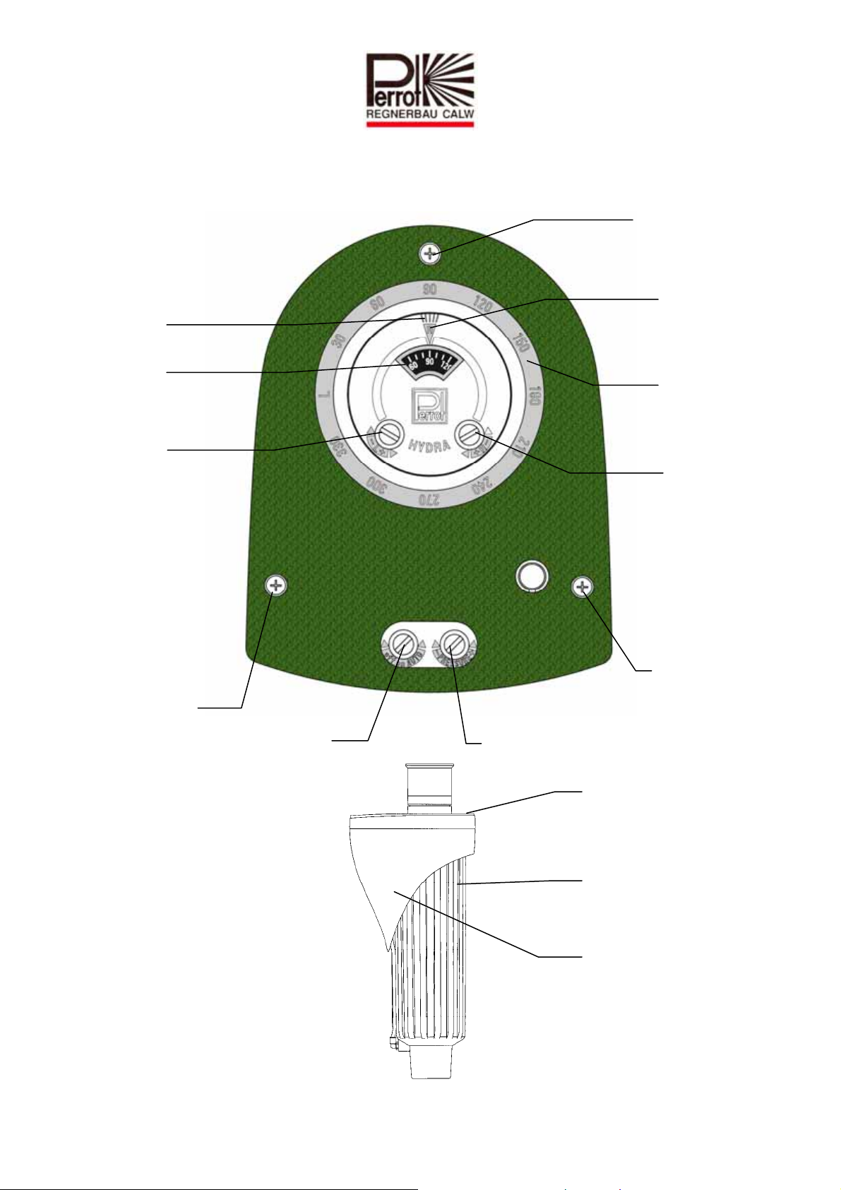
2 Description
Direction of
nozzle opening
View from above
Cover
securing
screw
Read-out point
Right stop
position
Rotary scale
Left stop
position
adjuster
screw
securing
Cover
screw
Manual opening
Side view
Scale
Right stop
position
Right stop
position
adjuster
screw
Cover
securing
screw
Pressure
regulator screw
Housing cover
Guide housing
Protective housing
TDP051d+e bunt.doc Rev. 14.06.2010 Seite / Page 23 / 40
Perrot REGNERBAU CALW GmbH Industriestraße 19-27 / D-75382 Althengstett / Germany
Telefon : 0049-7051-162-0 / Fax : 0049-7051-162–133
Page 24
3 Installation
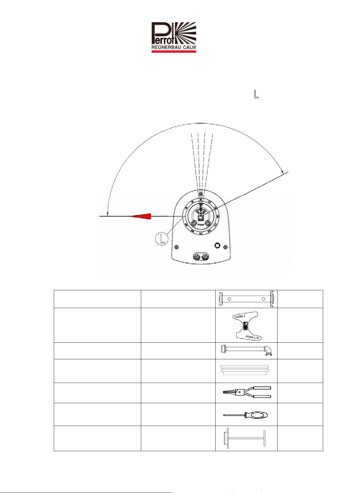
Thoroughly flush the pipeline before installing the sprinkler
Seal connecting thread with Teflon tape.
Note: Part-circle sprinklers must be set up in such a way that the ‘ ’ mark
is aligned in a straight line from the left side of the irrigation sector.
Alignment
Left side of irrigation sector
4 Special tools
Key for coarse filter Hydra L+S Disassembly of coarse filter
Retainer for sprinkler head
Hydra L/M/S
Flushing equipment Hydra L Flushing pipes
Adapter for flushing equipment
Changing nozzle
To be used only with
assembled valve
RZG2 14130
RTV7 14031
RZB2 14134
RBA1 14136
Wrench for changing nozzles Changing nozzles
TORX-key Hydra L For screws at the lid
Cut off tool Hydra L
TDP051d+e bunt.doc Rev. 14.06.2010 Seite / Page 24 / 40
Perrot REGNERBAU CALW GmbH Industriestraße 19-27 / D-75382 Althengstett / Germany
Telefon : 0049-7051-162-0 / Fax : 0049-7051-162–133
To cut off lawn from the
sprinkler housing
ZB11 98276
ZB11 98297
RZG2 14144
Page 25
5 Commissioning / Preparing for winter
5.1 Commissioning
(For valve-in-head sprinklers)
c) Check electrical function:
Before opening water supply to the sprinkler, activate coil via the control module.
The sound of a ‘click’ on the coil lets you determine if the sprinkler’s electrical
function is working correctly (the click is caused by the rotor being activated).
d) Make sure that ‘Manual opening’ is set to AUTO (turn screw for ‘Manual opening’
round to the left as far as it will go).
On this setting, whenever it is not switched on the sprinkler is guaranteed to close
following the supply of water.
i) Slowly open water supply to the valve until operating pressure is present. The
sprinkler may briefly open but should then close automatically after no more than 30
seconds.
j) Once the water supply is open and the maximum operating pressure has been reached,
check sprinkler and connection for leaks.
k) Check sprinkler is working flawlessly:
Open sprinkler using ‘Manual opening’ by turning the screw for ‘Manual opening’ to
the position between AUTO and OFF (approx. 1 revolution). Sprinkler head rises and
begins to rotate.
Do not stand facing the nozzle opening!
Set desired output pressure by turning the ‘Pressure regulator screw’ to the right (-)
as far as it will go (minimum pressure). The output pressure is now set to
approximately 3 bar. If you turn the ‘Pressure regulator screw’ one complete
revolution to the left (+), the output pressure will go up by 1 bar.
l) Close ‘Manual opening’ and put in the AUTO position (see point 5b).
Sprinkler should stop the throughflow of water within 30 seconds.
m) Perform steps e) and f) again repeatedly until this functions are flawlessly.
n) Check again that the sprinkler is working correctly by starting it electrically from the
control module.
5.2 Preparing for winter
Before the onset of any winter frosts, the sprinkler needs to be emptied. To do this, a
powerful compressor needs to be attached to the pipeline network. Then open the
valve on the sprinkler and keep it open until nothing but air comes out of the nozzle.
The sprinkler has a discharge valve and can also be emptied in the traditional way by
gravity.
Electrically activate the solenoid several times so that any residual water is pushed
out of the coil cavity.
During winter time it is recommended to activate the solenoid for about 1 minute
2 times per week.
TDP051d+e bunt.doc Rev. 14.06.2010 Seite / Page 25 / 40
Perrot REGNERBAU CALW GmbH Industriestraße 19-27 / D-75382 Althengstett / Germany
Telefon : 0049-7051-162-0 / Fax : 0049-7051-162–133
Page 26
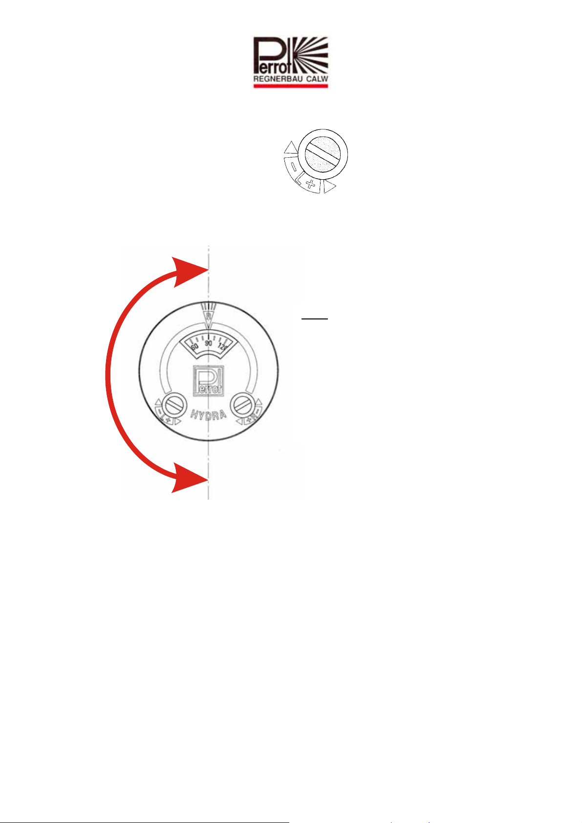
6 Setting irrigation sector
(Part-circle sprinklers only)
Set the left side stop position using:
Left stop position can be adjusted by +/- 90°
-
Note:
One complete revolution of the
adjuster screw adjusts the sector
stop position by 60°
+
TDP051d+e bunt.doc Rev. 14.06.2010 Seite / Page 26 / 40
Perrot REGNERBAU CALW GmbH Industriestraße 19-27 / D-75382 Althengstett / Germany
Telefon : 0049-7051-162-0 / Fax : 0049-7051-162–133
Page 27
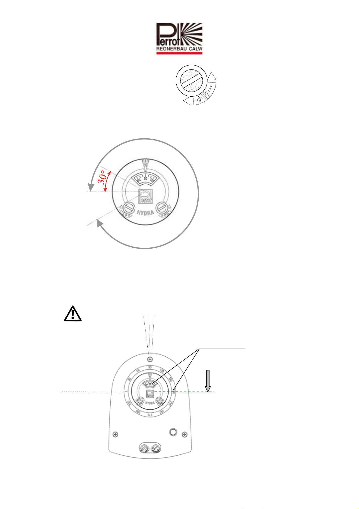
Set right side stop position using:
Right stop position can
be set to a watering sector of 30° to 330°.
330°
Note:
One complete revolution of
the adjustor screw adjusts
the sector stop position by
60°
Note: The number on the rotary scale indicates where, as per the stop
position scale on the right, the sprinkler changes direction.
Note: In order to speed up the setting of the irrigation sector, the sprinkler head can
be manually turned forward with the rotating direction. .
DO NOT TURN BACK!
Left stop position
Right stop
position
Ö
The right stop position
is at the point where these
two values are the same
TDP051d+e bunt.doc Rev. 14.06.2010 Seite / Page 27 / 40
Perrot REGNERBAU CALW GmbH Industriestraße 19-27 / D-75382 Althengstett / Germany
Telefon : 0049-7051-162-0 / Fax : 0049-7051-162–133
Page 28
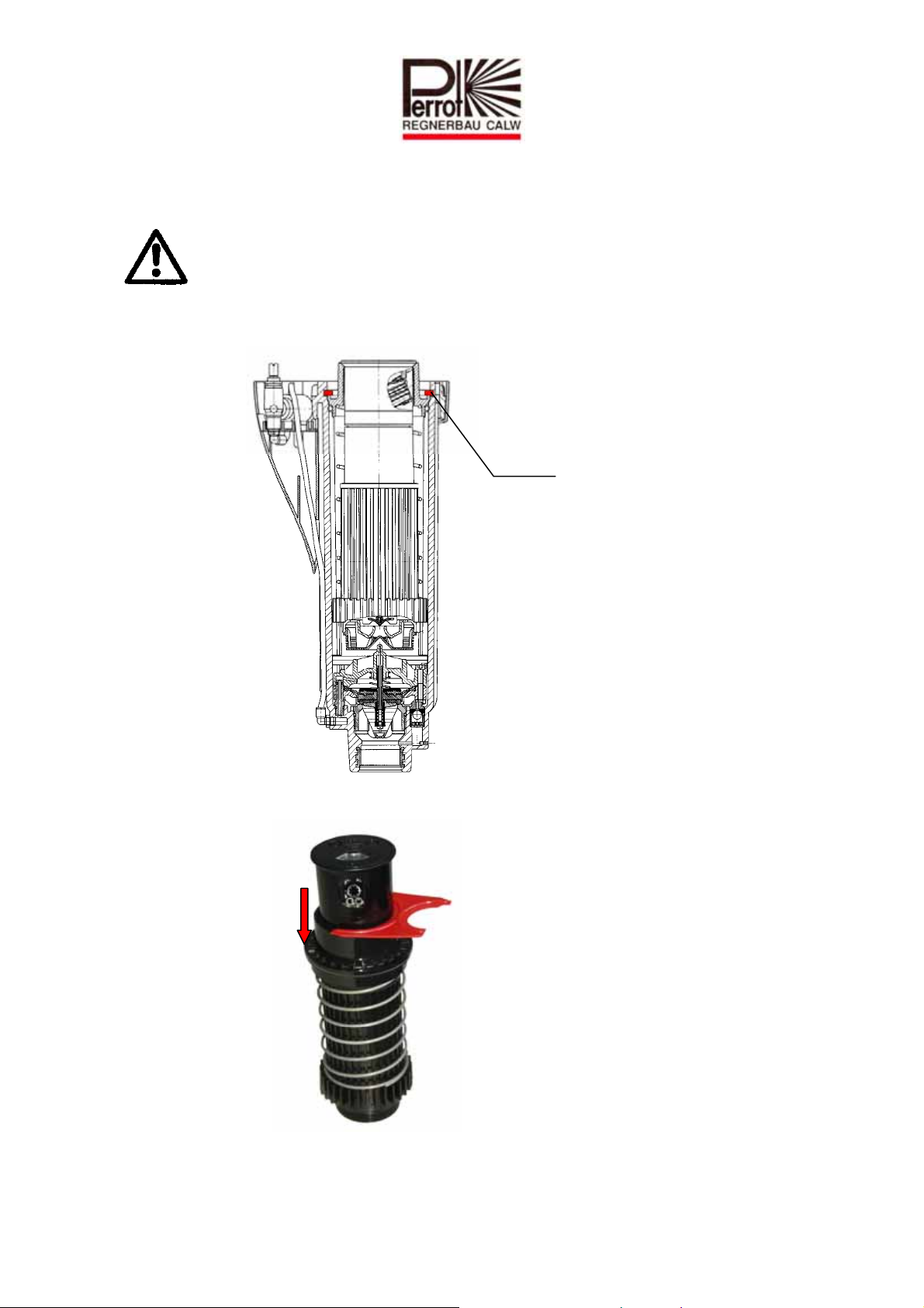
7 Replacing the nozzle
Ensure sprinkler is not under pressure.
Loosen all 3 of the cover’s securing screws and remove cover.
Using a screwdriver, remove white retaining ring.
Retaining ring
Pull sprinkler insert out of the housing
Push down the flange and secure the head with the retainer
Take off sprinkler head cover by levering the cover up at the notch using a small
screwdriver.
Rotate nozzle to the left using pliers and then pull out.
TDP051d+e bunt.doc Rev. 14.06.2010 Seite / Page 28 / 40
Perrot REGNERBAU CALW GmbH Industriestraße 19-27 / D-75382 Althengstett / Germany
Telefon : 0049-7051-162-0 / Fax : 0049-7051-162–133
Page 29
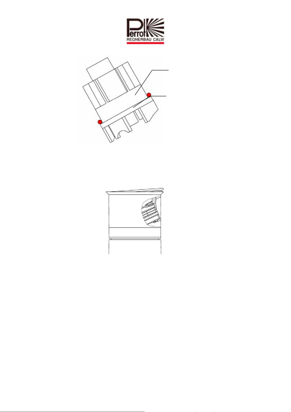
Put O-ring over the new nozzle
O-Ring
and, reversing the procedure, re-install in the sprinkler head.
Fit cover into sprinkler head’s snap-in connection by first pushing it as far as it will
go against the side opposite the nozzle and then snapping it completely into place on
the nozzle side.
TDP051d+e bunt.doc Rev. 14.06.2010 Seite / Page 29 / 40
Perrot REGNERBAU CALW GmbH Industriestraße 19-27 / D-75382 Althengstett / Germany
Telefon : 0049-7051-162-0 / Fax : 0049-7051-162–133
Page 30
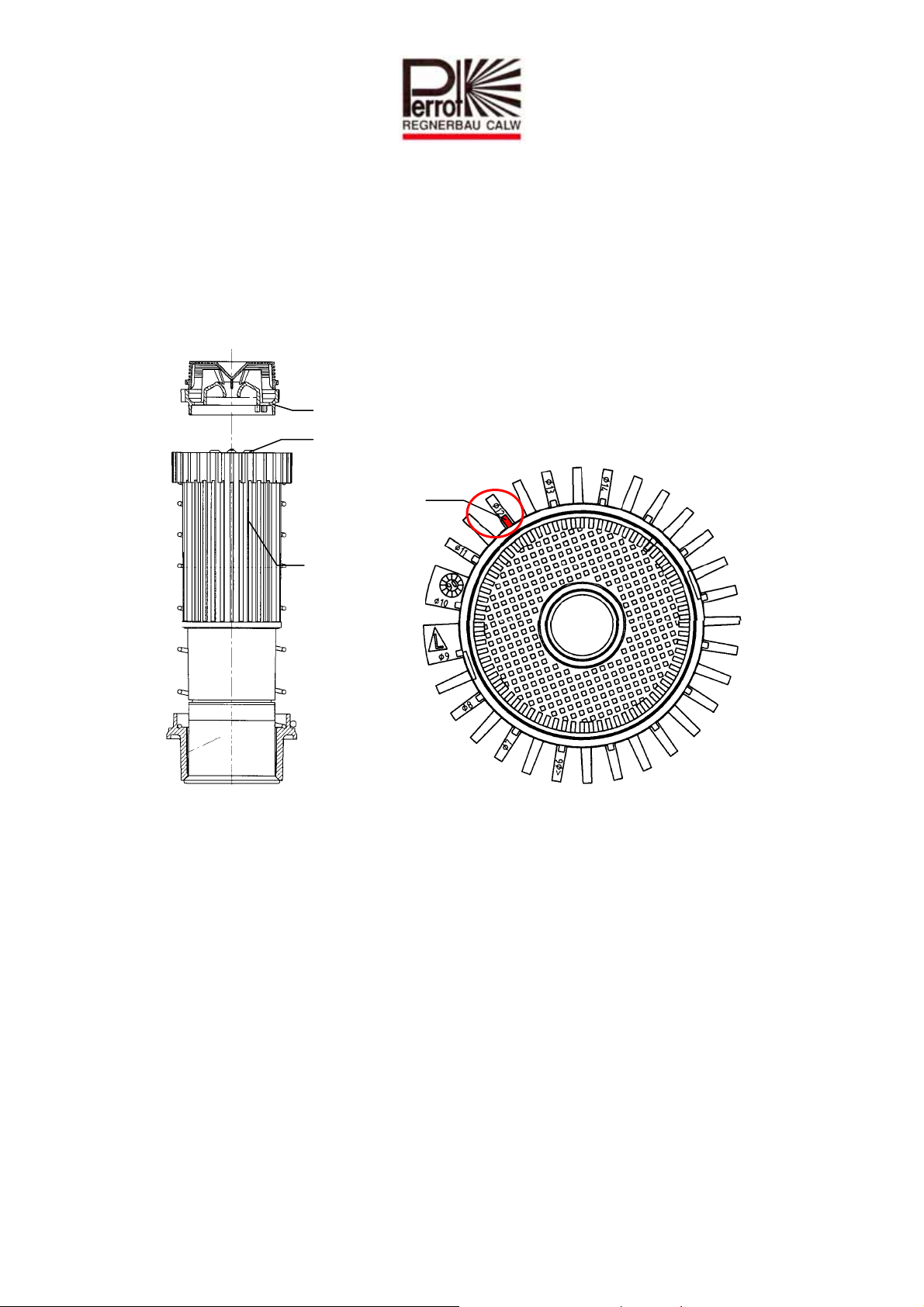
I
d
7.1 Adjusting the inlet nozzle
The recommended rotational speed is maintained by correctly adjusting the inlet nozzle.
Adjust as follows:
Take off inlet nozzle and filter together by using a screwdriver to lever up the inlet
nozzle at the notch.
Snap inlet nozzle back onto the sprinkler module so that the elongated rib is pointing
to the nozzle diameter being used.
nlet nozzle
Turbine
Elongate
rib
Sprinkler
insert
View from above
Note: If you want a higher rotational speed, the rib must be pointing to a smaller
diameter than that of the nozzle actually being used.
TDP051d+e bunt.doc Rev. 14.06.2010 Seite / Page 30 / 40
Perrot REGNERBAU CALW GmbH Industriestraße 19-27 / D-75382 Althengstett / Germany
Telefon : 0049-7051-162-0 / Fax : 0049-7051-162–133
Page 31
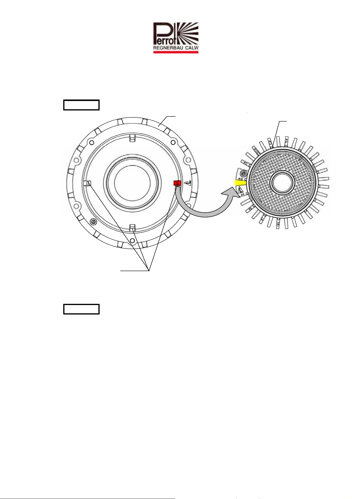
7.2 Fitting the sprinkler insert
Fit O-ring onto flange and lightly grease for easier assembly.
Fit sprinkler module inside housing.
WARNING: Ensure correct alignment.
Guide housing
Guide ribs
Push flange down as far as it will go.
Fit retaining ring.
WARNING: Retaining ring must be fully inserted into the slot.
Secure housing cover using all three screws.
Check sprinkler is working properly as per points 5b-5e.
Sprinkler insert
TDP051d+e bunt.doc Rev. 14.06.2010 Seite / Page 31 / 40
Perrot REGNERBAU CALW GmbH Industriestraße 19-27 / D-75382 Althengstett / Germany
Telefon : 0049-7051-162-0 / Fax : 0049-7051-162–133
Page 32

8 Valve insert removal / installation
H
Ensure sprinkler is not under pressure.
Loosen all 3 cover securing screws and remove cover
Using a screwdriver, remove white retaining ring
Retaining ring
Upper
retaining ring
ollow screw
Lower
retaining ring
Pull sprinkler insert out of the housing
8.1 Taking out the valve
Take off upper and lower retaining ring by hand.
Screw valve lifter / coarse filter wrench onto valve insert’s studs and manually tighten.
Pull out valve insert complete with valve lifter and unscrew. Valve insert is now held
on hollow screw by O-ring only.
TDP051d+e bunt.doc Rev. 14.06.2010 Seite / Page 32 / 40
Perrot REGNERBAU CALW GmbH Industriestraße 19-27 / D-75382 Althengstett / Germany
Telefon : 0049-7051-162-0 / Fax : 0049-7051-162–133
Page 33
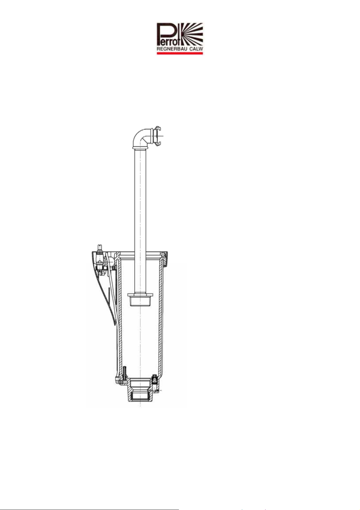
8.2 Taking out the coarse filter – only if seen to be dirty
Insert valve lifter / coarse filter wrench into the filter’s slots, turn and pull out.
Screw in flush insert and flush sprinkler through thoroughly.
TDP051d+e bunt.doc Rev. 14.06.2010 Seite / Page 33 / 40
Perrot REGNERBAU CALW GmbH Industriestraße 19-27 / D-75382 Althengstett / Germany
Telefon : 0049-7051-162-0 / Fax : 0049-7051-162–133
Page 34
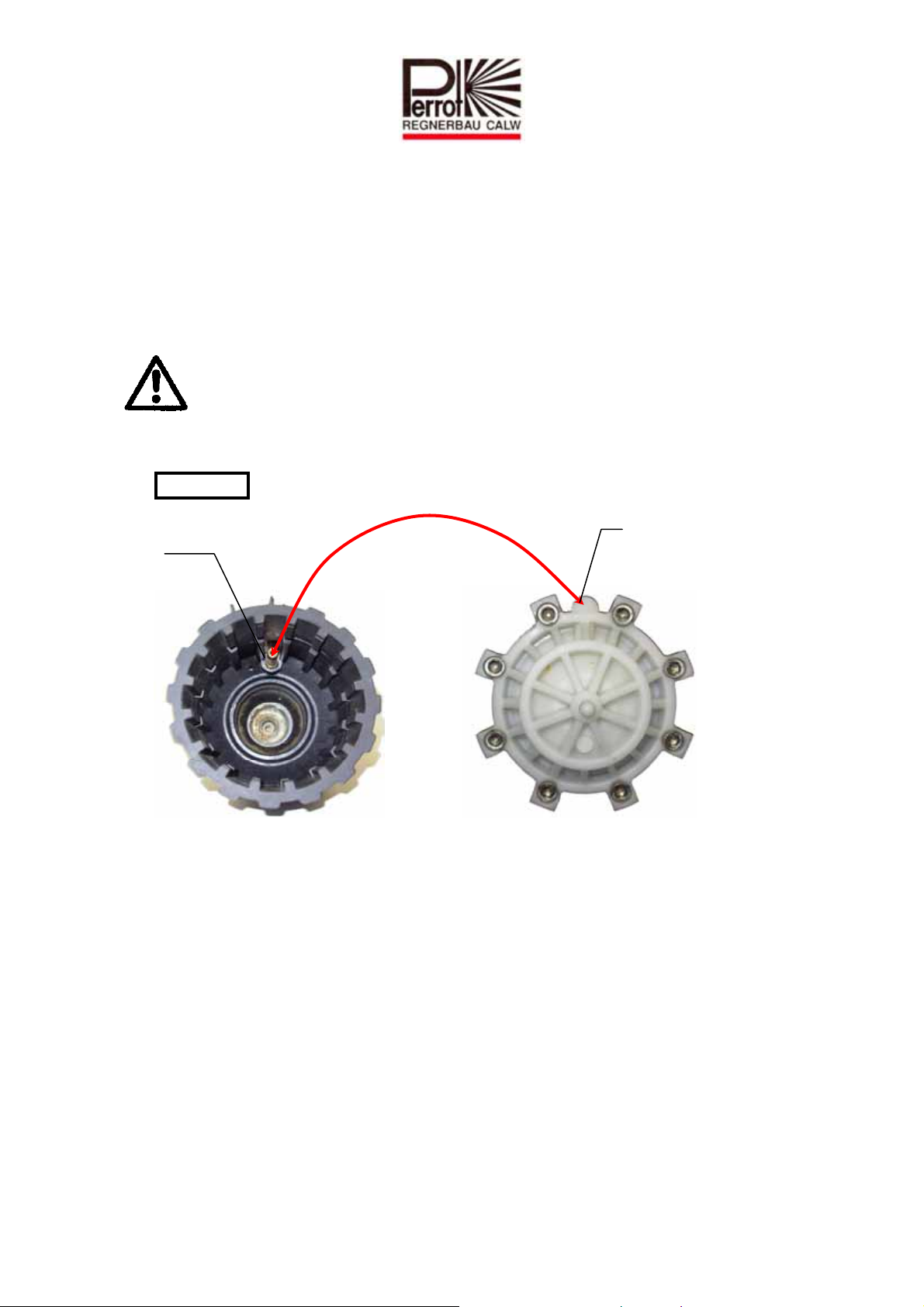
8.3 Fitting coarse filter
E
Twist out flush insert.
Ensure that thread and O-ring are clean.
Lightly smear O-ring with acid-free grease.
Put coarse filter in place and manually tighten using coarse filter wrench.
8.4 Fitting the valve
Before fitting the valve, check the valve insert – especially around the valve seat
– for any dirt or damage!
Screw cleaned or new valve insert onto the valve lifter again and fit into the sprinkler
housing.
WARNING: Ensure it is fitted in the correct position!
Hollow screw
ntry for
hollow screw
TDP051d+e bunt.doc Rev. 14.06.2010 Seite / Page 34 / 40
Perrot REGNERBAU CALW GmbH Industriestraße 19-27 / D-75382 Althengstett / Germany
Telefon : 0049-7051-162-0 / Fax : 0049-7051-162–133
Page 35
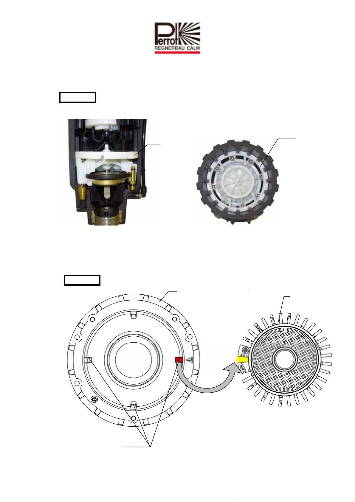
Insert lower retaining ring with bumps facing up and fit lower retaining ring, rotated
by 180°, with bumps facing down.
WARNING: Retaining rings must be fully inserted into the slots!
Retaining
ring
8.5 Fitting the sprinkler insert
Fit O-ring onto flange and lightly grease for easier assembly.
Install sprinkler insert inside housing.
WARNING: Ensure it is fitted correctly aligned!
Retaining
ring
Guide housing
TDP051d+e bunt.doc Rev. 14.06.2010 Seite / Page 35 / 40
Perrot REGNERBAU CALW GmbH Industriestraße 19-27 / D-75382 Althengstett / Germany
Telefon : 0049-7051-162-0 / Fax : 0049-7051-162–133
Guide rib
Sprinkler
insert
Page 36
Push flange down as far as it will go.
Fit retaining ring.
WARNING: Retaining ring must be fully inserted into the slot.
Secure housing cover using all three screws.
Check sprinkler is working properly as per points 5b - 5e.
9 Control unit removal / installation
Ensure sprinkler is not under pressure.
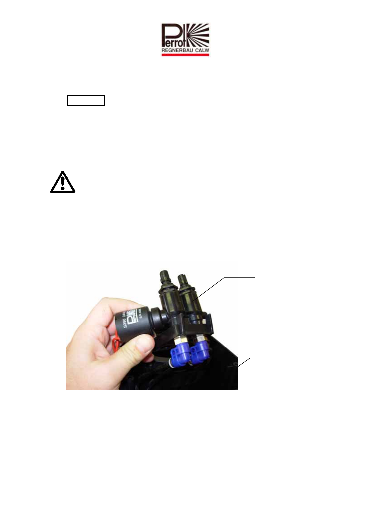
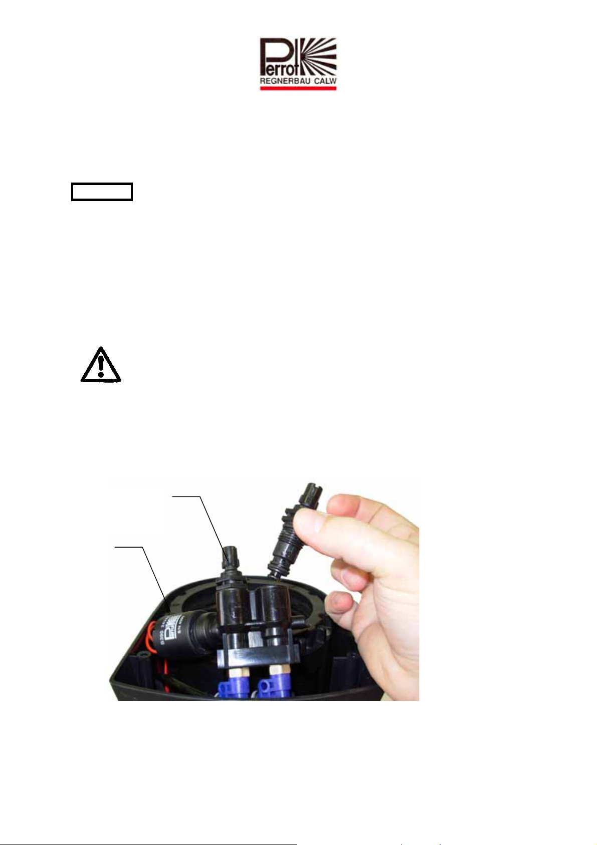
9.1 Taking out the control unit
Loosen all 3 cover-securing screws and remove cover.
Unclip control unit from protective casing and lift up.
Twist out coil.
When replacing the control unit, cut off the hoses as close as possible to the unit’s
nozzle.
Control unit
Sprinkler
TDP051d+e bunt.doc Rev. 14.06.2010 Seite / Page 36 / 40
Perrot REGNERBAU CALW GmbH Industriestraße 19-27 / D-75382 Althengstett / Germany
Telefon : 0049-7051-162-0 / Fax : 0049-7051-162–133
Page 37
l
9.2 Fitting the control unit
When buying a replacement, the control unit is supplied with plug-and-socket
connections. Push hoses into plug-in nozzles as far as they will go and ensure that the
mounting ring springs back
WARNING: Please ensure that the hoses are fitted in the correct position. Otherwise the
sprinkler will not work.
Screw in coil.
Clip control unit into protective casing.
Secure housing cover using all three screws.
Check sprinkler is working properly as per points 5b - 5e.
10 Removal / fitting of manual opening and pressure regulating inserts
Ensure sprinkler is not under pressure.
10.1 Removal of manual opening and pressure regulating inserts
Loosen all 3 cover-securing screws and remove cover.
Unclip control unit from protective casing and lift up.
Using an SW19 flat spanner, twist out manual opening and pressure regulator screws.
Control unit
Coi
TDP051d+e bunt.doc Rev. 14.06.2010 Seite / Page 37 / 40
Perrot REGNERBAU CALW GmbH Industriestraße 19-27 / D-75382 Althengstett / Germany
Telefon : 0049-7051-162-0 / Fax : 0049-7051-162–133
Page 38

10.2 Fitting manual opening and pressure regulating inserts
Set manual opening to Auto and pressure regulator into the minus (-) position (turn to
the left as far as it will go) and screw in using an SW19 flat spanner.
Clip control unit into protective casing.
Secure housing cover using all three screws.
Check sprinkler is working properly as per points 5b - 5e.
Set manual opening / pressure regulator screws to desired position.
11 Maintenance
Cut sprinkler housing free of any overgrowing grass. It makes sense to do this work
with the cut off tool (see chapter 4 for the order number) before starting up the system
in spring.
TDP051d+e bunt.doc Rev. 14.06.2010 Seite / Page 38 / 40
Perrot REGNERBAU CALW GmbH Industriestraße 19-27 / D-75382 Althengstett / Germany
Telefon : 0049-7051-162-0 / Fax : 0049-7051-162–133
Page 39
12 Troubleshooting
12.1 Malfunctions
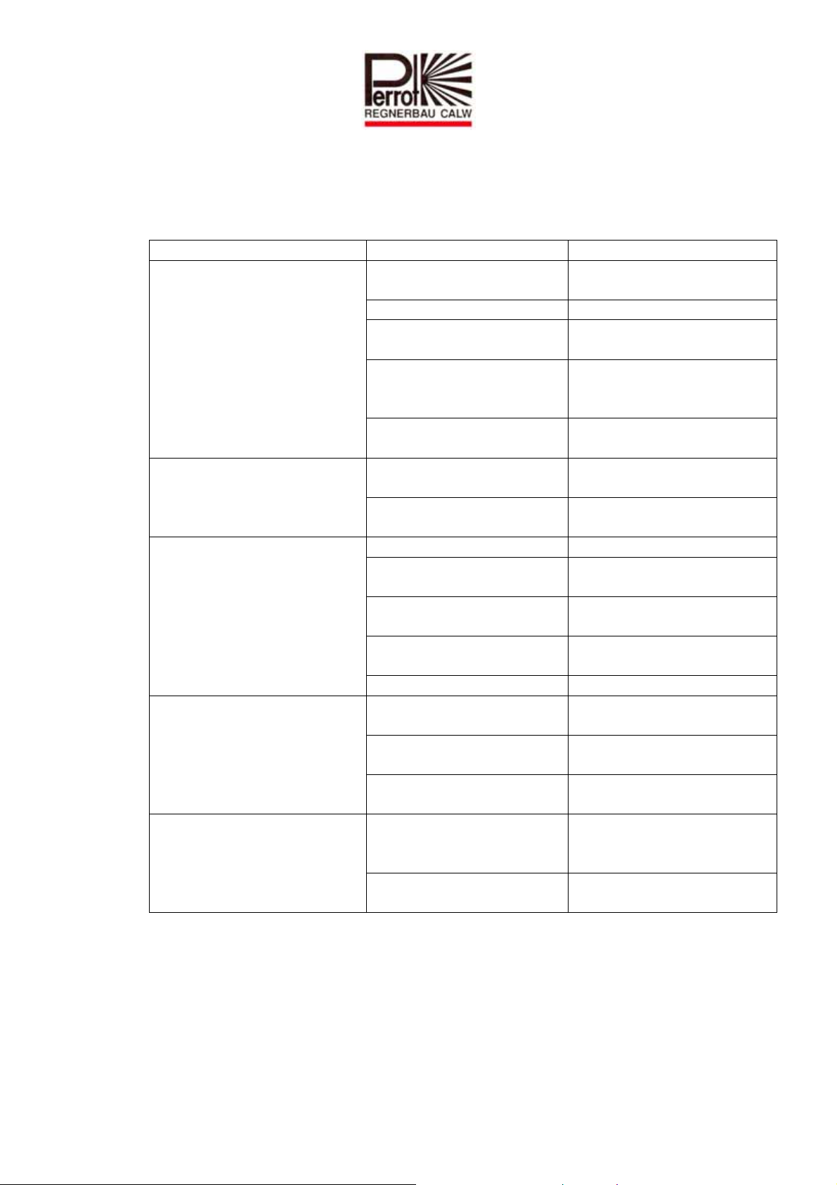
Problem Cause Remedy
Valve opens/closes only with
manual opening, but not on
any electric signal
Valve fails to open even with
manual opening
Valve fails to close
Rotary speed too low / too
high or does not rotate at all
Output pressure at sprinkler
nozzle too low or casting
range too short
Subject to change without prior notice.
Screw for ‘Manual
opening’ is set to OFF
Turn screw to the left as far
as it will go
Core is jammed in the coil Take out coil and clean core
No / inadequate power
supply
Establish 24V AC power
supply
Coil defective Check coil resistance (should
be ca. 35 ohms) and replace
if necessary
Overflow channel from coil
Clean channel
clogged
Control water hole or relief
hole clogged
Feeder pipeline under no /
Clean control water / relief
hole
Establish pressure supply
insufficient pressure
Coil seat dirty Clean coil seat
Bits of dirt between valve
seat and sealing plate
Clean valve seat and sealing
plate
Diaphragm defective Take out valve and replace
diaphragm
Insufficient drop in pressure
at the valve
Tighten ‘pressure regulator
screw’
Control water filter dirty Clean control water filter
Inlet nozzle incorrectly set
(see chapter 7)
Turbine blocked by stones
Set inlet nozzle to correct
nozzle diameter
Clean turbine
or bits of dirt
Inlet nozzle or filter have
Clip parts together again
worked loose
Stones and bits of dirt are
hindering an unimpeded
Clean valve and flush
sprinkler
flow-through of water
Pressure regulator in minus
(-) position
Turn pressure regulator
screw to the left towards (+)
TDP051d+e bunt.doc Rev. 14.06.2010 Seite / Page 39 / 40
Perrot REGNERBAU CALW GmbH Industriestraße 19-27 / D-75382 Althengstett / Germany
Telefon : 0049-7051-162-0 / Fax : 0049-7051-162–133
Page 40

Für weitere Informationen stehen wir Ihnen gerne zur Verfügung.
We remain at your full disposal for any further information you may require!
REGNERBAU CALW GmbH
Industriestrasse 19-29
75382 Althengstett / Germany
Tel. +49 / 7051 / 162-0
Fax. +49 / 7051 / 162-133
http://www.perrot.de
TDP051d+e bunt.doc Rev. 14.06.2010 Seite / Page 40 / 40
Perrot REGNERBAU CALW GmbH Industriestraße 19-27 / D-75382 Althengstett / Germany
Telefon : 0049-7051-162-0 / Fax : 0049-7051-162–133
 Loading...