

Page 1
FEATURES
houseofrohl.com
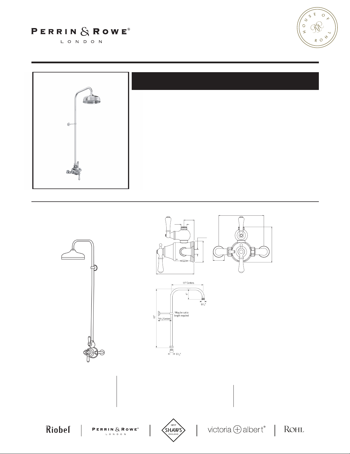
GEORGIAN ERA™ 3/4" EXPOSED WALL MOUNT THERMOSTATIC
SHOWER SYSTEM
U.GA19WSLS (Lever Handles)
U.GA19WSX (Cross Handles)
• Shower package components:
- U.5751LS or U.5752X - Exposed Therm Mixer
- U.5381 - 63” Riser
-
U.5205 - 8” Showerhead
U.GA19WS
For warranty or additional information, contact:
G 3/4”
6 3/4”
3/4” Center
U.5381
3/4” NPT
Ø3 3/4”
U.5751
7 7/8” Center s
5 7/8 ”
Ø2”
U.5205
US customers
U.S.A.
HOUSEOFROHL.COM
1-800-777-9762
Canadian customers
QUEBEC / MARITIMES / WESTERN CANADA
QUÉBEC / MARITIMES / OUEST CANADIEN
QUEBEC / MARITIMOS / CANADA OCCIDENTAL
HOUSEOFROHL.CA
1-866-473-8442
ON TAR I O
HOUSEOFROHL.CA
1- 800 -287-53 54
Page 2
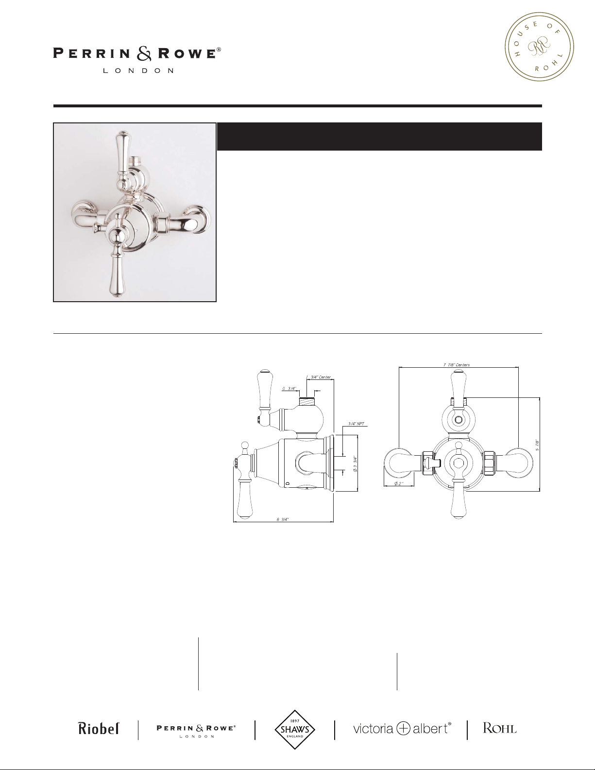
Georgian Era Exposed Therm Valve with Volume and
Temperature Control
U.5751LS
FEATURES
• Inlets 7 7/8" center-to-center
• Inlets 3/4" female NPT
• CNC machined from solid brass bar
stock, not cast
• Exposed thermostatic valve
• Volume control, lever handles
• True 3/4" inlets and waterways
for high output
• U.5398 secondary outlet adapter
required for bottom outlet tub spout
connection
• Additional functions should go off top
with U.5397
• 14-16 GPM
houseofrohl.com
US customers
U.S.A.
HOUSEOFROHL.COM
1-800-777-9762
For warranty or additional information, contact:
Canadian customers
QUEBEC / MARITIMES / WESTERN CANADA
QUÉBEC / MARITIMES / OUEST CANADIEN
QUEBEC / MARITIMOS / CANADA OCCIDENTAL
HOUSEOFROHL.CA
1-866-473-8442
ON TAR I O
HOUSEOFROHL.CA
1- 800 -287-53 54
Page 3
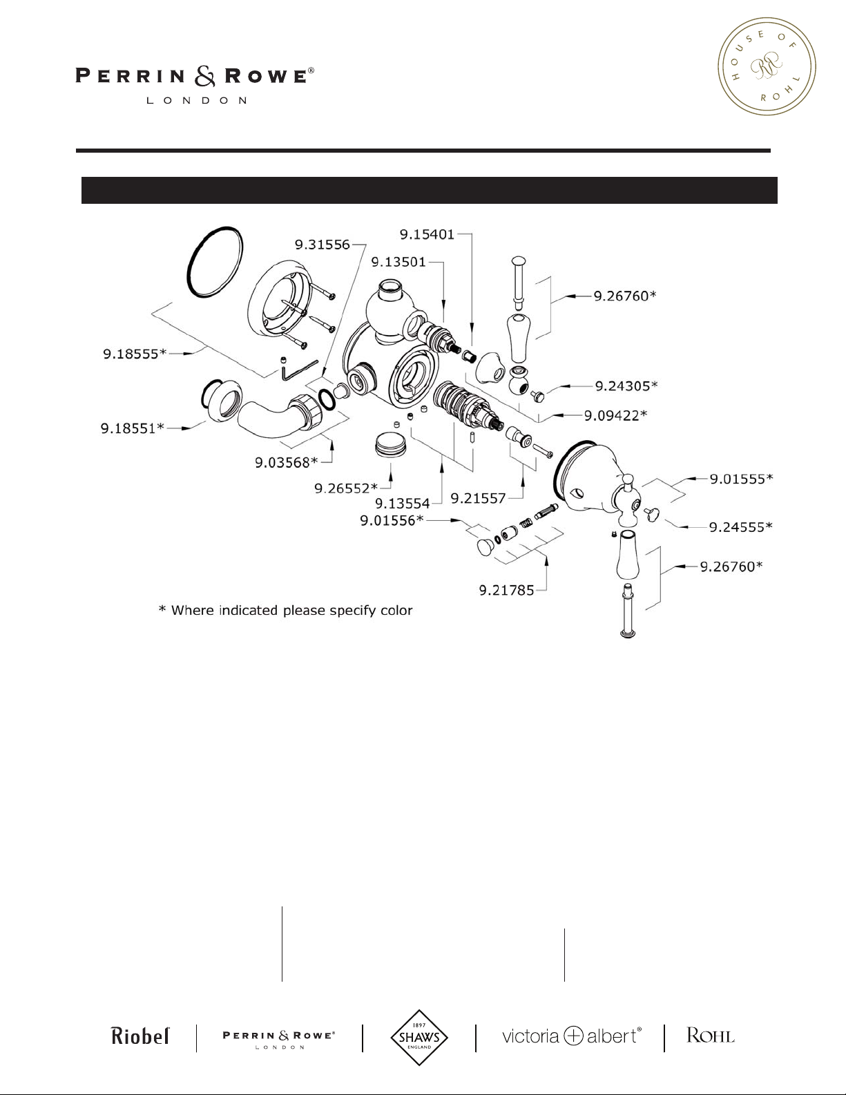
U.5752LS Spare Parts
houseofrohl.com
US customers
U.S.A.
HOUSEOFROHL.COM
1-800-777-9762
For warranty or additional information, contact:
Canadian customers
QUEBEC / MARITIMES / WESTERN CANADA
QUÉBEC / MARITIMES / OUEST CANADIEN
QUEBEC / MARITIMOS / CANADA OCCIDENTAL
HOUSEOFROHL.CA
1-866-473-8442
ON TAR I O
HOUSEOFROHL.CA
1- 800 -287-53 54
Page 4
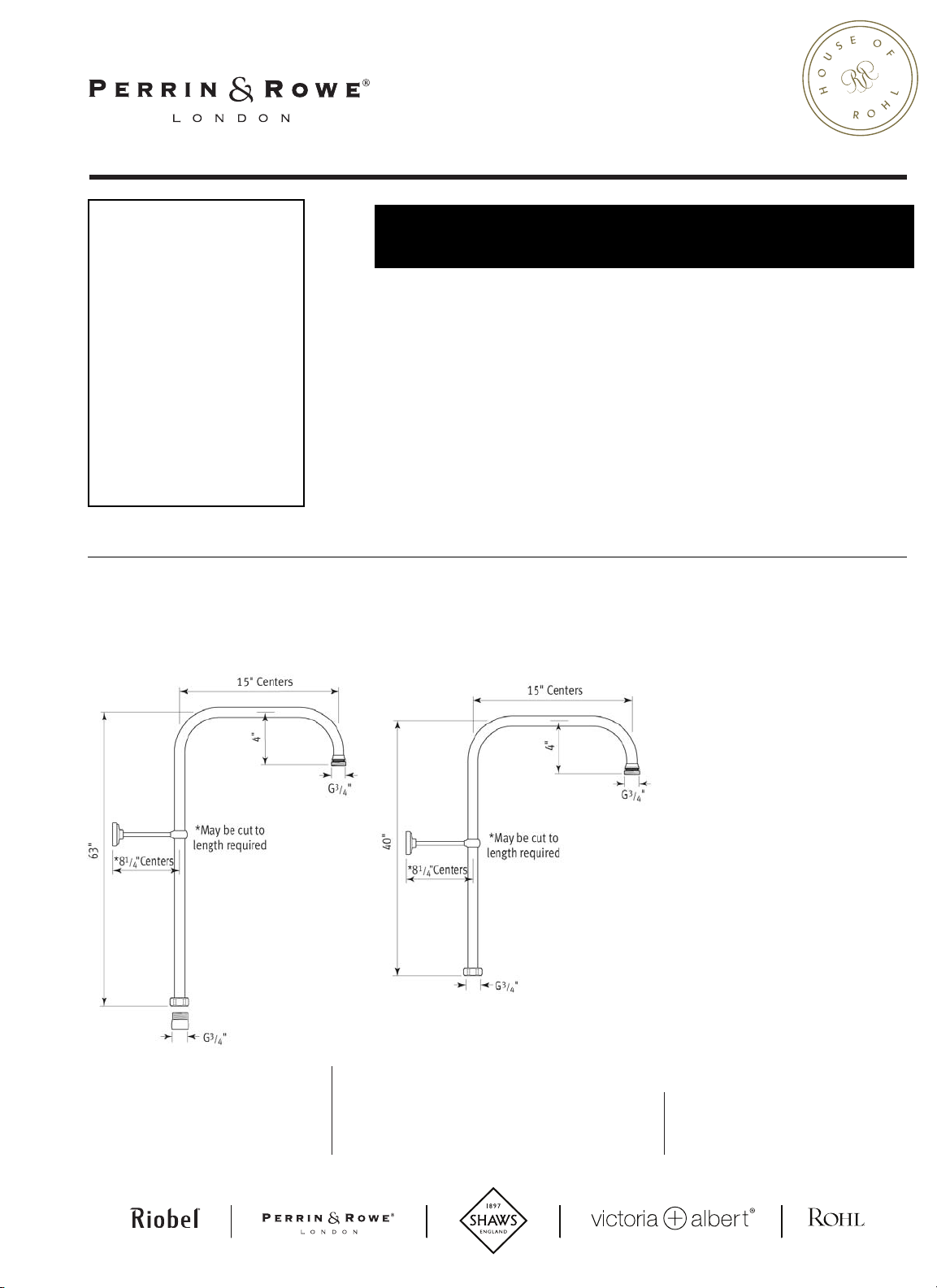
U.5381 (63” riser)
U.5391 (40” riser)
U.5393 (31” riser)
FEATURES
ROHL Perrin & Rowe Bath
U.5391 picured
• F
r use with exposed therm mixers
o
• Direct connection to outlet of shower or
tub/shower mider
• Adjustable 8” stanchion
• Outlet 3/4” NPSM
• May be cut to length required
Rigid Riser Shower Outlets
U.5391
houseofrohl.com
U.5393
5381
US customers
U.S.A.
HOUSEOFROHL.COM
1-800-777-9762
For warranty or additional information, contact:
Canadian customers
QUEBEC / MARITIMES / WESTERN CANADA
QUÉBEC / MARITIMES / OUEST CANADIEN
QUEBEC / MARITIMOS / CANADA OCCIDENTAL
HOUSEOFROHL.CA
1-866-473-8442
ON TAR I O
HOUSEOFROHL.CA
1- 800 -287-53 54
Page 5

Riser Spare Parts
houseofrohl.com
US customers
U.S.A.
HOUSEOFROHL.COM
1-800-777-9762
For warranty or additional information, contact:
Canadian customers
QUEBEC / MARITIMES / WESTERN CANADA
QUÉBEC / MARITIMES / OUEST CANADIEN
QUEBEC / MARITIMOS / CANADA OCCIDENTAL
HOUSEOFROHL.CA
1-866-473-8442
ON TAR I O
HOUSEOFROHL.CA
1- 800 -287-53 54
Page 6
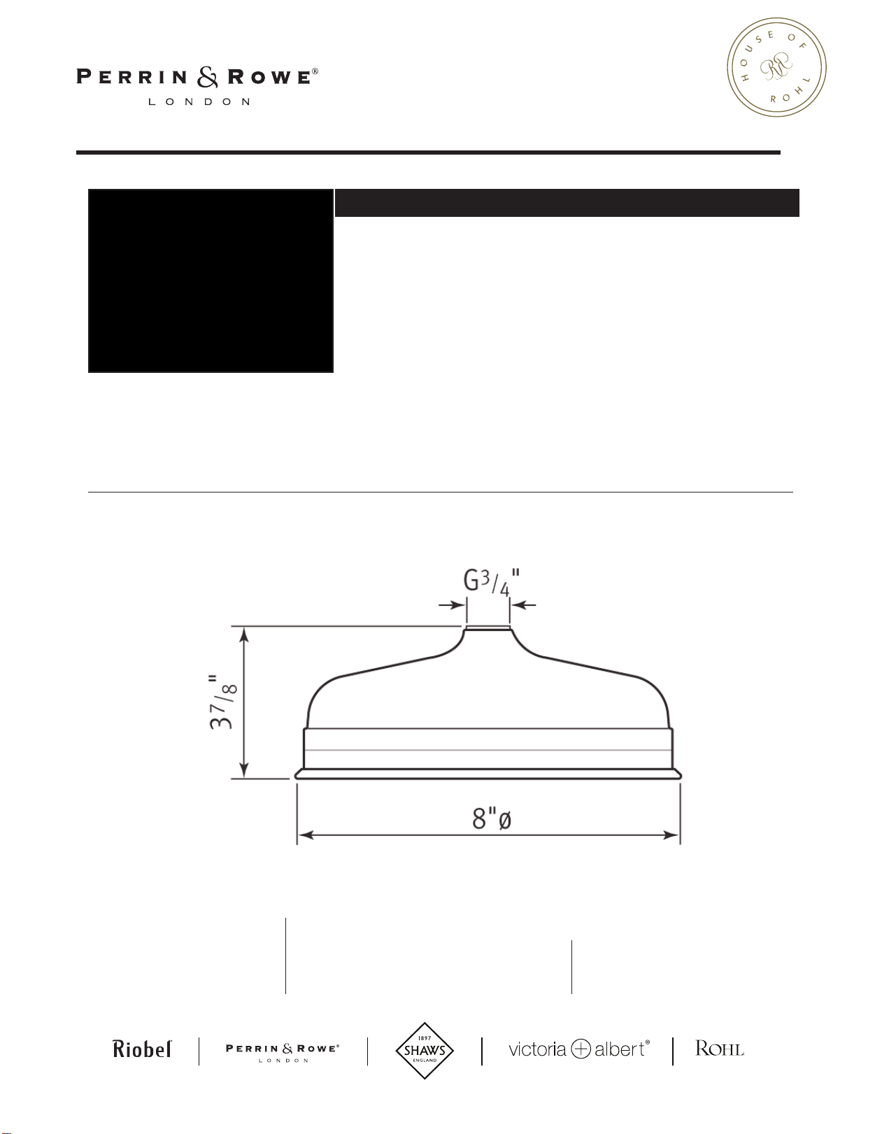
FEATURES
• Large 8” diameter faceplate
• Single function rain spray pattern
• Body constructed of brass
• 3/4” NPSM connection
• Flow rate 2.0 GPM
houseofrohl.com
8” Showerhead
ROHL Perrin & Rowe®Bath
U.5205
US customers
U.S.A.
HOUSEOFROHL.COM
1-800-777-9762
For warranty or additional information, contact:
Canadian customers
QUEBEC / MARITIMES / WESTERN CANADA
QUÉBEC / MARITIMES / OUEST CANADIEN
QUEBEC / MARITIMOS / CANADA OCCIDENTAL
HOUSEOFROHL.CA
1-866-473-8442
ON TAR I O
HOUSEOFROHL.CA
1- 800 -287-53 54
Page 7
E XP OS E D M IX ER - U . 55 5 0 , U .5 5 5 0L S & U . 57 51 L
9.13554
9.26555
9.01556*
9.21556*
9.01561*
9.21557
9.12555*
9.12556*
9.154014
9.13501
9.18555*
9.31556
9.03568*
9.01562*
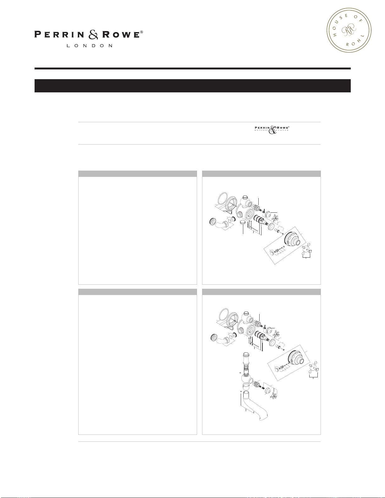
Spare Parts - *Where indicated specify color
E XP OS E D M IX ER - U . 35 5 2 & U . 35 52 LS
9.13554
9.01561*
9.12556*
9.13501
9.18555
9.31556
9.18551*
9.03568*
9.01556*
9.21556*
9.01562*
9.12556*
9.01561
9.13501
9.20556*
9.21557
9.12555*
E x p o s e d T h e r m o s t a t i c S h o w e r M i x e r
S p a r e P a r t s
U . 3 5 5 2 L • U . 3 5 5 6 X • U. 5 5 5 0 L • U . 5 5 5 2 X
8
7
6
5
9
4
1
2
3
1
2
3
4
5
8
9
6
7
8
7
6
5
9
4
1
2
3
1
2
3
4
5
8
9
6
7
houseofrohl.com
INSTALLATION INSTRUCTIONS
E x p o s e d T h e r m o s t a t i c S h o w e r M i x e r
P a r t s C h e c k L i s t
U . 3 5 5 2 L • U . 3 5 5 6 X • U . 5 5 5 0 L • U . 5 5 5 2 X
Congratulations on the purchase of your Perrin & Rowe Thermostatic Shower.
Correctly installed and with sensible care, it will give many years of trouble free service.
Before you start...please read this leaflet.
We recommend employing the services of a registered plumber.
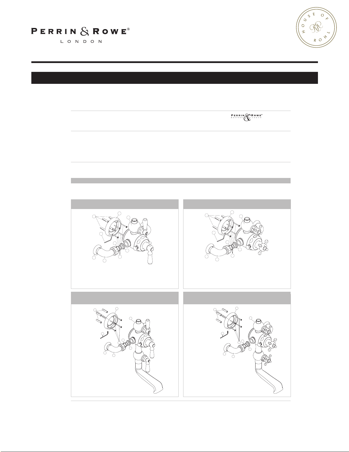
P AR T S C H EC K LI S T
Please check carefully that the contents of your Perrin & Rowe Shower Mixer is complete. Please check before you install the product that there
is no damage to the contents as we cannot accept any responsibility after installation.
E XP OS E D T H E RM O ST AT I C S H OW E R M IX E R U .5 55 0L & U. 5 7 51 L
E XP OS E D T H E RM O ST AT I C S H OW E R M IX E R U .5 55 2X & U. 5 7 52 X
1 Rawl Plugs x 4
2 Back Plate
3 Mixer Body
4 2.5mm AF Hexagonal Key
5 Back Plate Screws x 4
6 Strainers x 2
7 O’Ring Seals x 2
8 Elbow Unions x 2
9 Rosettes x 2
W AL L MO U N TE D EX PO SE D TH E R MO S TA T IC S HO W ER
M IX ER W IT H O UT L E T T O BA TH - U .3 55 2L
1 Rawl Plugs x 4
2 Back Plate
3 Mixer Body
4 2.5mm AF Hexagonal Key
5 Back Plate Screws x 4
6 Strainers x 2
7 O’Ring Seals x 2
8 Elbow Unions x 2
9 Rosettes x 2
1 Rawl Plugs x 4
2 Back Plate
3 Mixer Body
4 2.5mm AF Hexagonal Key
5 Back Plate Screws x 4
6 Strainers x 2
7 O’Ring Seals x 2
8 Elbow Unions x 2
9 Rosettes x 2
W AL L MO U N TE D EX PO SE D TH E R MO S TA T IC S HO W ER
M IX ER W IT H O UT L E T T O BA TH - U .3 55 6
1 Rawl Plugs x 4
2 Back Plate
3 Mixer Body
4 2.5mm AF Hexagonal Key
5 Back Plate Screws x 4
6 Strainers x 2
7 O’Ring Seals x 2
8 Elbow Unions x 2
9 Rosettes x 2
Page 8
INSTALLATION INSTRUCTIONS
2"
Tub Rim
5
/
8
" Max
3
/
4
" NPT
Wall
7
7
/
8
" Centers
E x p o s e d T h e r m o s t a t i c S h o w e r M i x e r
I n s t a l l a t i o n
U . 3 5 5 2 L • U . 3 5 5 6 X • U . 5 5 5 0 L • U . 5 5 5 2 X
houseofrohl.com
C HE CK L IS T
˚
! Temperature of the hot water supply does not exceed 82
C (180˚F)!
! Recommended minimum water supply pressure - 0.2 bar (2.9psi) !
! Recommended maximum water supply pressure - 10 bar (145psi) !
deal performance obtained with equal hot & cold pressures !
! I
P RE PA R AT I O N
Flush the plumbing system before installing the shower. This is to
remove plumbing residues. This is especially important where
extensive plumbing work has been carried out.
The Hot supply should be on the left when viewed from the front
of the fit ting.
We recommend hot and cold supplies should have conveniently
plac
ed isolating valves to accommodate any servicing
requirements.
If the bottom outlet is being utilized for a hand shower, rain bar,
or body sprays and the showerhead on the
top outlet is being used at the same time, it
is possible that there may be a temperature
variation between the outlets. If you need
to run two functions at once, the system
should be designed using only one outlet.
Plea
se ensure that the installation complies
with the local plumbing codes.
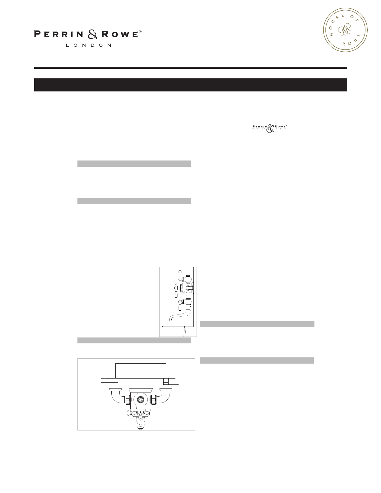
When fitting U3556, U3552 or U3552LS
they should be positioned to allow an air
gap of 2” above the tub rim (see diagram).
Check compliance with local plumbing
codes.
I NS TA L LA TI O N
”
1 Fit two
3
/
NPT male fittings into wall at 7
4
7
” centers.
/
8
2 Fit and seal, the correct length for your installation, a 3/
male nipple (not supplied) into the female fitting so that no more
5
”
than
/
of thread is protruding from the wall surface.
8
3 Apply thread sealing material to shank and with rosette in place,
screw union onto shank. Turn union to required position.
4 Flush the plumbing system to remove plumbing residues prior to
fitting shower.
5 Temporarily fit the shower body between the two unions and
adju
st the position if necessary.
6 With the shower body still in position, mark the position of the
backplate on the wall.
7 Remove the shower body and using the backplate as a template,
with the grubscrew facing down, mark the positions of the fixing
holes.
”
NPT
4
8 Secure backplate to the wall using plugs and screws provided.
9 Place shower body into backplate and t
10 Fully tighten union coupling nut onto shower inlet union by hand
to hold body into position. Ensure that the ‘O’ ring
sufficiently
seals and filter meshes are in position between the surfaces of
the wall union and the shower inlet union.
only. If you need to use a wrench, protect nuts with a cloth or
tape.
ighten grubscrew
11 Fully tighten grubscrew in backplate.
12 Slide rosette up to finished wall surface.
BEF
O RE U SE
Carefully check the installation for leaks.
If further building work is to be carried out in the vicinity, cover
the thermostatic shower mixer with a plastic bag to avoid
damaging the finish.
C AR E & M AI N T EN A N CE
Wipe down after use to avoid water spotting and mineral build up.
Occasional cleaning with warm soapy water, followed by a polish with
a soft cloth is all that is required to keep
condition.
use proprietary abrasive liquids, powders, or pads to clean the
Do not
shower. Do not use any products with ammonia bleach or limescale
remover. You will damage the plated finish and void your guarantee.
the plated finish in good
Page 9
INSTALLATION INSTRUCTIONS
COLD SHOWER ONLY:
Pull out override stop and turn lever/crosshea
d anti-clockwise.
If w
ater temperature increases:
Pre-set temperature too low and needs adjusting. See Section 1.
If water temperature decreases:
Cold supply feeding into hot inlet.
Cold supply should feed into RH side.
If water temperature unchanged:
a) Hot supply temperature too low. Minimum 65˚C. (149˚F).
b) Faulty cartridge. See section 2.
HOT SHOWER ONLY:
Turn lever/crosshead clockwise.
If water temperature decreases:
Pre-set
temperature too high and needs adjusting. See section 1.
If water temperature increases:
Hot supply feeding into cold inlet.
Hot supply should feed into LH side.
If water temperature unchanged:
a) Cold supply temperature too high. Maximum 22˚C. (72˚F).
b) Faulty cartridge. See section 2.
FLOW PROBLEMS:
Flow Gradually decreases:
a) Debris collecting in pipework. See section 3.
b) Debris collecting in filters. See section 3.
Flow s
uddenly stops: (Built in Safety Feature)
a) Supply failure. See section 3.
b) Debris blocking pipework. See section 3.
c) Debris blocking filters. See section 3.
No flow on start up:
a) Extremely low flow. See section 4.
b) Supply failure. See section 3.
c) Non-return valve in inlets not opening. See section 4.
d) Shut off valve not opening. See section 5.
SECTION 1
The thermos
tatic shower cartridge is pre-set to give a shower
temperature of 38˚C. (100˚F). If shower temperatures different to the
pre-set temperature are
required the cartridge can be
adjusted using the following
procedure.
Important: Altering the pre-set
shower temperature will also
alter the maximum and
minimum operating
temperatures.
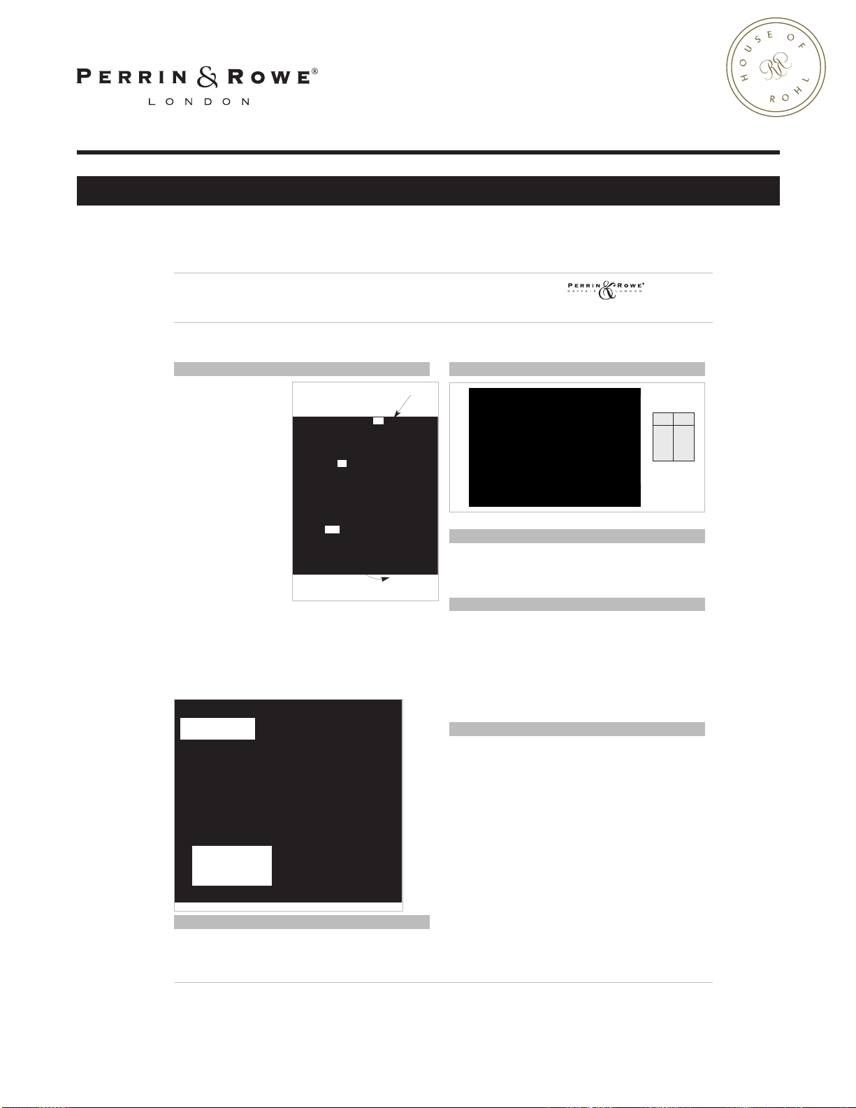
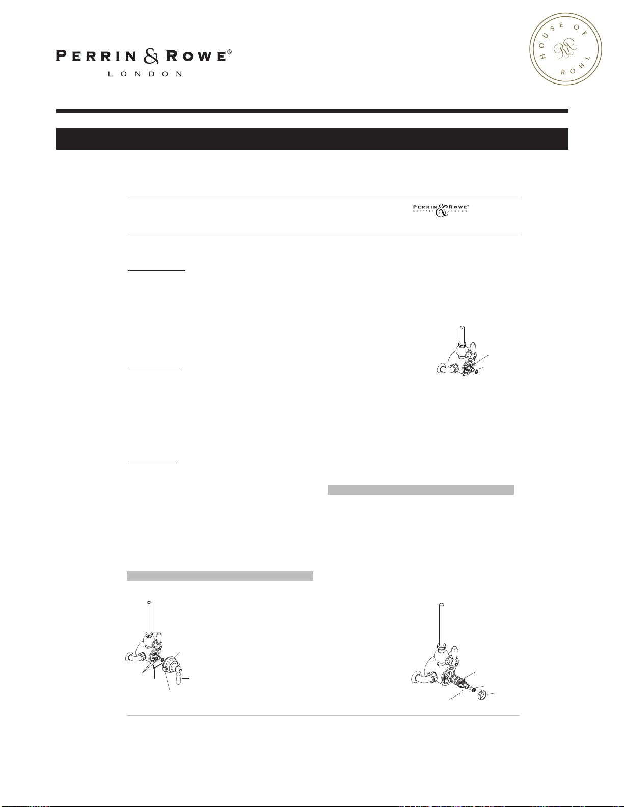
Hood Removal. See figure 1.
Undo the three grub screws on
the underside of the body
usin
g a 3mm AF Allen key. Do
E x p o s e d T h e r m o s t a t i c S h o w e r M i x e r
T r o u b l e s h o o t i n g
U . 3 5 5 2 L • U . 3 5 5 6 X • U . 5 5 5 0 L • U . 5 5 5 2 X
Figure 1
Grub Screws
3mm AF
Allen Key
Override
Stop
Temperature
Control
Lever/Crosshead
Hood
Figure 2
Alignment
Groove
Black Alignment
Dot
Figure 3
Alignment Pin
Large Brass
Locking Nut
Thermostatic Cartridge
Spindle
E x p o s e d T h e r m o s t a t i c S h o w e r M i x e r
O p e r a t i o n & T e c h n i c a l D a t a
U . 3 5 5 2 L • U . 3 5 5 6 X • U . 5 5 5 0 L • U . 5 5 5 2 X
houseofrohl.com
O PE RAT IO N
To operate the shower,
rotate the flow control
lever/crosshead clockwise a
quarter turn. See figure A.
The thermostatic cartridge is
pre-set by the manufacturer
to give a shower
temperature of 38
when the lever is in the
vertical position/or the ‘dot’
on the Crosshead boss is at
the top. To achieve a colder
shower rotate the
lever/crosshead clockwise.
See Figure A. To achieve a
hotter showe
override
lever/crosshead anticlockwise up to a maximum
˚
C (111˚F). See figure
of 44
B. It is recommended that
the temperature control be
returned to its pre set
position when finished.
Anti-Scald
The thermostatic cartridge will automatically shut down completely on
failure of either the hot or cold supply. This is especially important if
your shower is to be used by ch
cartridg
Temperature Override
Mechanism
Factory preset
temperature 100˚F
Maximum temperature
obtainable 111˚F
Figure B.
Temperature override mechanism
˚
C (100˚F)
r, pull out the
knob and rotate the
Figure A.
Operating Lever Controls
e will reactivate when the supply failure has been corrected.
ildren or the elderly. The thermostatic
TEMPERATURE
CONTROL LEVER
ON
COLD
FLOW CONTROL
LEVER
OFF
PRESET
C AR TR I D GE T EM P E RA T UR E
If shower temperatures different to the pre-set are required, the
cartridge can be adjusted using the procedure in Section 1 of the
Troubleshooting Guide on the following pages.
CARTRIDGE PER FORMANCE DATA FOR THERMOSTATIC UNIT ONLY
psi gpm
45 9.2
60 11
Flow Rate (gpm)
Pressure
T EC H N IC A L D AT A
Working pressures: 1 bar min (15psi), 10 bar max (145psi).
Shut off supply failure: <1 second.
P ER FO RM AN C E
Factory temperature setting: 38˚C (100˚F)
Temperature range: 11˚C - 44˚C (52-111˚F)
Temperature hot supply: 65˚C - 82˚C (149-180˚F)
Temperature cold supply: 10˚C - 22˚C (50-72˚F)
Temperature Stability: ±1˚C
G UA R A NT E E A ND L IA BI LI TY
Your bathroom product has been manufactured to the high standard
you would expect of any Perrin & Rowe product. But in the unlikely
event that you should experience any defect in the materials or
workmanship within a limited lifetime of purchase, we will replace the
faulty part free of charge. This is provided the product has only been
used for normal domestic purposes and that the installation an
maintenanc
The surface finish is guaranteed for a limited lifetime from the date of
purchase provided our advice concerning care has been observed and
no scouring agents have been used.
Scuffs and scratches caused by normal wear and tear, improper
installation or accidental damage are excluded from the guarantee.
This does not affect your statutory rights. For full ter
ple
e instructions have been observed.
ase contact Rohl.
75 12.9
ms & condition
d
Page 10
INSTALLATION INSTRUCTIONS
Figure 1
Grub Screws
3mm AF
Allen Key
Override
Stop
Temperature
Control
Lever/Crosshead
Hood
Figure 2
Alignment
Groove
Black Alignment
Dot
Figure 3
Alignment Pin
Large Brass
Locking Nut
Thermostatic Cartridge
Spindle
E x p o s e d T h e r m o s t a t i c S h o w e r M i x e r
T r o u b l e s h o o t i n g
U . 3 5 5 2 L • U . 3 5 5 6 X • U . 5 5 5 0 L • U . 5 5 5 2 X
houseofrohl.com
COLD SHOWER ONLY:
Pull out override stop and turn lever/crosshead anti-clockwise.
If water temperature increases:
Pre-set temperature too low and needs adjusting. See Section 1.
If water temperature decreases:
Cold supply feeding into hot inlet.
Cold supply should feed into RH side.
If water temperature unchanged:
a) Hot supply temperature too low. Minimum 65˚C. (149˚F).
b) Faulty cartridge. See section 2.
HOT SHOWER ONLY
:
Turn lever/crosshead clockwise.
If water temperature decreases:
Pre-set temperature too high and needs adjusting. See section 1.
If water temperature increases:
Hot supply feeding into cold inlet.
Hot supply should feed into LH side.
If water temperature unchanged:
a) Cold supply temperature too high. Maximum 22˚C. (72˚F).
b) Faulty cartridge. See section 2.
FLOW PROBLEMS:
Flow Gradually decreases:
a) Debris collecting in pipework. See section 3.
b) Debris collecting in filters. See section 3.
Flow suddenly stops: (Built in Safety Feature)
a) Supply failure. See section 3.
b) Debris blocking pipework. See section 3.
c) Debris blocking filters. See section 3.
No flow on start up:
a) Extremely low flow. See section 4.
b) Supply failure. See section 3.
c) Non-return valve in inlets not opening. See section 4.
off valve not opening. See section 5.
d) Shut
SECTION 1
The thermostatic shower cartridge is pre-set to give a shower
temperature of 38˚C. (100˚F). If shower temperatures different to the
pre-set temperature are
required the cartridge can be
adjusted using the following
procedure.
Important: Altering the pre-set
shower temperature will also
alter the maximum and
minimum operating
es.
temperatur
Hood Removal. See figure 1.
Undo the three grub screws on
the underside of the body
using a 3mm AF Allen key. Do
not completely remove the screws. Detach the hood from the body by
gently pulling on the temperature control lever using an up and down
rocking motion until the hood is free. Place to one side to prevent
damage.
Temperature adjustment. See figure 2.
Temperature adjustments should be carried out while the shower is
running.
The pre-set temperature setting
position is indicated by a black
dot or hole on the brass
spindle, which should
cartridge
be in line with the groove in the
top of the plastic cartridge body.
If it is not in the pre-set
position rotate the cartridge
spindle by hand until it is. Should the required Shower temperature be
different to this setting it can be adjusted by, slowly rotating by hand
clockwise to give a colder shower, slowly rotating by hand
anticlockwise to give a hotter shower. The cartridge has a limited
of less than half a turn in either direction, do not rotate the
rotation
spindle more than this as it would cause permanent damage to the
cartridge. Do not use a screwdriver in the screw on the end of the
cartridge spindle to rotate the spindle.
Re-assembly - The re-assembly of the hood is the reverse of the
removal. Ensure that the temperature control lever/crosshead is in the
al position and rotated against the override stop and remains in
vertic
this position during re-assembly.
SECTION 2
Cartridge Replacement. See figure 3.
Should it be apparent that the cartridge is at fault (ie) unable to adjust
the temperature, it can be replaced by using the following procedure.
Before attempting to remove the cartridge ensure that both hot &
Cold supplies are isolated and the flow control valve is in the off
position.
emove the hood by following the procedure in section 1. Remove the
R
spindle from the cartridge. Undo and remove the large brass locking
nut from around the plastic cartridge body. Remove the alignment pin
situated in a groove between the underside of the cartridge and the
shower body. Pull the cartridge from the shower body, using a pair of
grips or adjustable spanner on the two flat sides of the plastic
cartridg
e body, with a side to
side turning motion to
release the three O’ring
seals. A small amount of
water that is retained in the
shower body will fall out as
the seals are released.
Before replacing the cartridge
ensure that the bore of the
shower body is free from any
dirt and debris.
continued over ...
Page 11
INSTALLATION INSTRUCTIONS
Figure 4
Riser Joint Nut
2.5mm
AF Allen Key
Grub Scew
O'Ring Seal
Supply Filters
Union Nut
Wall Rosette
Figure 5
Inlet Union
Non Return Valve
Figure 6
1/4 turn ceramic valve
Plastic Vernier Insert
Lever/Crosshead
Assembly
Lever Screw
Hood
C HE CK L I S T
! Temperature of the hot water supply does not exceed 82
˚
C (180
! Recommended minimum water supply pressure - 0.2 bar (2.9psi) !
! Recommended maximum water supply pressure - 10 bar (145psi) !
! I
deal performance obtained with equal hot & cold pressures !
P RE PA R AT I O N
Flush the plumbing system before installing the shower. This is to
remove plumbing residues. This is especially important where
extensive plumbing work has been carried out.
The Hot supply should be on the left when viewed from the front
of the fit ting.
We recommend hot and cold supplies should have conveniently
plac
ed isolating valves to accommodate any servicing
requirements.
If the bottom outlet is being utilized for a hand shower, rain bar,
or body sprays and the showerhead on the
top outlet is being used at the same time, it
is possible that there may be a temperature
variation between the outlets. If you need
to run two functions at once, the system
should be designed using only one outlet.
Plea
se ensure that the installation complies
with the local plumbing codes.
When fitting U3556, U3552 or U3552LS
they should be positioned to allow an air
gap of 2” above the tub rim (see diagram).
Check compliance with local plumbing
codes.
I NS TA L LA TI O N
1 Fit two
3
/
4
”
NPT male fittings into wall at 7
7
/
8
” centers.
E x p o s e d T h e r m o s t a t i c S h o w e r M i x e r
I n s t a l l a t i o n
U . 3 5 5 2 L • U . 3 5 5 6 X • U . 5 5 5 0 L • U . 5 5 5 2 X
2"
Tub Rim
5
/
8
" Max
3
/
4
" NPT
Wall
7
7
/
8
" Centers
E x p o s e d T h e r m o s t a t i c S h o w e r M i x e r
T r o u b l e s h o o t i n g
U . 3 5 5 2 L • U . 3 5 5 6 X • U . 5 5 5 0 L • U . 5 5 5 2 X
houseofrohl.com
Section 2 continued ../
Wet the O’rings and push the cartridge into the shower body by hand
alignment pin groove to the bottom. There will be a slight
with the
resistance until the cartridge “snaps” into position. Ensure that the
cartridge is aligned by installing the alignment pin in the groove. Lock
into position using the large brass locking nut. Place the spindle onto
the new valve, aligning the hole with the dot/black line, and with the
groove on the plastic cartridge body.
If at any time during the replacement of the cartridge the spindle
s, return it to the pre-set position. On testing should the required
move
shower temperature be different to this setting it can be adjusted by
following the temperature adjustment procedure in section 1.
SECTION 3
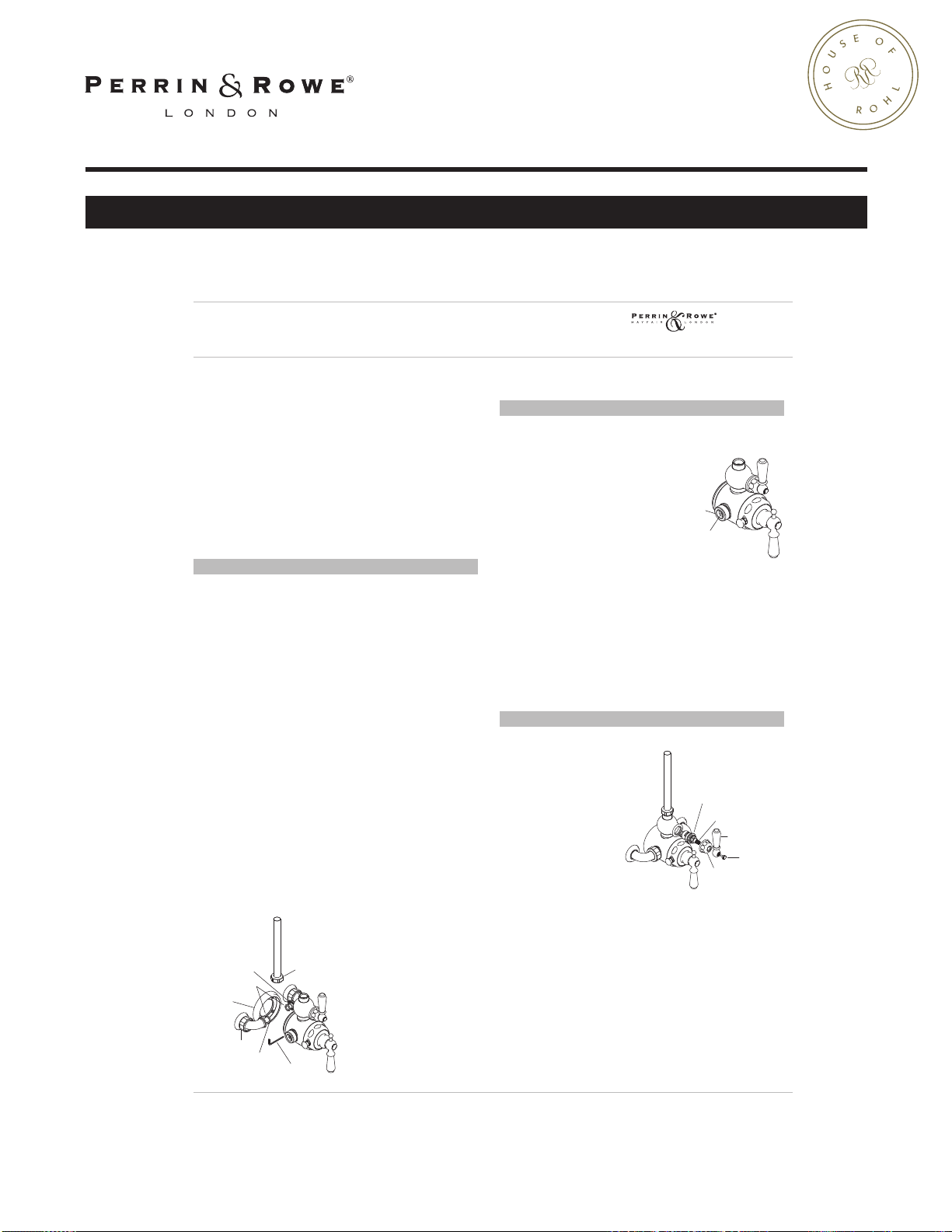
Supply fault / failure. See figure 4.
In order to determine and eliminate a supply fault or failure it will be
necessary to remove the shower body from the installation. BEFORE
TEMPTING TO REMOVE THE SHOWER BODY ENSURE THAT BOTH HOT
AT
AND COLD SUPPLIES ARE ISOLATED.
Take extreme care when working not to damage any of the finished
parts by protecting surfaces of tools with masking/insulating tape.
Undo the supply union nuts and slide them away as far as possible.
Undo the riser joint, slide the nut away from the joint and temporarily
secure out of the way with masking/insulating tape. As soon as the
is broken on the riser joint water will flow from the joint and the
seal
shower outlet connected to the riser. Undo, but do not remove, the
grub screw in the backplate using a 2.5mm AF Allen Key.
Pull the shower body slowly forward, to release body from backplate,
and slowly downwards, to release riser joint. Remove body completely
from installation. Place to one side to prevent damage. The seal
the supply union and the shower body is made with an ‘O’
between
ring. They should remain in the groove in the supply unions. If they fall
out ensure that they are kept to one side to be re used. The filters in
the supply unions can now be removed and inspected for signs of
debris and cleaned. Before replacing the filters flush out the pipework
to ensure that any further debris is removed from the system and that
there i
s an adequate supply.
The supplies can easily be flushed out at this stage by simply turning
them on.
Re-assembly - This is the
reverse of the removal
procedure. Ensure that on both
installations that the ‘O’ ring
seals and filters remain in
position in the supply unions
and that the ‘O’ ring seals are
clean and undamaged. As a
precaution before re-assembly
sure non-return valves
make
are operating freely by pushing
on the centre with a finger. A
small amount of water will fall
out when the non-return valve
opens.
SECTION 4
Non Return Valves. See figure 5.
To examine the non return valves, it
will be necessary to remove the
shower body from the installation
by following the procedure in
section 3. BEFORE ATTEMPTING TO
REMOVE THE SHOWER BODY
ENSURE THAT BOTH HOT AND COLD
SUPPLIES ARE ISOLATED.
The thermostatic shower is supplied
with non-return valves in the inlet
unions to prevent cross
contamination of the supplies. During storage the non-return valve
can become “stuck” and in conditions of low flow there is not
seals
enough water pressure to initially open them. They can easily be
opened manually by pushing on the centre with a finger to free the
seals.
In conditions of extremely low flow the non-return valves can be
removed to reduce restrictions by breaking them out using a flat
bladed screwdriver and pointed nose pliers. Take care not to
e the sealing surface on the inlet unions. This should only be
damag
carried out where both supplies come from a common source installed
in accordance with the local plumbing codes.
SECTION 5
Shut off Valve not opening. See figure 6.
Before attempting to
remove the shut off valve
ensure that both hot and
cold supplies are isolated.
Take extreme care not to
damage any of the finished
by protecting
parts
surfaces of tools with
masking/insulating tape.
Undo and remove lever
screw. Pull lever/crosshead
assembly from spline of
1/4 turn ceramic valve. Undo and remove hood. Using a 17mm
spanner or socket, undo 1/4 turn ceramic valve. If the shower has
been used, as soon as the seal on the valve is broken water will flow
from around the valve and the shower outlet connected to the riser,
the riser is empty. Remove valve. The 1/4 turn ceramic valve is
until
not serviceable and will need replacing if the ceramic discs do not
open when the spline is turned. Ensure that plastic vernier insert is
retained for use on replacement valve.
Re-assembly - The re-assembly is the reverse of the removal
procedure.
Page 12
INSTALLATION INSTRUCTIONS
9.13554
9.26555
9.01556*
9.21556*
9.01561*
9.21557
9.12555*
9.12556*
9.154014
9.13501
9.18555*
9.31556
9.03568*
9.01562*
9.13554
9.01561*
9.12556*
9.13501
9.18555
9.31556
9.18551*
9.03568*
9.01556*
9.21556*
9.01562*
9.12556*
9.01561
9.13501
9.20556*
9.21557
9.12555*
E x p o s e d T h e r m o s t a t i c S h o w e r M i x e r
S p a r e P a r t s
U . 3 5 5 2 L • U . 3 5 5 6 X • U . 5 5 5 0 L • U . 5 5 5 2 X
Spare Parts - *Where indicated specify color
E XP OS E D M IX ER - U. 5 5 50 , U .5 5 5 0L S & U . 57 5 1 L
E XP OS E D M IX ER - U. 5 5 52 X & U . 57 52 X
houseofrohl.com
E XP OS E D M IX ER - U. 3 5 52 & U. 3 5 52 L S
E XP OS E D M IX ER - U. 3 5 56
Page 13
INSTALLATION INSTRUCTIONS
houseofrohl.com
US customers
U.S.A.
HOUSEOFROHL.COM
1-800-777-9762
For warranty or additional information, contact:
Canadian customers
QUEBEC / MARITIMES / WESTERN CANADA
QUÉBEC / MARITIMES / OUEST CANADIEN
QUEBEC / MARITIMOS / CANADA OCCIDENTAL
HOUSEOFROHL.CA
1-866-473-8442
ON TAR I O
HOUSEOFROHL.CA
1- 800 -287-53 54
 Loading...