

Page 1
Ultra Low Power Wireless Control Networks www.greenpeak.com
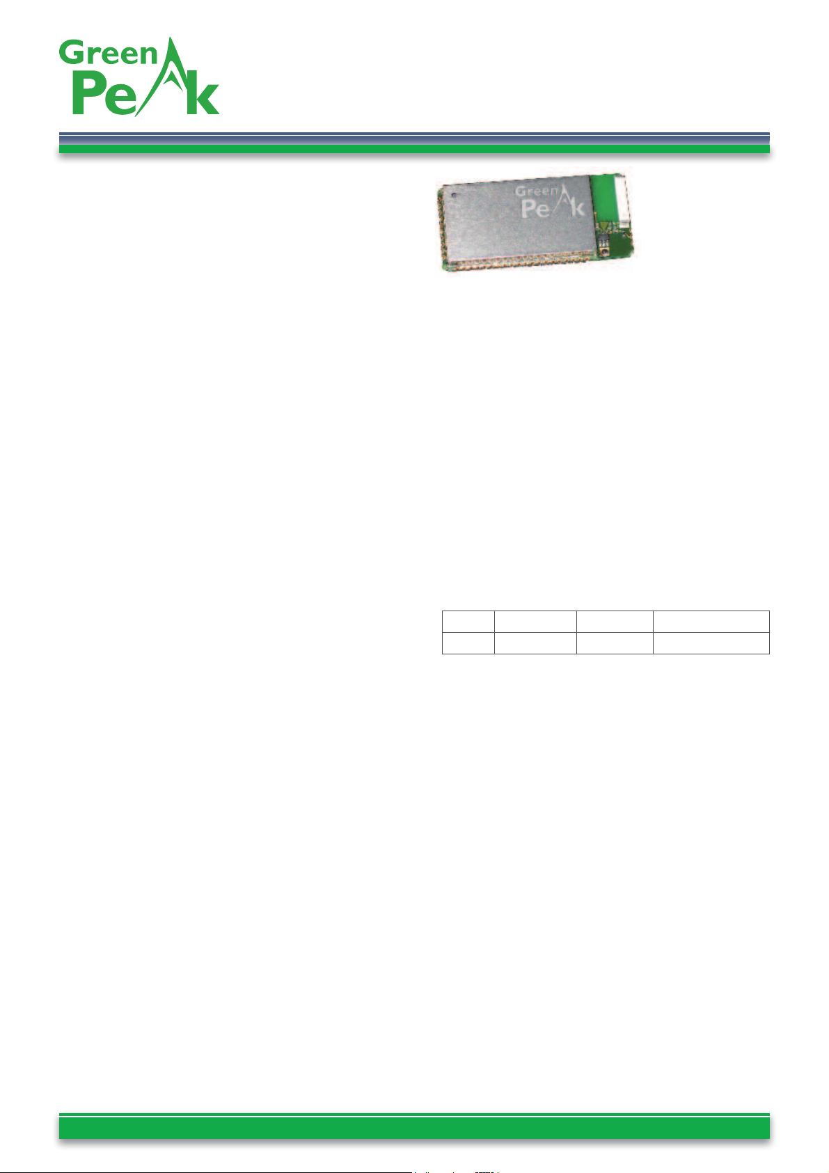
GreenPeak Lime CM09
High-performance wireless mesh network module
Specifi cations and information herein are subject to change without notice - Datasheet GreenPeak CM09 00575R1.09 - pag. 1
GreenPeak Lime Product Description
The CM09 is a high-performance wireless module
developed to provide the entire communications platform
of high-end mesh networks. The CM09 has all necessary
functions integrated in hardware and software to build
large, robust wireless mesh networks.
The CM09 is offered in two different versions, the
CM09CP, with on-board chip antenna, and the CM09XT,
provided with a provision for attachment of an off-module
antenna.
The features of the CM09 are aiming for at performance
critical applications requiring reliable and long-range
communication links. It also features a wide variety of
practical input and output functions.
The CM09 is designed for SMD-mounting onto a host PCB.
SMD-mounting provides the best RF performance at the
lowest cost. Additionally the CM09 is designed to occupy
minimal board space on the host PCB, which typically
already includes sensor/actuator interfacing circuits as
well as power conditioning circuits.
The CM09 operates in the 2.4 - 2.4835 GHz unlicensed,
worldwide ISM band, and is certifi ed to meet EN 300 328
(Europe) and FCC CFR47 Part 15 (US) standards.
Applications
Safety and security
Healthcare applications
Asset management
Building & home automation
Industrial automation
Versions
The CM09 modules support ultra-low-power applications,
in combination with long transmission range.
The CM09CP version features an on-module chip
antenna. It is ideally suited for all multi purpose wireless
mesh solutions.
The CM09XT version enables connecting the RF signal
to an external antenna. Ideally suited for all multipurpose
wireless mesh solutions that require specifi c, optimized
antenna performance, such as increased directivity and/
or extended ranges.
Radio Features
Radio: IEEE 802.15.4 compliant, operating in
2.4GHz worldwide ISM band
Channels: 16
Data rate: 250 kbps (PHY layer)
Antenna: chip antenna or external
Ultra-Low-Power: nodes can operate for years
without replacing batteries or can operate from
conditioned outputs of energy harvesting devices
Long range: extends range up to 100m indoors
and 1km outdoors for a single link
Communication range (in meters, typical and
max) measured with on-board ceramic antenna:
In the presence of blocking objects, range may be
shorter.
Indoor Outdoor Line-of-sight
Range 40-100m 160-400m 1000m
Additional Hardware Features
Designed for low-power: on-board power
management, including low-frequency clock source,
various power-down modes
Large amount of IO: 32 digital and analogue
IOs, including 8 channel 10 bit ADC, 2 UARTS, SPI,
JTAG
Cost optimized compact surface-mounted
module: only 35.5 by 16.5 mm, occupies only
a small board space, SMD technology eliminates
expensive connectors
Robust and compact design: the surface-
mountable module design facilitates robust, sturdy
and compact integration onto the mother board
Antenna fl exibility: available in 2 versions, with
choice between a compact on-board chip antenna
version or the version with optimized RF signal pads
for connection to an external antenna
Switchable power amplifi er - low power
mode
: allows to reduce TX power consumption if
there is no need for a power amplifi er
Page 2

Ultra Low Power Wireless Control Networks www.greenpeak.com
GreenPeak Lime CM09
High-performance wireless mesh network module
Specifi cations and information herein are subject to change without notice - Datasheet GreenPeak CM09 00575R1.09 - pag. 2
Mesh Communication Features
PeakNet™ Embedded Communication Software
All CM09 modules can be confi gured with a choice of two
different mesh network communication stacks: PeakNet™
Z or PeakNet™ LPR.
PeakNet™ Z
The features of this communication stack are:
Mesh network: messages travel from source
node to destination node through intermediate
nodes thereby multiplying range as a function of
number of hops. The multi-hop feature does not
require any application intervention.
Self-forming: mesh network forms automatically,
without any application intervention
Self healing: when individual links fail the mesh
network reestablishes a reliable route autonomously
Security: data transfer through message
encryption (AES 128 bit)
Support for mobile nodes: Nodes can
physically move through the network without
requiring network re-association
Support for ultra low power end devices:
Reduced functionality devices can operate for years
without replacing batteries
Support for network visualization: network
topology can be visualized using the optional
JadeMonitor PC software component
Robust against interference: able to operate
in the presence of other wireless devices such as
Wi-Fi, Bluetooth and others
Scalability: the network can scale up to 100s of
nodes without reconfi guration
GreenPeak™ provides embedded API to interface with
the PeakNet™Z communication stack
.
PeakNet™ Low Power Routing (LPR)
Instead of PeakNet™Z, the CM09 can be programmed
with the PeakNet™ Low Power Routing communication
stack as an option. PeakNet™ LPR is the industry’s fi rst
and most advanced (patented) communications stack
that supports mesh routing functionality with batteryoperated, or even battery-less, devices. Differentiating
features of this communication stack include:
Mesh network: all devices are low power routers
No distinction between RFDs and FFDs
Low power: no line-powered devices are required
All nodes can operate from batteries or energy
harvesters
Patented and smart power-up/power-down and
synchronization techniques enable all mesh nodes to
operate in a low-power mode
Complementary Products
In addition to industry leading modules, GreenPeak also
offers a full suite of development tools to assist OEMs in
designing systems using the CM09 and to build software
commissioning tools for the installer or end-user.
Please take a look at www.greenpeak.com for additional
information regarding:
Control Panel Builder: easy to use software
API exposing all network events (node association,
change of inputs,…) to a control panel
Embedded Interface Builder: use Standard
Interface Objects or build your own to interface
PeakNet™ seamlessly to your embedded application
JadeMonitor: graphical tool showing real-time
network status; can be included in any software
application
JadeConfi gurator: confi gure your mesh network
via a serial interface with a PC
JadeCreator: confi gure and update your mesh
network wirelessly
Energy Budget Calculator: powerful tool that
calculates the battery autonomy in applications
based on the PeakNet™ low power solution
Page 3
Ultra Low Power Wireless Control Networks www.greenpeak.com
GreenPeak Lime CM09
High-performance wireless mesh network module
Specifi cations and information herein are subject to change without notice - Datasheet GreenPeak CM09 00575R1.09 - pag. 3
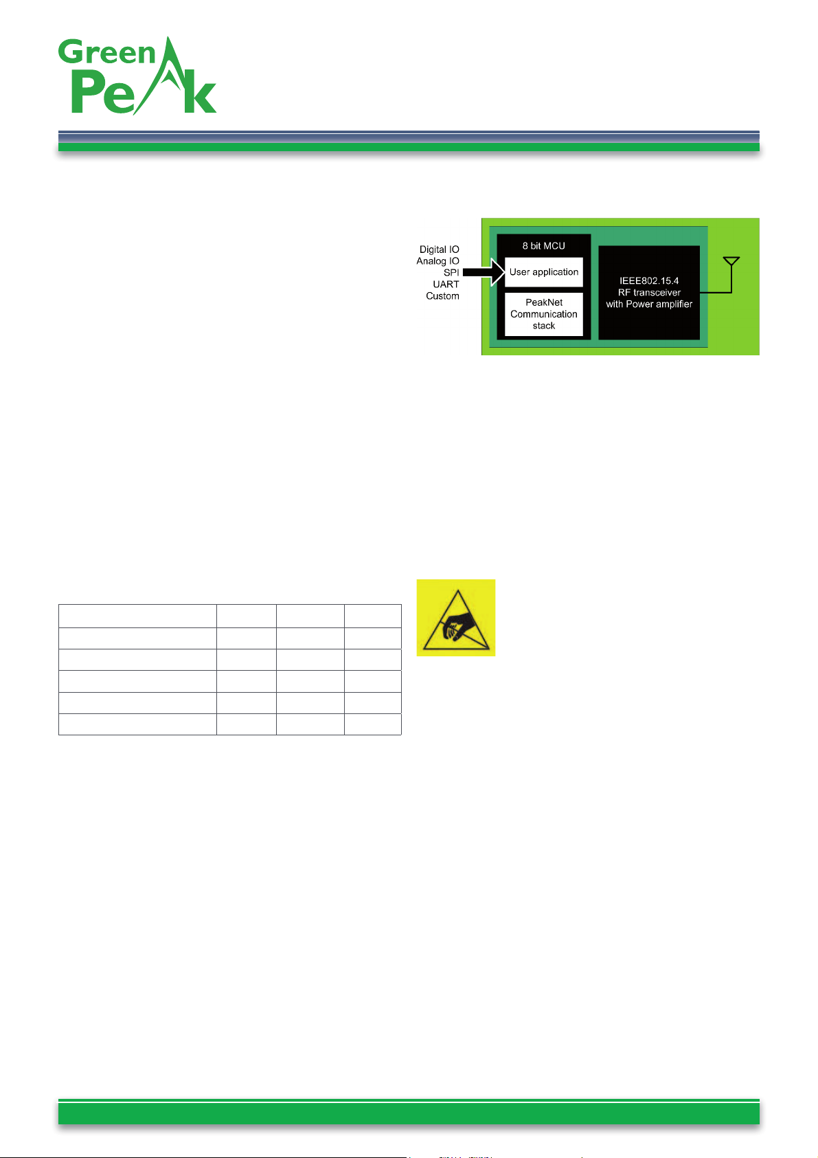
System Diagram
The module’s hardware consists of an IEEE802.15.4
compliant radio with power amplifi er & antenna and an
8-bit micro controller unit (MCU). The processor handles
the embedded software.
When the pre-programmed PeakNet™Z fi rmware with
the serial command set is on-board, the user application
will typically run on an external processor, confi guring
the module.
In case the embedded API is used, both the communication
stack and the customer’s application fi rmware are inside
the module. The user application interfaces with the
outside world through the IO ports on the module, analog
or digital IOs, UARTs, SPI.
Software can be updated through JTAG, ISP, UART or RF
interface.
Absolute Maximum Ratings
Parameter Min Max Unit
Supply voltage -0.3 3.6 V
Voltage on any pin -0.3 VCC+0.5 V
Input RF level 10 dBm
Storage temperature -50 150 °C
Operating temperature -30 85 °C
Caution !
ESD sensitive device.
Precaution should be used when handling the device in
order to prevent permanent damage.
Page 4
Ultra Low Power Wireless Control Networks www.greenpeak.com
GreenPeak Lime CM09
High-performance wireless mesh network module
Specifi cations and information herein are subject to change without notice - Datasheet GreenPeak CM09 00575R1.09 - pag. 4
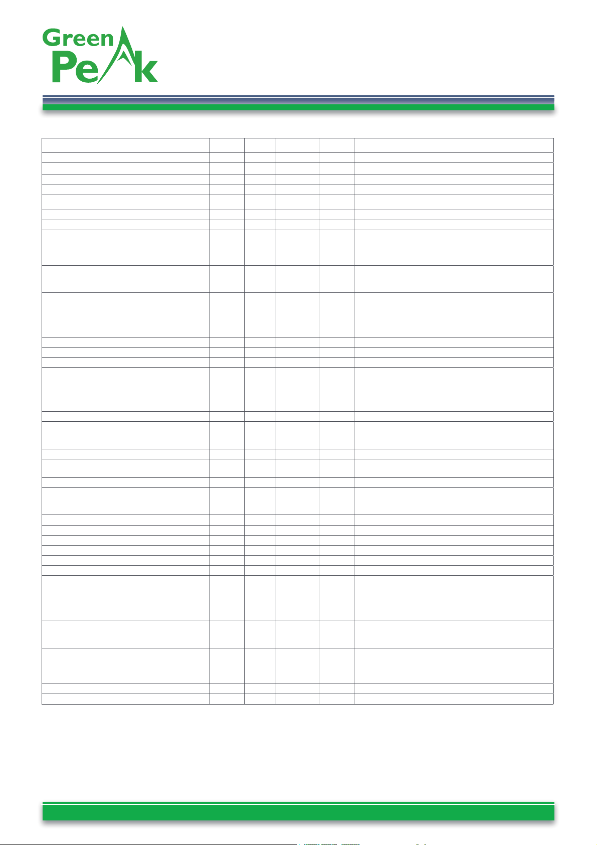
Electrical specifi cations
(1)
Parameter Min Typ Max Unit Condition
Operating frequency 2405 2480 MHz
Number of channels
(2)
16
Channel spacing 5 MHz
RF pin input/output impedance 50 Ohm
Bit rate 250 Kbit/s
DSSS chip rate 2 Mc/s
Frequency stability +/- 40 ppm
Transmit power
FCC
ETSI
(3)
Low-power mode
17
10
-7
dBm
Harmonics
2nd Harmonic
3rd Harmonic
-42
-42
dBm
EiRP
Spurious emission, Tx:
30-100 MHz
1-12.75 GHz
1.8-1.9 GHz
5.15-5.3 GHz
-36
-30
-47
-47
dBm Complies with EN 300 328, FCC CRF47 Part 15 and
ARIB STD-66
Sensitivity -92 dBm PER = 1%
Adjacent channel rejection +/- 5MHz 45/30 dB
Alternate channel rejection +/- 10MHz 54/53 dB
Blocking / desensitization
+/- 5 MHz from band edge
+/- 10 MHz from band edge
+/- 20 MHz from band edge
+/- 50 MHz from band edge
-28
-28
-27
-28
dBm Wanted signal 3dB above sensitivity level, CW interferer,
PER = 1%
Saturation (max. Input level) 0 10 dBm PER = 1%
Spurious emission, Rx:
30-100 MHz
1-12.75 GHz
-57
-47
dBm Complies with EN 300 328, FCC CRF47 Part 15 and
ARIB STD-66
Supply voltage 2.7 3.6 V
Supply voltage rise time 150 µs If appropriate rise time cannot be guaranteed, the RESET
pin should be activated after supply voltage is stable
Current consumption, Rx 30 mA
Current consumption
High power mode nPAEN=0 @ 13 dBm
Low power mode nPAEN=1
100
45
mA
Current consumption, Powerdown 1 µA
MCU fl ash memory 128 kByte
MCU RAM 8 kByte
MCU EEPROM 4 kByte
MCU clock frequency 8 MHz
MCU low frequency crystal 32.768 kHz
Digital IO
Input logic level, low
Input logic level, high
Output logic level, low (10 mA)
Output logic level, high (-10 mA)
0.5
0.6 VCC
0
2.4
0.3 VCC
VCC+0.5
0.5
3.0
V
Reset pin
Input logic level, low
Input logic level, high
-0.5
0.9VCC
0.1VCC
VCC+0.5
V
nPAEN
(4)
Input logic level, low
Input logic level, high
Internal pull down, input current at 3.3V
1.7V
90uA
0.4V
Power amplifi er is disabled at logic high
Internal RESET pull-up resistor 30 60 kOhm
1.8V regulated voltage at pin 29 1.7 1.8 1.9 V
(1) RF performance is measured in conducted mode unless stated
otherwise. All electrical performance data is measured at 25 degrees
Celsius and 3.3V Supply Voltage.
(2) IEEE 802.15.8 channel 26 is disabled on the FCC version of the
CM09 module.
(3) Power is measured in conducted mode. The gain of the embedded
antenna of the CM09CP module is 3dBi peak. In case of the CM09CP
for the ETSI domain the TX power is adjusted to stay within regulatory
limits (10dBm EiRP).
(4) To achieve the lowest leakage current in powerdown mode while
using active TX power control, it is advised to switch nPAEN to GND
before entering the powerdown mode. If the PA should be always
disabled, this can be achieved by connecting the nPAEN pin to the
VREF1.8V pin. The Leakage current in powerdown mode through
nPAEN will be zero because the VREF1.8V is 0V in powerdown mode.
In active mode VREF1.8V will be available again, so the PA will be
disabled.
Page 5
Ultra Low Power Wireless Control Networks www.greenpeak.com
GreenPeak Lime CM09
High-performance wireless mesh network module
Specifi cations and information herein are subject to change without notice - Datasheet GreenPeak CM09 00575R1.09 - pag. 5
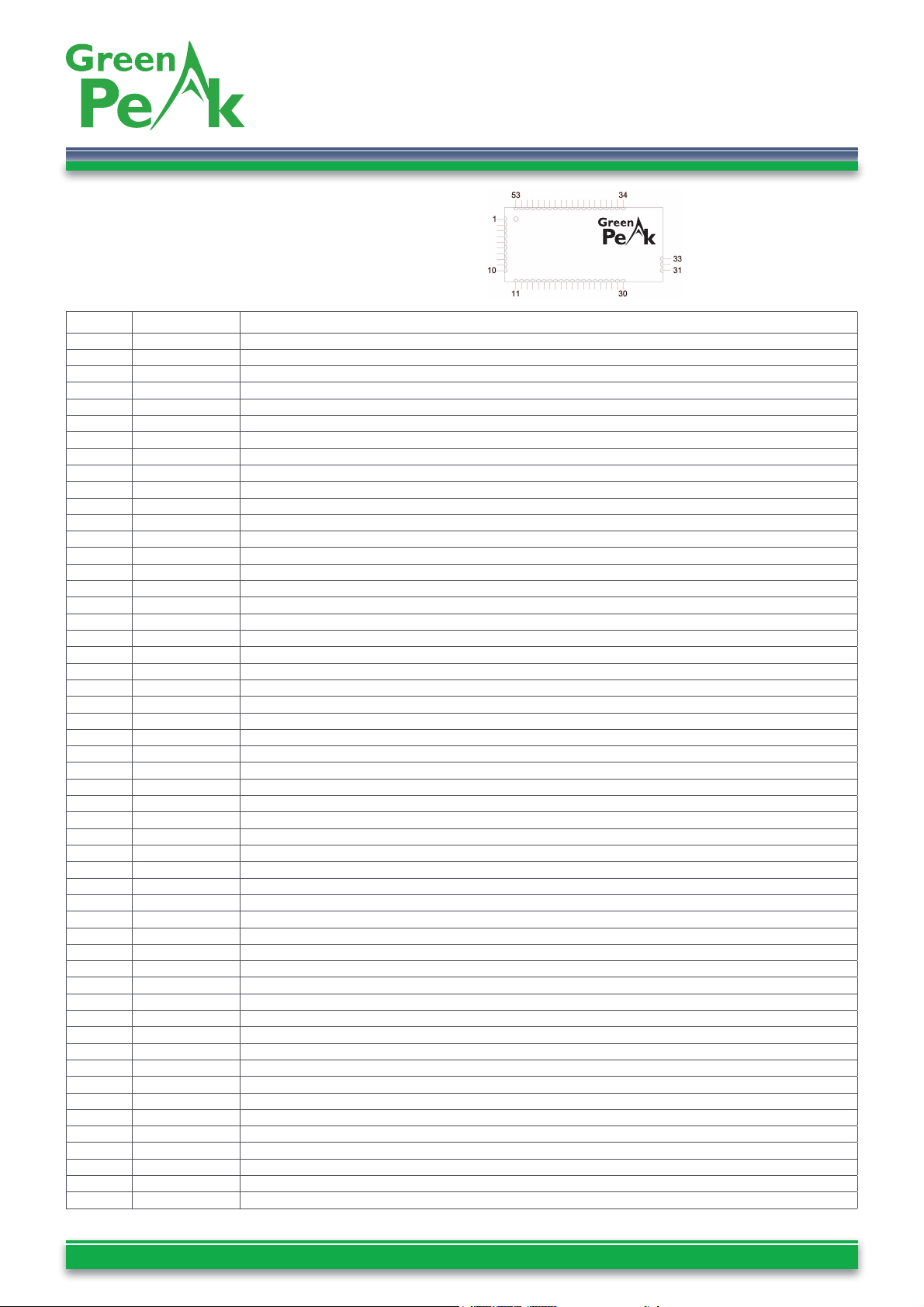
Pin Description
The pin list and its description is given in table below.
Pins are numbered from 1 to 53, pin 1 is indicated by an
opening in the shield can in upper left corner.
Pin no Pin name Description and Internal MCU Connection
1 GND System ground
2 VCC Supply voltage input
3 PG0 Digital I/O, PG0
4 nPAEN Power amplifi er enable: nPAEN = 0: High power mode / nPAEN = 1: Low power mode
5 PD7(CTS1) Digital I/O, PD7 / CTS1
6 PD5(RTS1) Digital I/O, PD5 / RTS1
7 PG2 Digital I/O, PG2
8 PD3(TXD1) Digital I/O, PD3 / TXD1 / INT3
9 PD2(RXD1) Digital I/O, PD2 / RXD1 / INT2
10 GND System ground
11 GND System ground
12 PF7/ADC7 Digital or analogue I/O, PF7, JTAG TDI
13 PF6/ADC6 Digital or analogue I/O, PF6, JTAG TDO
14 PF5/ADC5 Digital or analogue I/O, PF5, JTAG TMS
15 PF4/ADC4 Digital or analogue I/O, PF4, JTAG TCK
16 PF3/ADC3 Digital or analogue I/O, PF3
17 PF2/ADC2 Digital or analogue I/O, PF2
18 PF1/ADC1 Digital or analogue I/O, PF1
19 PF0/ADC0 Digital or analogue I/O, PF0
20 AREF Analogue reference voltage pin for the internal A/D Converter. Internally decoupled with 22nF.
21 PE0 Digital I/O, PE0
22 PE1 Digital I/O, PE1
23 PE2 Digital I/O, PE2
24 PE3 Digital I/O, PE3
25 PE4 Digital I/O, PE4 / INT4
26 PE5 Digital I/O, PE5 / INT5
27 PE6 Digital I/O, PE6 / INT6
28 PE7 Digital I/O, PE7 / INT7
29 1.8V Internally regulated voltage. Normally not connect. May be used for AREF
30 GND System ground
31 GND System ground
32 RF RF I/O connection to antenna, 50 Ohm. Do not connect for integrated antenna or connector variant.
33 GND System ground
34 GND System ground
35 PB0 Do not connect, internally used for CSn
36 PB1/SCLK SPI interface must be shared with MAC, ISP SCK
37 PB2/MOSI SPI interface must be shared with MAC, ISP MOSI
38 PB3/MISO SPI interface must be shared with MAC, ISP MISO
39 PB4 Digital I/O, PB4
40 PB5 Do not connect, internally used for VREG_EN
41 PB6 Do not connect, internally used for RESETn
42 PB7 Digital I/O, PB7
43 TOSC2 Internal 32.768 kHz oscillator
44 RESET Internal MCU reset. Active low with internal pull-up.
45 PD0 / INT0 Do not connect, internally used for DCLK / FIFOP
46 PD1 / INT1 Do not connect, internally used for DIO / FIFO
47 PD2/RXD1 Same as pin 9
48 PD3/TXD1 Same as pin 8
49 PD4 Do not connect, internally used for SFD
50 PD5(RTS1) Same as pin 6
51 PD6 Do not connect, internally used for CCA
52 PD7(CTS1) Same as pin 5
53 GND System ground
Page 6
Ultra Low Power Wireless Control Networks www.greenpeak.com
GreenPeak Lime CM09
High-performance wireless mesh network module
Specifi cations and information herein are subject to change without notice - Datasheet GreenPeak CM09 00575R1.09 - pag. 6
Component Reference Value Manufacturer Manufacturer Reference
C1 2.2uF Kemet C0402C225M9PAC
C4,C2 100nF Kemet C0402C104K4RAC
C2 33nF Kemet C0402C333K4RAC
C3 100 uF Kemet T495C107K006ATE150
C5,C7,C8,C9,C10 100 nF Kemet C0402C104K4RAC
C6 10uF Kemet B45025B1069K757
C12,C11 10nF Kemet T495C106K020ATE400
D1 RLED Avago HSMC-C150
D2 GLED Osram LGN971
J1 JTAG Samtec TSM-106-02-S-DV
P1 DCON Multicomp 5504F1-09S-01-03-F1
R2,R1 150R Multicomp 0402WGF1500TCE
R3, R4, R6 10k Multicomp 0402WGF1002TCE
R5 0R Multicomp 0402WGF0000TCE
SW1,SW2,SW3 SWITCH Omron B3FS-1052
U1 CM09 GreenPeak GPCM09XT
U2 LDO Micrel MIC5209_3.3BS
U3 RS232 Maxim MAX3221
X1 DC-JACK Cliff DC8 power socket
X2 SMA Jyebao SMA8402-0000
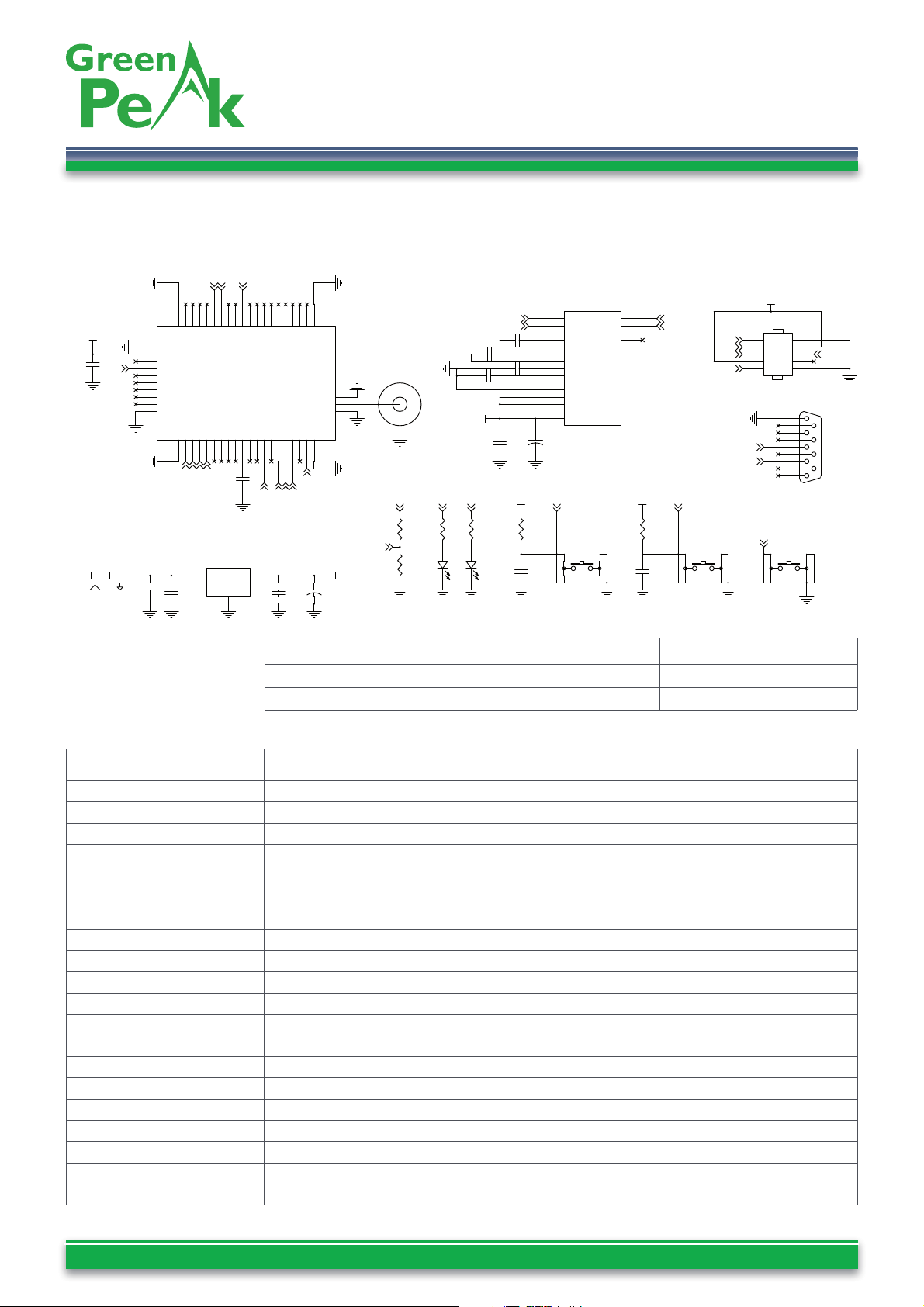
Application Circuit
An application example circuit is shown in fi gure 3.
Figure 3
R1
150R
R5
0R
C6
10uF
+
C7
100 nF
SW2
SW
1
4
2
3
C5
100 nF
SW1
SW
1
4
2
3
U2
MIC5209_3.3BS
IN1OUT
3
GND
2
C3
100 uF
+
C12
10nF
C10
100 nF
C2
33nF
P1
CONNECTOR_DB9
5
9
4
8
3
7
2
6
1
U1
CM09-XT
GND
1
VCC
2
PG0
3
nPAEN
4
PD7-1
5
PD5-1
6
PG2
7
TXD1/PD3-1
8
RXD1/PD2-1
9
GND
10
GND11PF7/TDI12PF5/TMS14PF4/TCK
15
PF316PF6/TDO13PF217PF019PE2
23
PF118AREF20PE021PE122PE425PE3
24
GND
31
PE526PE728PE6271.8V29GND
30
RF
32
GND
33
PB1/SCLK
36
PG3/TOSC2
43
PB7
42
PD7
52
PB3/MISO
38
PB5/VREG_EN
40
GND
53
PD6/CCA
51
RESET
44
PD0/FIFOP
45
GND
34
PD5
50
PB4
39
PB6/RESETn
41
PD1/FIFO
46
CSn/PB0
35
PB2/MOSI
37
PD4/SFD
49
RXD1/PD2
47
TXD1/PD3
48
C11
10nF
R4
10k
C8
100 nF
R2
150R
D1
RLED
R6
10k
J1
JTAG
2
4
6
8
10
1
3
5
7
9
R3
10k
C4
100nF
C9
100 nF
U3
MAX3221/SO
RIN
8
TIN
11
ROUT
9
INVALID
10
TOUT
13
C1+
2
C1-
4
C2+
5
C2-
6
V+
3
V-
7
EN
1
FORCEON
12
FORCEOFF
16
VCC
15
C2
100nF
SMA
X2
C1
2.2uF
D2
GLED
X1
JACK DC
3
2
1
SW3
SW
1
4
2
3
VCC_3.3V
VCC_3.3V
VCC_3.3V
VCC_3.3V
VCC_3.3V VCC_3.3V
TDO
TDI
TMS
TCK
nRESET
nRESET
PE6
PE5
PE4
PE2
TDI
TDO
TMS
TCK
PE6
PE4 PE5
nRESET
PD2
PD3
PD3
PD2
RXD
RXD
TXD
TXD
PE2
nPAEN
nPAEN
VREF1.8V
VREF1.8V
R5 R6 Function
Do not place 10k PA is enabled
0 Ohm Do not place PA is disabled
Page 7
Ultra Low Power Wireless Control Networks www.greenpeak.com
GreenPeak Lime CM09
High-performance wireless mesh network module
Specifi cations and information herein are subject to change without notice - Datasheet GreenPeak CM09 00575R1.09 - pag. 7
Antenna and Range Considerations
The CM09CP module is delivered with an integrated
antenna. This is highly recommended for most
applications, as this gives a very compact solution
containing all the critical RF parts within the module.
The radiation pattern from the antenna is similar to the
donut-shaped radiation from a quarter wave antenna. That
is, the maximum radiation is in the plane perpendicular
to the length axis of the antenna. For best possible omnidirectional radiation the module should be oriented so
that the antenna is vertical.
The antenna should be kept away (> 10mm) from
metallic or other conductive and dielectric materials.
Metallic enclosures shield the antenna and reduce the
communication range drastically. In applications where
the module must be placed in a metallic enclosure, an
external antenna gives best results. The signal for the
external antenna is available on the RF pin of the CM09XT
module. The RF input/output is matched to 50 Ohm.
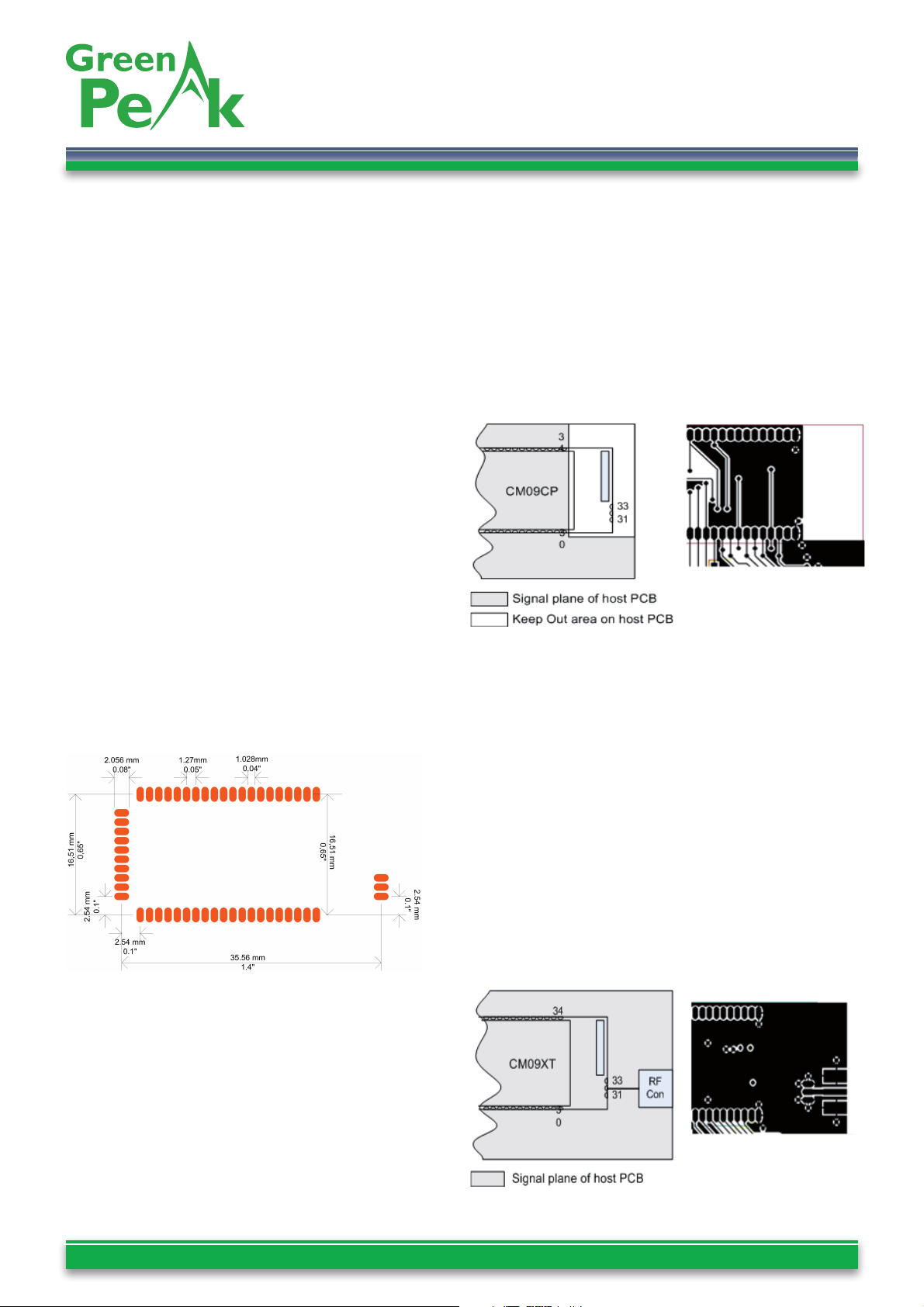
Chip Antenna Layout Recommendations
When using the module with on-board ceramic chip
antenna the area underneath the antenna should be kept
open, and if possible extended in east and north direction
as far as possible. Best possible placement of the module
on a mother PCB is in the north-east corner, as shown
in fi gure 4. Also with this module it is obligatory not to
solder pads 31,32 and 33. Figure 5 shows an example
the top layer the recommended layout.
Figure 5
External Antenna Layout Recommendations
In case of connecting an external antenna, the track
between the RF pin and the connector should be a 50
Ohm transmission line. The impedance of a transmission
line depends on the dielectric constant of the pcb
material, the trace width and the distance trace to
ground plane. GreenPeak recommends to calculate the
track width using a simulation tool. Such as AppCad
which is a free tool which can be downloaded form
http://hp.woodshot.com.
The top layer of a layout following the design rules is
show in fi gure 6.
Figure 6
Layout Recommendations
The recommended layout pads for the module are shown
in the fi gure 4. Dimensions are given in millimeter and
inches.
Figure 4
The area underneath the module should be covered with
solder resist in order to prevent short circuiting the test
pads on the backside of the module. A solid ground plane
under the module is preferred.
Each ground pin should be connected directly to the
ground plane. In case the ground plane is on an inner layer
of the pcb, via’s should be placed as close as possible to
every ground pad of the module to create low impedance
grounding. Unconnected pins should be soldered to the
pads, and the pads should be left fl oating.
Page 8
Ultra Low Power Wireless Control Networks www.greenpeak.com
GreenPeak Lime CM09
High-performance wireless mesh network module
Specifi cations and information herein are subject to change without notice - Datasheet GreenPeak CM09 00575R1.09 - pag. 8
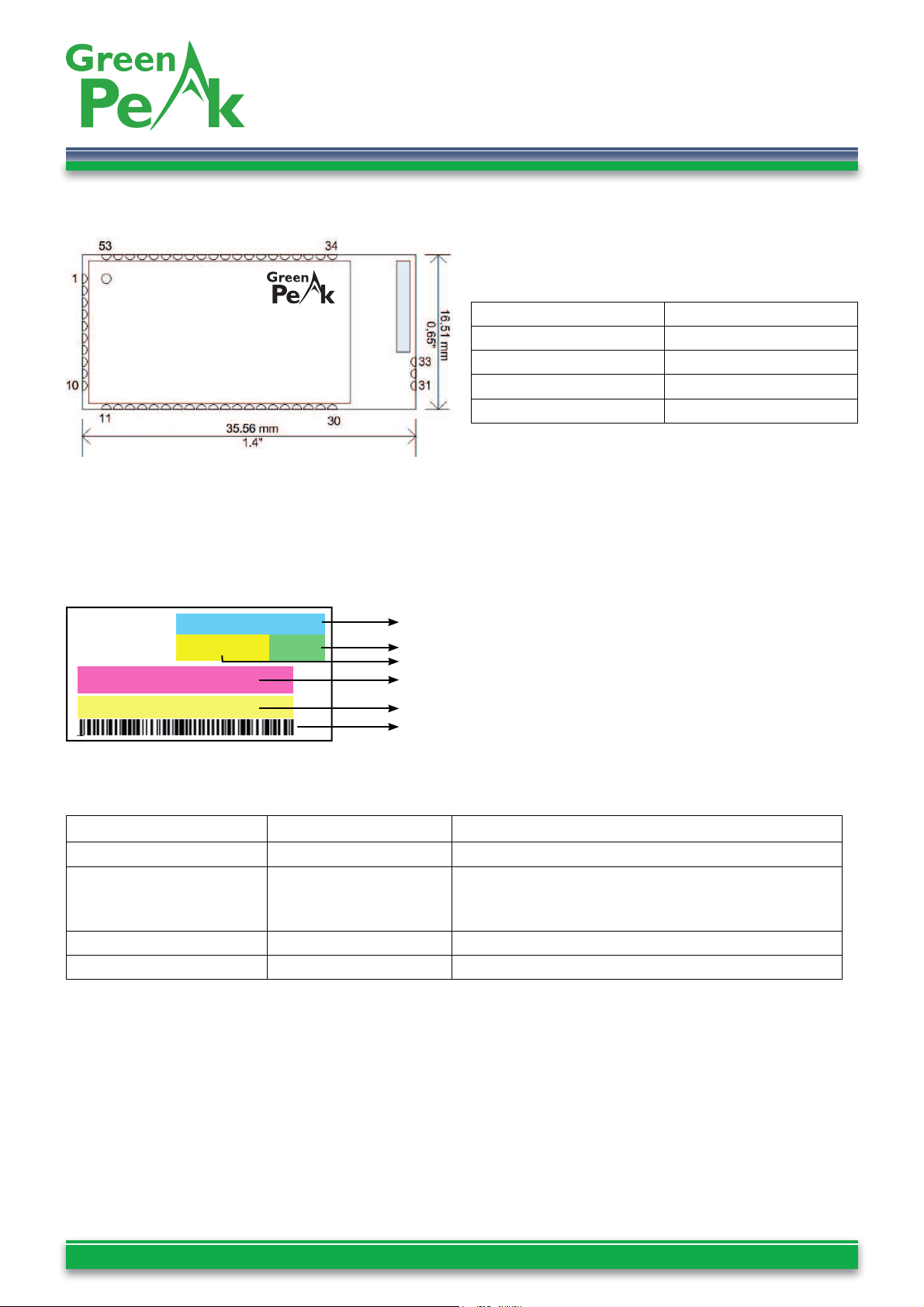
Mechanical Drawing and Dimensions
The module size is 0.65” x 1.4” x 0.14” (16.5 x 35.6 x
3.5 mm).
Carrier Tape and Reel Specifi cation
Carrier tape and reel is in accordance with EIA Specifi cation
481.
Tape width 56 mm
Component pitch 20 mm
Hole pitch 4 mm
Reel diameter 13”
Units per reel Max 800
RoHS Compliance
CM09 modules meet the requirements for RoHS
compliance.
Type number FCC ID Remark
CM09CPUS XFXCM09US Certifi ed with FCC Full modular approval
CM09XTUS XFXCM09US Certifi ed with FCC Full modular approval. The CM09XTUS
module is certifi ed as a FCC Transmitter Module with
3dBi maximum gain for the external antenna.
CM09CPEU n.a. Certifi ed with EN 300 328, complies with ARIB STD-66
CM09XTEU n.a. Certifi ed with EN 300 328, complies with ARIB STD-66
Identifi cation and label information
All modules are clearly labeled as in fi gure below.
CM09CPUS
K08510000D R 1.05
00155F000000245F
Module type number
Serial number
Revision number
FCC ID (only for US modules)
MAC Address
Barcode MAC address
FCC ID: XFXCM09US
Order/Regulatory Information
Page 9
Ultra Low Power Wireless Control Networks www.greenpeak.com
GreenPeak Lime CM09
High-performance wireless mesh network module
Specifi cations and information herein are subject to change without notice - Datasheet GreenPeak CM09 00575R1.09 - pag. 9
This equipment has been tested and found to comply with the limits for a Class
B digital device, pursuant to Part 15 of the FCC Rules. These limits are designed
to provide reasonable protection against harmful interference in a residential
installation. This equipment generates, uses and can radiate radio frequency
energy and, if not installed and used in accordance with the instructions, may
cause harmful interference to radio communications. However, there is no
guarantee that interference will not occur in a particular installation.
If this equipment does cause harmful interference to radio or television reception,
which can be determined by turning the equipment off and on, the user is
encouraged to try to correct the interference by one or more of the following
measures:
-- Reorient or relocate the receiving antenna.
-- Increase the separation between the equipment and receiver.
-- Connect the equipment into an outlet on a circuit different from that to which
the receiver is connected.
Consult the dealer or an experienced radio/TV technician for help.WARNING
If the FCC ID of the CM09 modules is not visible when the module is installed
inside another device, then the outside of the device into which the module is
installed must also display a label referring to the enclosed module.
This exterior label can use wording such as the following: “Contains Transmitter
Module FCC ID: XFXCM09US.”
WARNING
This device complies with FCC RF radiation exposure limits set forth for an
uncontrolled environment. The antenna used for this transmitter must be installed
to provide a separation distance of at least 20 cm from all persons and must not
be co-located or operating in conjunction with any other antenna or transmitter.
WARNING
This device complies with Part 15 of the FCC Rules. Operation is subject to the
following two conditions: (1) this device may not cause harmful interference,
and (2) this device must accept any interference received, including interference
that may cause undesired operation.WARNING
Changes or modifi cations to the equipment not expressly approved by the
party responsible for compliance could void the user’s authority to operate the
equipment.
WARNING
FCC Notice
Page 10

Ultra Low Power Wireless Control Networks www.greenpeak.com
GreenPeak Lime CM09
High-performance wireless mesh network module
Specifi cations and information herein are subject to change without notice - Datasheet GreenPeak CM09 00575R1.09 - pag. 10
Disclaimer
GreenPeak Technologies believes the information contained herein is correct and accurate at the time of this printing.
However, GreenPeak Technologies reserves the right to make changes to this product without notice. GreenPeak
Technologies does not assume any responsibility for the use of the described product; neither does it convey any
license under its patent rights, or the rights of others. The latest updates are available at the GreenPeak website or
by contacting GreenPeak directly.
As far as possible, major changes of product specifi cations and functionality, will be stated in product specifi c Errata
Notes are published at the GreenPeak website. Customers are encouraged to check regularly for the most recent
updates on products and support tools.
Life Support Policy
This GreenPeak product is not designed for use in life support appliances, devices, or other systems where malfunction
can reasonably be expected to result in signifi cant personal injury to the user, or as a critical component in any life
support device or system whose failure to perform can be reasonably expected to cause the failure of the life support
device or system, or to affect its safety or effectiveness. GreenPeak customers using or selling these products for use
in such applications do so at their own risk and agree to fully indemnify GreenPeak for any damages resulting from
any improper use or sale.
 Loading...