

Page 1

Baldwin™-Series
Model 5210D
Thermo-Electric Cooler
User’s Manual
Perma Pure LLC • A Halma Company • [email protected] • www.permapure.com
Telephone: 732-244-0010 • Toll Free: 800-337-3762 • Fax: 732-244-8140
1001 New Hampshire Ave., Lakewood, NJ 08701 USA
Page 2

CONTENTS
3. Introduction
6. Specifications
6. Connections
7. Important Safety Warnings
8. Installation
8. Hardware required for installation
8. Mounting
8. Connections
8. Sample and Drain
9. Board Connections
13. LED Summary
14. Start-up
15. Troubleshooting and Maintenance Guide
19. Replacement Parts
20. Appendix A: Cooler Drawings
20. A1: Model 5210D dimensional drawing
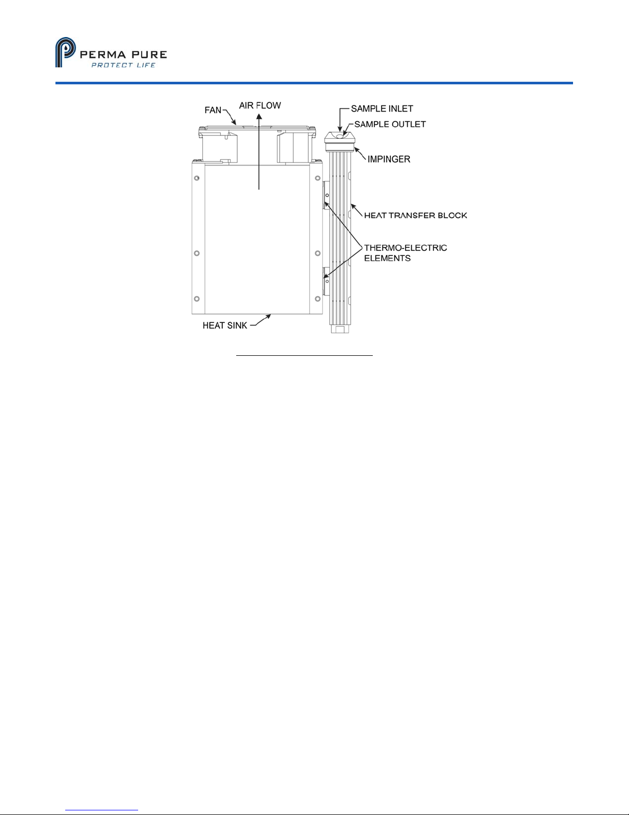
21. A2: Impinger diagram
22. Appendix B: Sample Conditioning System Drawings
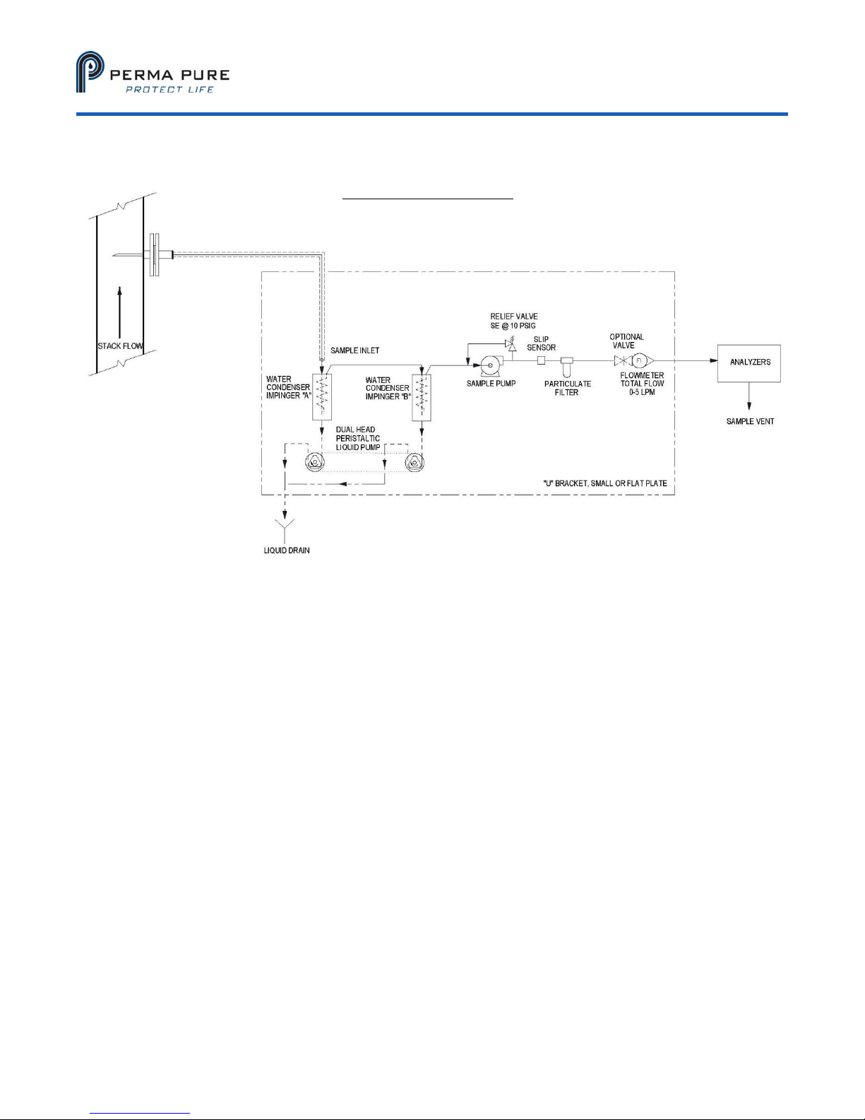
22. B1: Flow schematic
23. Appendix C: Conversion Table
25. Appendix D: Warranty and Disclaimer
Model 5210D User’s Manual
Doc. SE-MAN-050 REV 00
©2017 Perma Pure LLC. All rights reserved. Specifications subject to change.
Page 2 of 25
Page 3

Model 5210D User’s Manual
Doc. SE-MAN-050 REV 00
UNPACKING
Perma Pure has made every effort to ship you a high-quality product that has been thoroughly inspected and
tested. It has been carefully packed to ensure that it arrives at your facility in good condition. Even though every
effort has been made to prevent damage during the transportation process, damage can occur by the carrier. This
is out of control of Perma Pure and is the responsibility of the carrier to ensure that your equipment arrives intact
and undamaged.
Inspect outside packaging. If there is any visible damage, inform the carrier at the time of deliver. This
inspection is important! Once the package is signed for, responsibility for any visible damage then
transfers to the consignee.
Unpack your equipment. Visually inspect the outside of your equipment for any damage. If there is any
damage, contact the carrier immediately. Generally, a carrier must be notified within 24 hours of the delivery
to make a hidden damage claim.
Items in the carton include:
(1) Model 5210D thermo-electric cooler
(1) User’s Manual
Optional glass impingers will ship separately.
If any of the above parts are missing or damaged, call the helpline at (800) 337-3762.
INTRODUCTION
Thank you for purchasing this product from Perma Pure LLC. This manual has been assembled so that it can
answer all questions regarding operation. Please keep the operators manual near the equipment for future
reference. There may also be optional equipment available that was not ordered at the time of original purchase,
which may be described and/or illustrated in this manual.
If you still have any questions regarding your equipment’s operation, available options or technical support,
please contact your purchasing dealer or contact Perma Pure directly.
Perma Pure LLC Tel: 732-244-0010
1001 New Hampshire Ave. Tel: 800-337-3762 (toll free US)
Lakewood, NJ 08701 Fax: 732-244-8140
website: www.permapure.com e-mail: [email protected]
This equipment is to be installed and operated by trained personnel, with sufficient command of the English
language to clearly understand the instructions and safety warnings.
©2017 Perma Pure LLC. All rights reserved. Specifications subject to change.
Page 3 of 25
Page 4
Model 5210D User’s Manual
Doc. SE-MAN-050 REV 00
PRINCIPLE OF OPERATION
One of the natural products of combustion (and
other processes) is significant amounts of water
in the form of vapor. Most measurement
processes require this water to be removed for
proper measurement and/or reliability of the
system. The cooler rapidly lowers the
temperature of the sample stream in the impinger
to just above the freezing point of the water,
thereby forcing water vapor to condense. Once
condensed, it is collected and removed. The
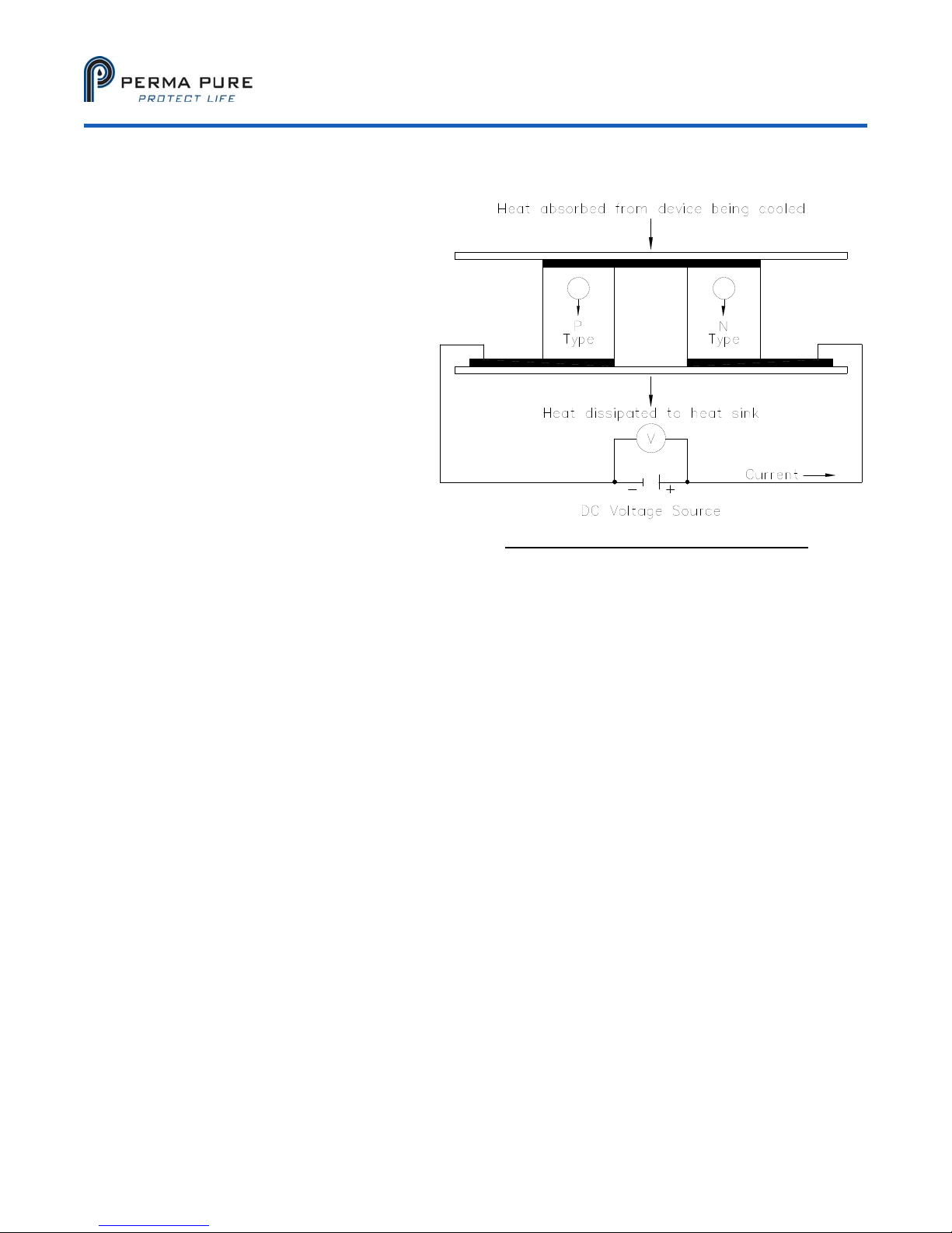
5210D is a thermoelectric cooler, which utilizes
TECs (also called Peltier elements) to provide
active cooling. The cooler may include a passive
stage, where the cold block is thermally mated
directly to the heat sink. The Peltier element is a
key element to this type of cooler. When
powered, one side becomes cold and the other
side becomes hot. The control system monitors
the coldest point on the heat transfer block, and
holds it to just above freezing, preventing the sample
Figure 1: Thermo-electric element (Peltier)
stream from icing up. The control system reacts to
variations in temperature at the heat transfer block, maintaining the set point as the load or ambient conditions
vary.
LIMITATIONS:
There are limitations to what a thermoelectric cooler can do. The Peltier elements can only move so much heat. If
more heat is applied to the channel than the element can move for a given set point, the element will be
overwhelmed and the temperature will rise above the set point. The Peltier element generates a differential
temperature for a given voltage and load. As the ambient temperature rises, the hot side heat sink rises with it.
Should ambient conditions become too hot the element will no longer be able to maintain the set point for the
applied load. Ambient conditions should be within specifications for proper operational characteristics. As
mentioned above, a cooler lowers the temperature of the sample stream to just above freezing. This process may
drop out other constituents of the sample stream with the water, some which may impact your measurements.
Perma Pure Provides Nafion-based sample conditioning systems which prevent loss of water soluble analyses
using a permeation method for sample drying.
©2017 Perma Pure LLC. All rights reserved. Specifications subject to change.
Page 4 of 25
Page 5
Model 5210D User’s Manual
Doc. SE-MAN-050 REV 00
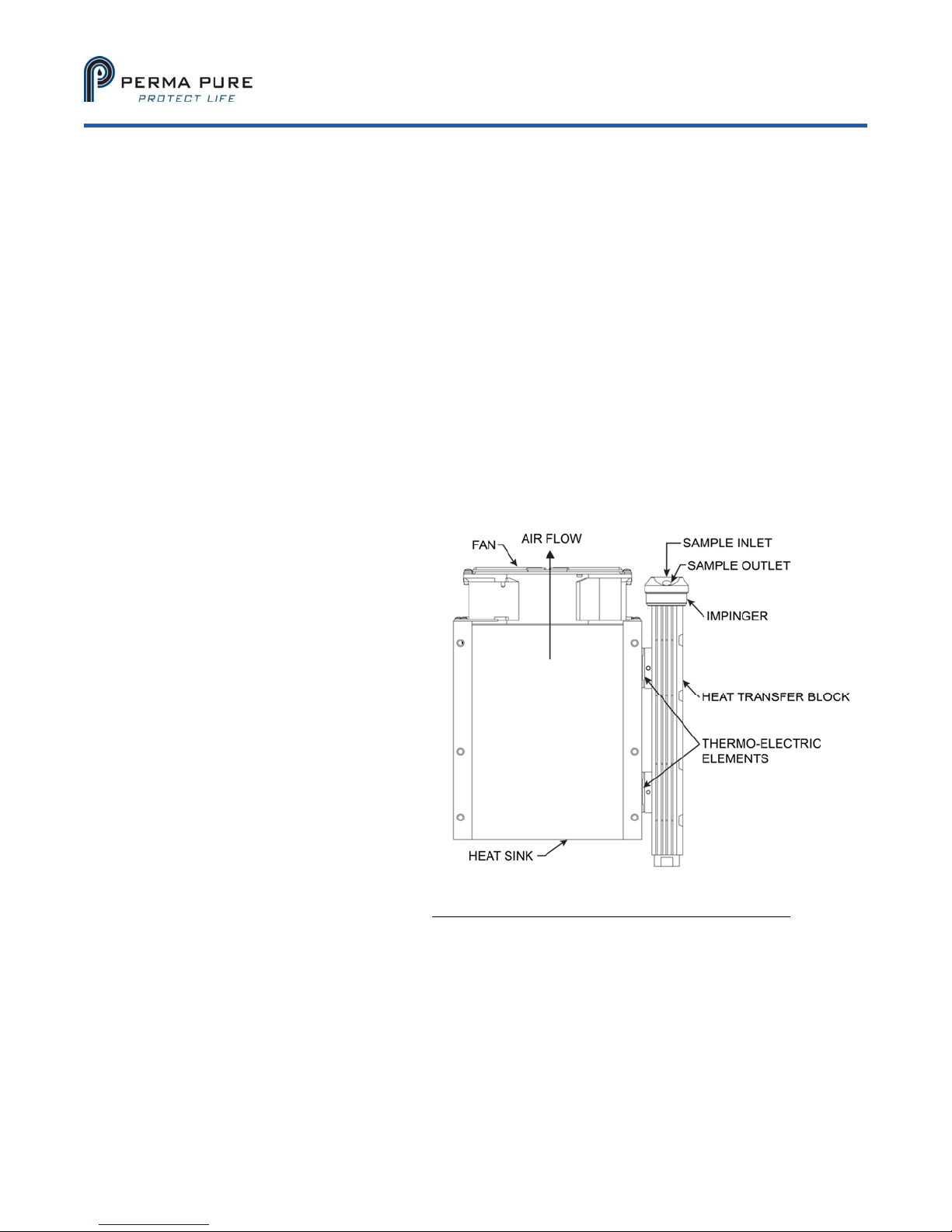
KEY COMPONENTS OF A THERMO-ELECTRIC COOLER:
1) Peltier Element: When DC voltage is applied to the Peltier element, one side of the element becomes
cold, and the other hot. This heating and cooling effect at the junction of dissimilar metals is referred to as
the Peltier effect, named after the physicist who discovered it in 1834. The Peltier elements used here are
very powerful, and if not properly mated to a thermal sink will get extremely hot very quickly. DO NOT
POWER these elements without proper connection to a heat sink! You may get burned, and will damage
or destroy the element!
2) Heat Sink: The Peltier elements generate a significant amount of waste heat when in operation. This
heat is conducted into a heat sink to be removed into the ambient environment by forced convection.
3) Heat Sink Fan: The above mentioned forced convection.
4) Heat Transfer Block: This is the mechanical and thermal interface between the cold side of the Peltier
elements and the walls of the impinger. The heat transfer block provides a conductive path and
mechanical interface between the long cylindrical impinger and the rectangular Peltier elements.
5) Impinger: Interface between the sample stream and the heat transfer block. Water vapor condenses
along the outer wall and collects in the bottom for extraction. The sample stream travels through the
impinger, so corrosion resistance must be considered.
6)
Power Supply: AC to regulated DC to provide sufficient amperage for the Peltier elements configuration.
Peltier elements have a very specific
power to performance curve.
Performance can be adversely
affected by supplying too much
power. The power supply provided is
factory adjusted, and should not be
altered!
7) Control Thermistors: Measures
temperature of the heat transfer
block at the Peltier element interface
for feedback to control electronics.
This is the temperature displayed,
and is the coldest point on the heat
transfer block.
8) Control Electronics: Regulates
power supplied to Peltier elements to
maintain a set temperature. The
control electronics provides Pulse
Width Modulated (PWM) power to
the Peltier elements, regulated by a
control loop.
9) Peristaltic Pump (not covered
here): Removes condensate from
the impinger without creating a path
Figure 2: Heat Exchanger, Impinger and Heat Sink
for outside air to enter the sample stream.
©2017 Perma Pure LLC. All rights reserved. Specifications subject to change.
Page 5 of 25
Page 6

Model 5210D User’s Manual
Doc. SE-MAN-050 REV 00
PHYSICAL DESCRIPTION
Single (Series) or Dual (Parallel) stream system
1 x 10” heat exchanger connected in series; actively cooled to the temperature set point
1 x 10” heat exchanger connected in series; passively cooled by direct contact with the heat sink
LCD temperature display
Dimensions: 14.5” x 11” x 10.5” HWD (37 x 28 x 26.5 cm)
Weight: 35 lbs (16 kg)
SPECIFICATIONS
Sample gas flow range Up to 8 LPM (Up to 17 SCFH)
Avg. inlet dew point at rated flow 20% H
O (60°C DP) @ 5 LPM
2
Maximum cooling rate 440 BTU/hr (464 kJ/hr)
Maximum inlet sample temp. 400°F (205°C) for SS or glass impingers
280°F (138°C) for Kynar™ impingers
Maximum inlet pressure 15 psig (1 bar;760 mmHg)
Maximum pressure drop <+1 in H2O
Ambient temperature range 33-104°F (0.6-40°C)
Outlet sample gas dew point 39°F (4°C)
Voltage
115 OR 230 VAC (Verify before energizing
equipment) 50/60 Hz
Power supply 600 Watt
Cooling down time Less than 6 minutes
CONNECTIONS
Sample gas inlet: Kynar, 3/8” tube compression fitting
Sample gas outlet: Kynar, 1/4” tube compression fitting
Drain tubing connection: Kynar, ¼” barbed tube fitting
An automatic condensate drain, dual-head peristaltic drain pump is recommended (not included) for
water removal, Perma Pure part number 3KPB-003; size 17 tubing.
Always use factory supplied fittings; Perma Pure cannot warrant against damage to the Peltier elements or heat
exchangers if our fittings are not used.
©2017 Perma Pure LLC. All rights reserved. Specifications subject to change.
Page 6 of 25
Page 7

Model 5210D User’s Manual
Doc. SE-MAN-050 REV 00
IMPORTANT SAFETY WARNINGS
Please be sure to review the following basic safety procedures. These procedures represent the MINIMUM
requirements to operate the equipment safely. It is the ultimate responsibility of the operator to ensure
that proper safety practices are utilized at the point of operation.
NEVER attempt to operate this equipment in an explosive or otherwise hazardous area.
NEVER exceed any specified rating for the equipment. Voltage, temperature and pressure ratings must be
closely observed and not exceeded. Voltage rating of the equipment MUST match the rating on the data
label. Please make sure that it matches before powering up the equipment.
This equipment is NOT designed to be used in an explosive environment.
This equipment is NOT designed to operate in a wet environment.
Condensate is potentially dangerous. NEVER handle drain lines, impingers or any other item that may
have come into contact with the gas stream or any hazardous material, without adequate personal protective
equipment. ALWAYS assume that any liquid present is hazardous.
Sample gas is potentially dangerous. A leak test is recommended at initial startup and as often as
necessary to maintain a safe working environment around the equipment. The gas stream exhaust must exit
away from all personnel to prevent dangerous exposure.
NEVER operate the equipment with any part of the enclosure unsecured. All operating doors and
covers must be in place and secured prior to operation. Electrical current may be present behind covers or
doors, even if tools are not necessary to access these components.
NEVER attempt service on this equipment without first disconnecting all energy sources. Repair of this
equipment should only be done by properly trained personnel that are familiar with the potential risks
involved with servicing of the equipment.
NEVER replace fuses with types other than the sample specification of type and current. Do not bypass this
or any other safety device.
NEVER operate this equipment if it is visibly damaged or the possibility exists that it may have been
damaged.
The use of components that have not been purchased through an authorized Perma Pure dealer or directly
from Perma Pure may compromise the safety of the operator. Additionally, use of non-authorized
components may change the operating characteristics of this equipment. Any changes to the equipment, that
modify its operation in any way, are dangerous, and are strictly prohibited.
Read the entire operating manual before attempting to set up or operate the equipment.
Please heed all warning labels that are on the equipment. They are there to remind you of possible
hazardous conditions.
Verify the integrity of any mechanical and/or electrical connections that are made to the unit.
Verify that the unit is connected to the proper rated power for the system
Verify that the unit is plumbed properly to operate effectively
©2017 Perma Pure LLC. All rights reserved. Specifications subject to change.
Page 7 of 25
Page 8
Model 5210D User’s Manual
Doc. SE-MAN-050 REV 00
INSTALLATION
Hardware required for installation
(4) ¼-20 mounting screws
For stainless steel sample lines, 2 inches of 3/8” Teflon tube
Peristaltic drain pump, dual head
Mounting
The Classic Model 5210D Thermo-Electric Cooler should be installed away from heat sources in a well
vented area.
NOTE: The operational stability of the cooler dew point is influenced by the stability of the
ambient temperature.
For proper operation, the ambient temperature cannot exceed 40°C (104°F). At, or close to the maximum
ambient temperature, the cooler will not be able to control the temperature to reduce the dew point of the
sample gas to the 4°C set point. This will result in compromised operation and water slip or carryover,
possibly into the analyzer. Also, at or near this temperature, the cooler will be running “full on” and Peltier
life will be greatly reduced.
CONNECTIONS
Sample and Drain
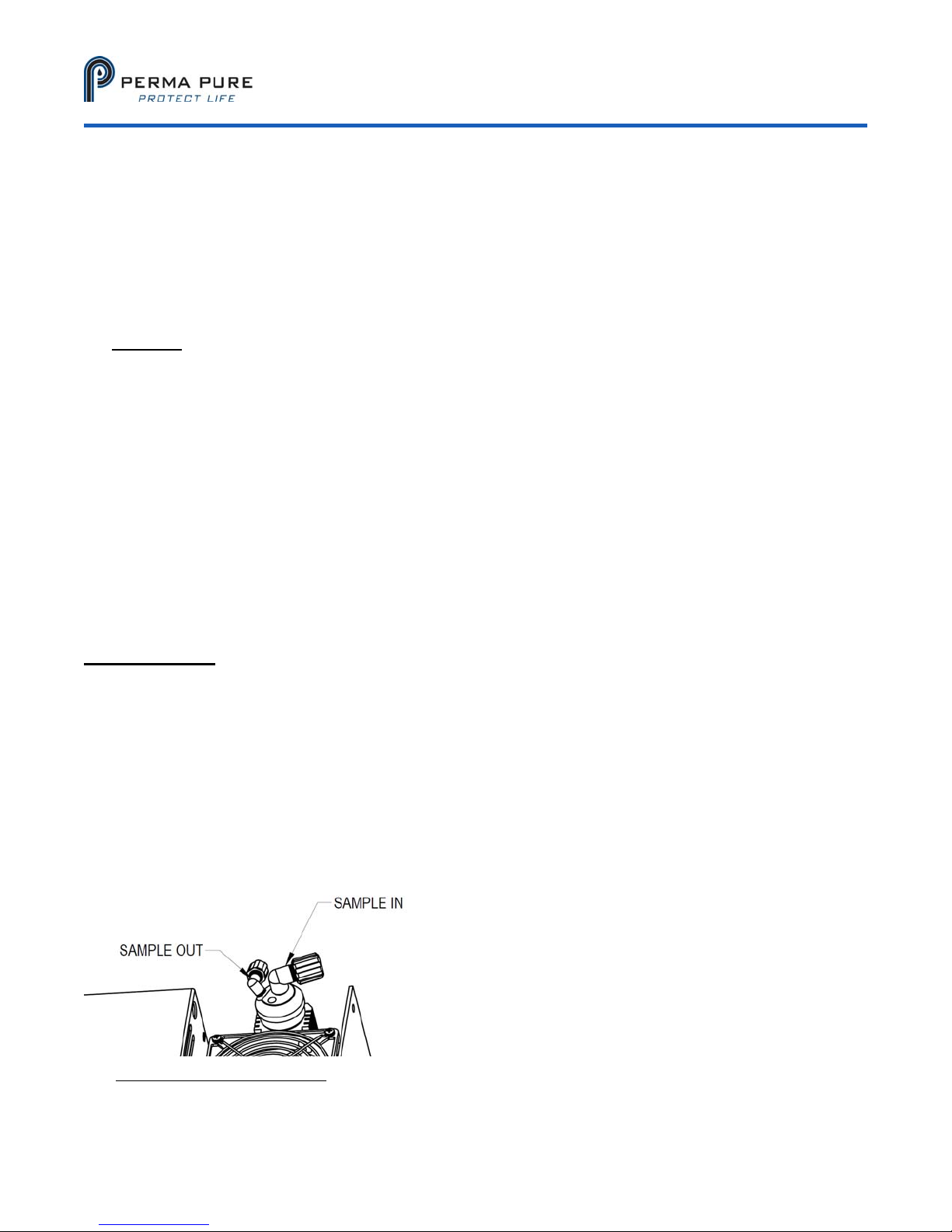
1. Connect the sample inlet to the 3/8” tube fitting shown in figure 3 below.
NOTE: If using heated stainless steel sample line, add 2 inches of Teflon tubing at the heat exchanger
inlet fitting, and connecting it to the heated line. This isolates the heated line from the heat exchanger
and prevents excessive heating of the heat exchanger, possibly overloading the cooler.
2. Connect the sample outlet to the 1/4” tube fitting shown in the figure.
3. Connect the peristaltic pumps to the ¼” barbed tube fittings at the base of the impinger.
NOTE: Do not reduce the size of the condensate tubing since doing so restricts water flow resulting in
water carryover into the sample.
Figure 3: Model 5210D Cooler
©2017 Perma Pure LLC. All rights reserved. Specifications subject to change.
Page 8 of 25
Page 9
BOARD CONNECTIONS
Model 5210D User’s Manual
Doc. SE-MAN-050 REV 00
©2017 Perma Pure LLC. All rights reserved. Specifications subject to change.
Page 9 of 25
Page 10
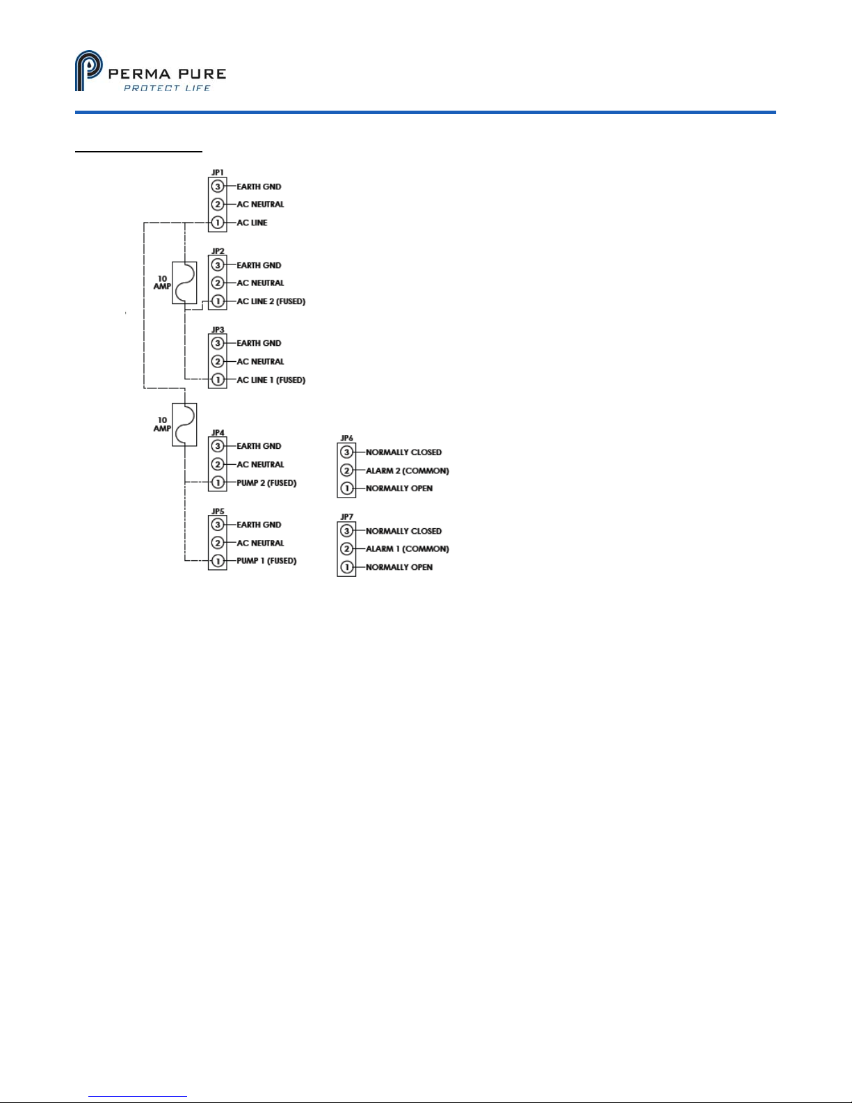
AC side (right side)
Model 5210D User’s Manual
Doc. SE-MAN-050 REV 00
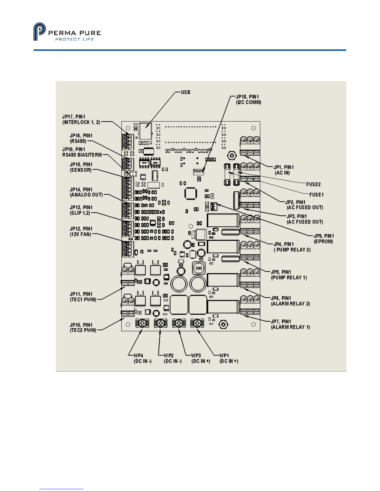
JP1: AC line in for accessory control.
JP2: Fused power out from JP1, currently heatsink fan.
JP3: Fused power out from JP1
JP4: Fused pump relay for Channel 2. Relay applies power to circuit when temperature is
below “ready” temperature. Circuit will open when temperature is above the ready
temperature. This avoids passing vapor exceeding the “ready temperature” dew point.
JP4 and JP5 operate independently of each other.
JP5: Fused pump relay for Channel 1. Relay applies power to the circuit when temperature is
below “ready” temperature. Circuit will open when temperature is above the ready
temperature. This avoids passing vapor exceeding the “ready temperature” dew point.
JP4 and JP5 operate independently of each other.
JP6-L Channel 2 alarm relay. Isolated relay which can be wired Normally Open (N.O.) or
Normally Closed (N.C.). JP6 and JP7 operate independently of each other. A sensor
failure (short or open) will trip the relay.
JP7: Channel 1 alarm relay. Isolated relay which can be wired NC or NO (normally open or
normally closed). JP6 and JP7 operate independently of each other. NOTE: The board is
incorrectly physically labeled.
FUSE1: 10Amp fuse between JP1 and JP2 and JP3
FUSE2: 10 Amp fuse between JP1 and JP4 and JP5 (pump relay controlled)
©2017 Perma Pure LLC. All rights reserved. Specifications subject to change.
Page 10 of 25
Page 11
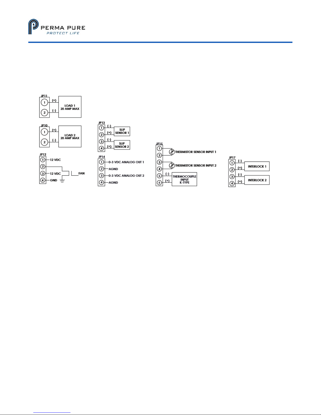
DC Side (left side):
Model 5210D User’s Manual
Doc. SE-MAN-050 REV 00
JP8: Not Used
JP9: EPROM flash. For factory use only.
JP10: Outputs for Peltier element channel 2. Pulse width modulated (PWM) with DC input voltage.
JP11: Outputs for Peltier element channel 1. Pulse width modulated (PWM) with DC input voltage.
JP12: 12VDC regulated out for fans. 2 Circuits, steady on and thermostatically controlled provided.
Thermostat control is for enclosure fan only
JP13: Slip sensor inputs. When resistive threshold is exceeded, pump relays open. Settings are
configurable via software.
JP14: Analog out, 0-3VDC. 2 channels are available. Each output can be configured to telemeter CH1
temp, CH2 temp, or TC temp, via manufacturer’s configuration software at time of purchase.
0VDC and 3VDC temperatures (for scaling) are selectable via configuration software.
JP15: Temperature sensor inputs for CH1 and CH2 thermistors and Type K thermocouple. NJTC MUST
be enabled via software. (Negative lead wire is red)
JP16: RS485 output. Not supported at this time.
JP17: Interlock inputs. When enabled in software, opening the interlock circuit disables the pump on
that channel. That is, the pump will not run unless the circuit is closed.
JP18: Expansion port. Not supported at this time.
JP19: RS485 bias and termination. Not supported at this time.
©2017 Perma Pure LLC. All rights reserved. Specifications subject to change.
Page 11 of 25
Page 12

Model 5210D User’s Manual
Doc. SE-MAN-050 REV 00
BASIC OPERATION
Your cooler comes from the factory ready to go, preset to operate at 4°C, and to close the sample pump relays at
10°C. Closing the pump relays illuminates the READY status LED, near the temperature display
interconnection diagram for a typical installation that includes water slip sensing, using cooler controlled pump
relays, interlock input and alarm relays. Your cooler can be operated without using any of these on-board
features.
. See the
CONTROLLER:
This cooler is controlled by a digital control board.
Throughout this manual, channel 1 refers to the left channel when facing the display, and channel 2 to the right.
This board regulates power to the Peltier elements to maintain the set point temperature regardless of the thermal
load on the channel (within the specified ranges). The board is capable of independently controlling two separate
channels. The board provides a pulse width modulated power output to the Peltier elements as determined by a
temperature control loop.
In addition, this board includes fused sample pump relays, alarm relays, 0-3V analog output, New Jersey
thermocouple input and output, and slip sensor electronics.
This controller is digitally controlled and configured using a PC via USB and proprietary software.
THE DISPLAY
The display operation varies depending on as shipped configuration. When the unit powers on, it will briefly
display R-XX (r-01, r-02, etc.). This is the revision of the control software loaded into the on-board memory.
©2017 Perma Pure LLC. All rights reserved. Specifications subject to change.
Page 12 of 25
Page 13
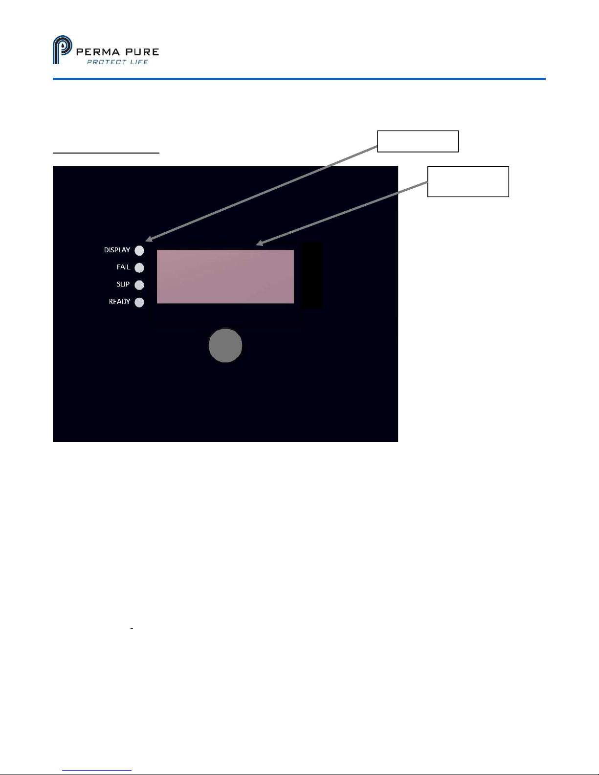
LED SUMMARY
Model 5210D User’s Manual
Doc. SE-MAN-050 REV 00
ForaDualChannelcooler:
Status LED’s
Temperature
Display
Single channel cooler (5210)
1) Numeric Display: Four digit LED display can show temperature in degrees Celsius of CH1 or NJTC.
2) Status LED’s: Indicate operational status of the system.
a. DISPLAY (Display state): GREEN indicator, flashing indicates cold block temperature, solid
indicates that NJTC is displayed.
b. FAIL (Failure): RED indicates that the controller has detected an internal system failure.
c. SLIP: GREEN indicates that the Water Slip sensor (if installed) has NOT detected water in the
sample stream. GREEN indicates that the slip controller has not disabled the sample pump(s).
d. READY: GREEN indicates the system has reached its cold ready point and has closed the pump
relays.
3) DISPLAY SELECT Button: Sets the display state. Pushing this button will toggle the display between
(flashing) CH1, NJTC (solid). The controller will not respond to features that are not enabled. For
example, if a NJTC is not enabled, the unit will not allow NJTC display as an option, it will instead display
the revision status. Enabling features in software that are not physically installed may cause unexpected /
unpredictable results.
Page 13 of 25
©2017 Perma Pure LLC. All rights reserved. Specifications subject to change.
Page 14

Model 5210D User’s Manual
Doc. SE-MAN-050 REV 00
START-UP
1. Verify AC power matches operating voltage that is specified on serial number data label.
2. Plug power cord into a properly grounded main circuit. Green “Slip” LED will come on.
3. Wait for the green “Ready” LED light to come on. This will indicate the impinger temperature is below
10°C and the sample gas flow can begin.
4. Afterwards the factory set-point of +4°C (41°F) will be reached.
The SLIP Green LED is always on unless;
Moisture is detected by the water slip sensor
There is a malfunction (e.g. Shorted water slip sensor leads or a defective relay)
©2017 Perma Pure LLC. All rights reserved. Specifications subject to change.
Page 14 of 25
Page 15

Model 5210D User’s Manual
Doc. SE-MAN-050 REV 00
TROUBLESHOOTING AND MAINTENANCE GUIDE
Troubleshooting and repair should only be attempted by qualified personnel;
Review Safety Warnings Page for more complete details of potential hazards
Inside the enclosure there are lethal AC voltages, 15VDC power at 12 amps, as well as exposed rotating fan
blades and other potentially hazardous components.
ALWAYS USE CAUTION! DEENERGIZE EQUIPMENT PRIOR TO ATTEMPING SERVICE!
The status board will indicate what the on-board computer thinks is happening.
Verify that the unit has commanded the response before going in to verifying hardware. For example, verify the
board indicates that the pump relay is closed before physically pulling the relay.
Peltier Elements
Troubleshooting Peltier elements can be difficult at the part level without specialized equipment. A conventional
Ohm Meter will not provide useful information. Peltier failure or degradation can be indicated by
current measurement. The measurement should be made during the first few minutes of start-up. For a 5210D,
the Peltier elements are wired in parallel, with each drawing between 6 and 9 amps. Unit-to-unit variation, such as
exact voltage, wire run length, ambient temperature, and cooler temperature, can generate some variation. This
test can also be performed by placing a DC inductive ammeter around the black or white leads coming off JP10 or
JP11.
12VDC Cooling Fan
There are two regulated outputs for the 12VDC cooling fans, one is thermostatically controlled by the control
board for enclosure component cooling. The 12VDC cooling fans on a 5210D should be wired to the designated
12VDC output of the board. Care should always be taken to avoid rotating blades!
©2017 Perma Pure LLC. All rights reserved. Specifications subject to change.
Page 15 of 25
Page 16

Symptom Diagnostic Fix
No LED(s) and no fan.
AC power input.
10A DC fuse on Control Board
15A AC Input fuse on Power
Supply
Verify 15VDC at output terminals
on Power Supply
LED(s) on and heatsink fan
does not run.
Check fan for blockage (power
off). Check for power at JP1 (AC
power input, unfused), JP2 (AC
power for fan, fused) on control
board
Verify voltage at terminal JP2 of
control PCB; Should be line
voltage
F1 on control PCB keeps
blowing.
Disconnect JP2 wiring for heat
sink fan; Replace fuse
Model 5210D User’s Manual
Doc. SE-MAN-050 REV 00
Ensure that AC power is connected.
Replace fuse as necessary.
Verify current draw is not
close to or exceeding fuse
rating
Verify current draw of Peltier
Elements
Replace control board if
Peltier elements test properly
and current is excessive
Replace fuse as necessary.
Verify current draw is not
close to or exceeding fuse
rating
Replace power supply if
current is excessive
If reading lower than 15VDC,
carefully disconnect wiring
and measure voltage
If not 15VDC, within 1.0VDC
adjust and/or replace
defective Power Supply
Clear any blockage, replace fuse or
repair wiring as required
Check fuses on control PCB-
If fuses are good and voltage
is not equal to line voltage,
replace control board.
If fuse1 is blown (open),
disconnect JP2 wiring for
heat sink fan and replace
fuse; Retest; reconnect wiring
if fuse does not blow
If fuse blows again, Fan or
wiring may be defective
Energize cooler and see if fuse blows-
Fuse blows-Replace control
PCB
Fuse does not blow-verify
heat sink fan wiring condition
If wiring is good, fan likely
defective
©2017 Perma Pure LLC. All rights reserved. Specifications subject to change.
Page 16 of 25
Page 17

Failure LED is on. Thermistor connection JP15 pins
1-4
Impinger frozen and cooler
indicates ambient
temperature.
Impinger does not reach set
temperature, but is below
ready temperature.
Thermistor placement in heat
exchanger block.
Peltier element wiring
System loading.
Verify Peltier Element current
draw
Ready LED does not come
Ready temperature adjustment. Consult Factory
on when impinger is below
10°C.
Water carryover in system.
Impinger temperature. Should be
below 5°C.
Slip LED does not come on.
Water carryover in system.
Water slip sensor connections.
Model 5210D User’s Manual
Doc. SE-MAN-050 REV 00
Ensure proper connection.
Try a good thermistor in place of old
one
Mark wiring and connect to
opposite channels at control
PCB, if failure moves with
change of wiring, thermistor
has failed
If not, board is defective.
Replace as required
Verify placement of thermistor
Trace wiring to ensure wiring
is not shorted to chassis
ground due to pinched wires
caught in covers
Ensure system loading is not
exceeding cooler capacity.
Review Specifications
Peltier Elements should draw
between 6 and 9 Amps
Ensure system loading is not
exceeding cooler capacity and
ambient conditions are not exceeding
specifications.
Ensure system loading is not
exceeding cooler capacity and
ambient conditions are not exceeding
specifications.
Ensure that all water slip
sensor connections are
made.
Disconnect sensor; Clean tip
of sensor.
Replace sensor as
necessary.
©2017 Perma Pure LLC. All rights reserved. Specifications subject to change.
Page 17 of 25
Page 18

Pump does not start. Ready
and slip LED(s) are on.
Model 5210D User’s Manual
Doc. SE-MAN-050 REV 00
Pump electrical connections. Ensure proper connections.
Possible defective pump; Measure
voltage at corresponding pump
terminals.
If good, pump motor may be
defective(open)
If bad, fuse may be blown on
board; replace fuse with
pump disconnected,
reenergize and retest. If fuse
blows, board is defective
Reconnect pump, if it blows
pump motor likely defective
(shorted or mechanical
failure)
Possible defective relay coil or relay
contact- Visually check operation
and condition. If O.K., check coil of
relay with ohm meter; if O.K.,
possible bad relay contact; Replace
with known good relay.
©2017 Perma Pure LLC. All rights reserved. Specifications subject to change.
Page 18 of 25
Page 19

REPLACEMENT PARTS
Classic Model 5210D
Part No. Description
3CCB-051 Control Board: Dual Channel Board, Control, Cooler, Digital
2FAN-005
2FAN-004
3CXD-022 Impinger: 10" EZ-clean twist-apart Durinert
Fan: Muffin, 4” x 1”, 12 VDC
Fan, muffin, 4" x 1-1/2", 12VDC
®
3CXD-024 Impinger: 10” NJ, EZ-clean twist-apart Durinert coated
3CXG-002 Impinger: 10” Glass, threaded w/ fittings
3CXK-003 Impinger: 10” Kynar
3CXS-022 Impinger: 10” Stainless Steel, EZ-clean twist-apart
3CXS-024 Impinger: 10” NJ, Stainless Steel, EZ-clean twist-apart
3KPE-004* Peltier Element Kit, 40 mm
1PSD-035* Power Supply,1PSD-008/009 Replacement
103185* Thermistor, Control
* Recommended Spares
Model 5210D User’s Manual
Doc. SE-MAN-050 REV 00
©2017 Perma Pure LLC. All rights reserved. Specifications subject to change.
Page 19 of 25
Page 20
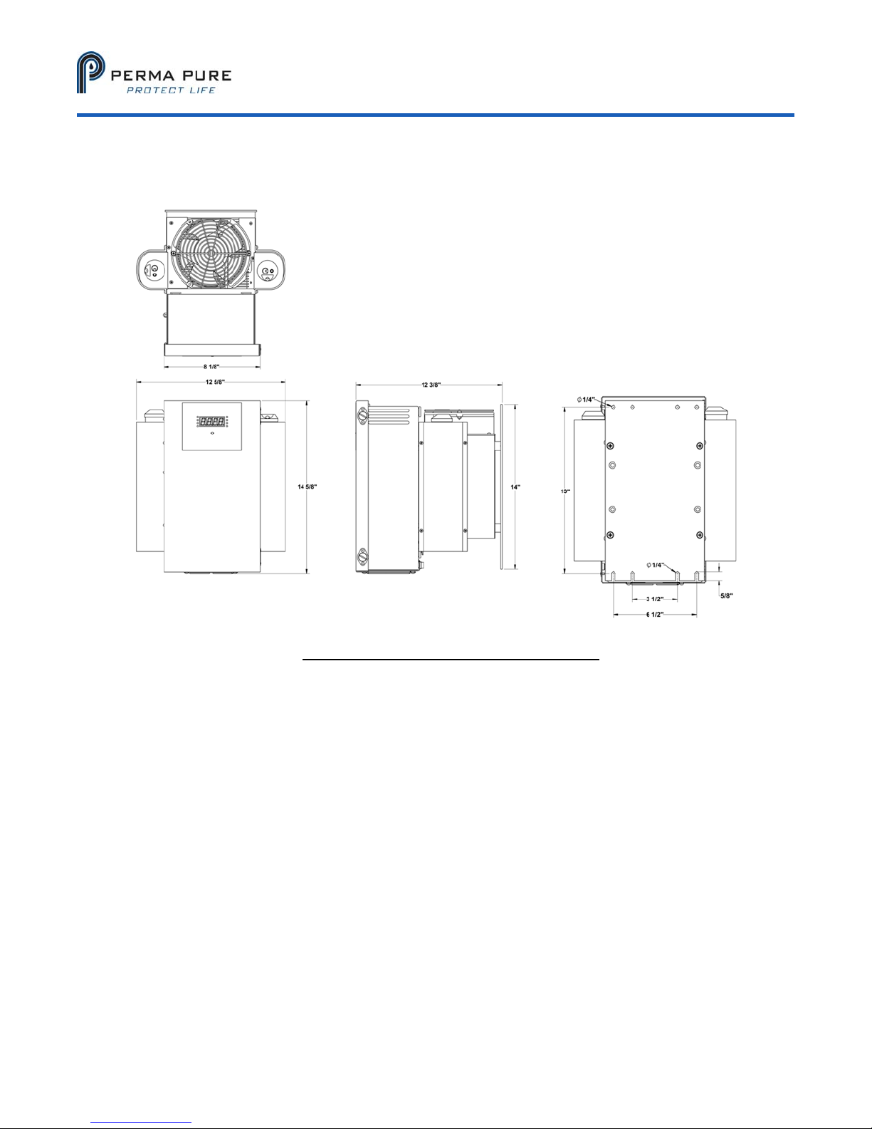
APPENDIX A: COOLER DRAWINGS
Model 5210D User’s Manual
Doc. SE-MAN-050 REV 00
Figure A1: Model 5210D Dimensional Drawing
Page 20 of 25
©2017 Perma Pure LLC. All rights reserved. Specifications subject to change.
Page 21
Model 5210D User’s Manual
Doc. SE-MAN-050 REV 00
Figure A2: Impinger Diagram
©2017 Perma Pure LLC. All rights reserved. Specifications subject to change.
Page 21 of 25
Page 22
Model 5210D User’s Manual
Doc. SE-MAN-050 REV 00
APPENDIX B: SAMPLE CONDITIONING SYSTEM DRAWINGS
Figure B1: Flow Schematic
©2017 Perma Pure LLC. All rights reserved. Specifications subject to change.
Page 22 of 25
Page 23
Model 5210D User’s Manual
Doc. SE-MAN-050 REV 00
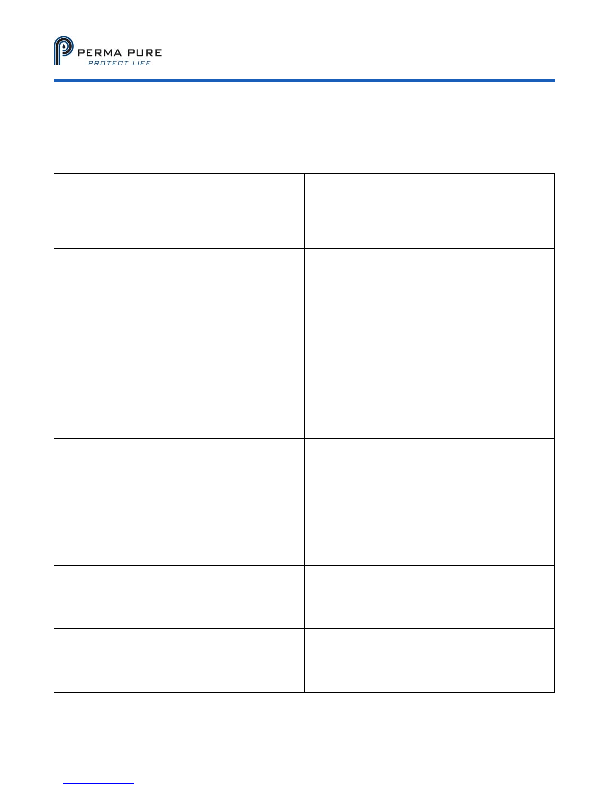
APPENDIX C: CONVERSION TABLES
CHART OF VOLUME PERCENT WATER CONCENTRATIONS AT SATURATION FOR VARIOUS
TEMPERATURES AT STANDARD PRESSURE (ATMOSPHERIC PRESSURE)
DEGREES C DEGREES F VOLUME % DEGREES C DEGREES F VOLUME %
+100
+ 90
+ 80
+ 75
+ 70
+ 65
+ 60
+ 55
+ 50
+ 45
+ 40
+ 35
+ 30
+ 29
+ 28
+ 27
+ 26
+ 25
+ 24
+ 23
+ 22
+ 21
+ 20
+ 19
+ 18
+ 17
+ 16
+ 15
+ 14
+ 13
+ 12
+ 11
+ 10
+ 9
+ 8
+ 7
+ 6
+ 5
+ 4
+ 3
+212
+194
+176
+167
+158
+149
+140
+131
+122
+113
+104
+ 95
+ 86
+ 84
+ 82
+ 81
+ 79
+ 77
+ 75
+ 73
+ 72
+ 70
+ 68
+ 66
+ 64
+ 63
+ 61
+ 59
+57
+ 55
+ 54
+ 52
+ 50
+ 48
+ 46
+ 45
+ 43
+ 41
+ 39
+ 37
100.00
69.20
46.70
38.70
30.70
25.20
19.70
15.50
12.20
9.45
7.25
5.55
4.19
3.95
3.73
3.62
3.32
3.13
2.94
2.77
2.61
2.46
3.31
2.17
2.04
1.91
1.79
1.68
1.58
1.48
1.38
1.29
1.21
1.13
1.03
0.988
0.922
0.861
0.803
0.751
+ 2
+ 1
0
-1
-2
-3
-4
-5
-6
-7
-8
-9
-10
-11
-12
-13
-14
-15
-16
-17
-18
-19
-20
-22
-24
-26
-28
-30
-32
-34
-36
-38
-40
-42
-44
-46
-48
-50
-52
-54
+ 36
+ 34
+ 32
+ 30
+ 28
+ 27
+ 25
+ 23
+ 21
+ 19
+ 18
+ 16
+ 14
+ 12
+ 10
+ 9
+ 7
+ 5
+ 3
+ 1
0
-2
-4
-8
-11
-15
-18
-22
-26
-30
-34
-37
-40
-44
-47
-51
-54
-58
-62
-65
0.696
0.649
0.602
0.555
0.510
0.469
0.431
0.396
0.363
0.333
0.305
0.281
0.256
0.234
0.214
0.196
0.179
0.163
0.148
0.135
0.123
0.112
0.102
0.084
0.069
0.057
0.046
0.038
0.031
0.025
0.019
0.016
0.013
0.011
0.008
0.006
0.005
0.004
0.003
0.002
©2017 Perma Pure LLC. All rights reserved. Specifications subject to change.
Page 23 of 25
Page 24
Model 5210D User’s Manual
Doc. SE-MAN-050 REV 00
DEW POINT
°F
-110 -166 .0000010 .00132 .0000053 0.00082
-108 -162 .0000018 .00237 .0000096 .0015
-106 -159 .0000028 .00368 .000015 .0023
-104 -155 .0000043 .00566 .000023 .0035
-102 -152 .0000065 .00855 .000035 .0053
-100 -148 .0000099 .0130 .000053 .0081
-98 -144 .000015 .0197 .000080 .012
-96 -141 .000022 .0289 .00012 .018
-94 -137 .000033 .0434 .00018 .027
-92 -134 .000048 .0623 .00026 .039
-90 -130 .00007 .0921 .00037 .057
-88 -126 .00010 .132 .00054 .082
-86 -123 .00014 .184 .00075 .11
-84 -119 .00020 .263 .00107 .16
-82 -116 .00029 .382 .00155 .24
-80 -112 .00040 .562 .00214 .33
-78 -108 .00056 .737 .00300 .46
-76 -105 .00077 1.01 .00410 .83
-74 -101 .00105 1.38 .00559 .86
-72 -98 .00143 1.88 .00762 1.17
-70 -94 .00194 2.55 .0104 1.58
-68 -90 .00261 3.43 .0140 2.13
-66 -87 .00349 4.59 .0187 2.84
-64 -83 .00464 6.11 .0248 3.79
-62 -80 .00614 8.08 .0328 5.01
-60 -76 .00808 10.6 .043 6.59
-58 -72 .0106 13.9 .0565 8.63
-56 -69 .0138 18.2 .0735 11.3
-54 -65 .0178 23.4 .0948 14.5
-52 -62 .0230 30.3 .123 18.8
-50 -58 .0295 38.8 .157 24.1
-48 -54 .0378 49.7 .202 30.9
-46 -51 .0481 63.3 .257 39.3
-44 -47 .0609 80.0 .325 49.7
-42 -44 .0768 101 .410 62.7
-40 -40 .0966 127 .516 78.9
-38 -36 .1209 159 .644 98.6
-36 -33 .1507 198 .804 122.9
-34 -29 .1873 246 1.00 152
-32 -26 .2318 305 1.24 189
-30 -22 .2859 376 1.52 234
-28 -18 .351 462 1.88 287
-26 -15 .430 566 2.30 351
-24 -11 .526 692 2.81 430
-22 -8 .640 842 3.41 523
-20 -4 .776 1020 4.13 633
-18 0 .939 1240 5.00 770
-16 +3 1.132 1490 6.03 925
-14 +7 1.361 1790 7.25 1110
-12 +10 1.632 2150 8.69 1335
-10 +14 1.950 2570 10.4 1596
-8 +18 2.326 3060 12.4 1900
-6 +21 2.765 3640 14.7 2260
-4 +25 3.280 4230 17.5 2680
-2 +28 3.880 5100 20.7 3170
0 +32 4.579 6020 24.4 3640
+2 +36 5.294 6970 28.2 4330
+4 +39 6.101 8030 32.5 4990
+6 +43 7.013 9230 37.4 4730
+8 +46 8.045 10590 42.9 6580
+10 +50 9.029 12120 49.1 7530
+12 +54 10.52 13840 56.1 8600
+14 +57 11.99 15780 63.9 9800
+16 +61 13.63 17930 72.6 11140
+18 +64 15.48 20370 82.5 12650
+20 +68 17.54 23080 93.5 14330
+22 +71 19.827 26088 16699
+24 +75 33.377 29443 18847
+26 +79 25.209 33169 21232
DEW POINT
°C
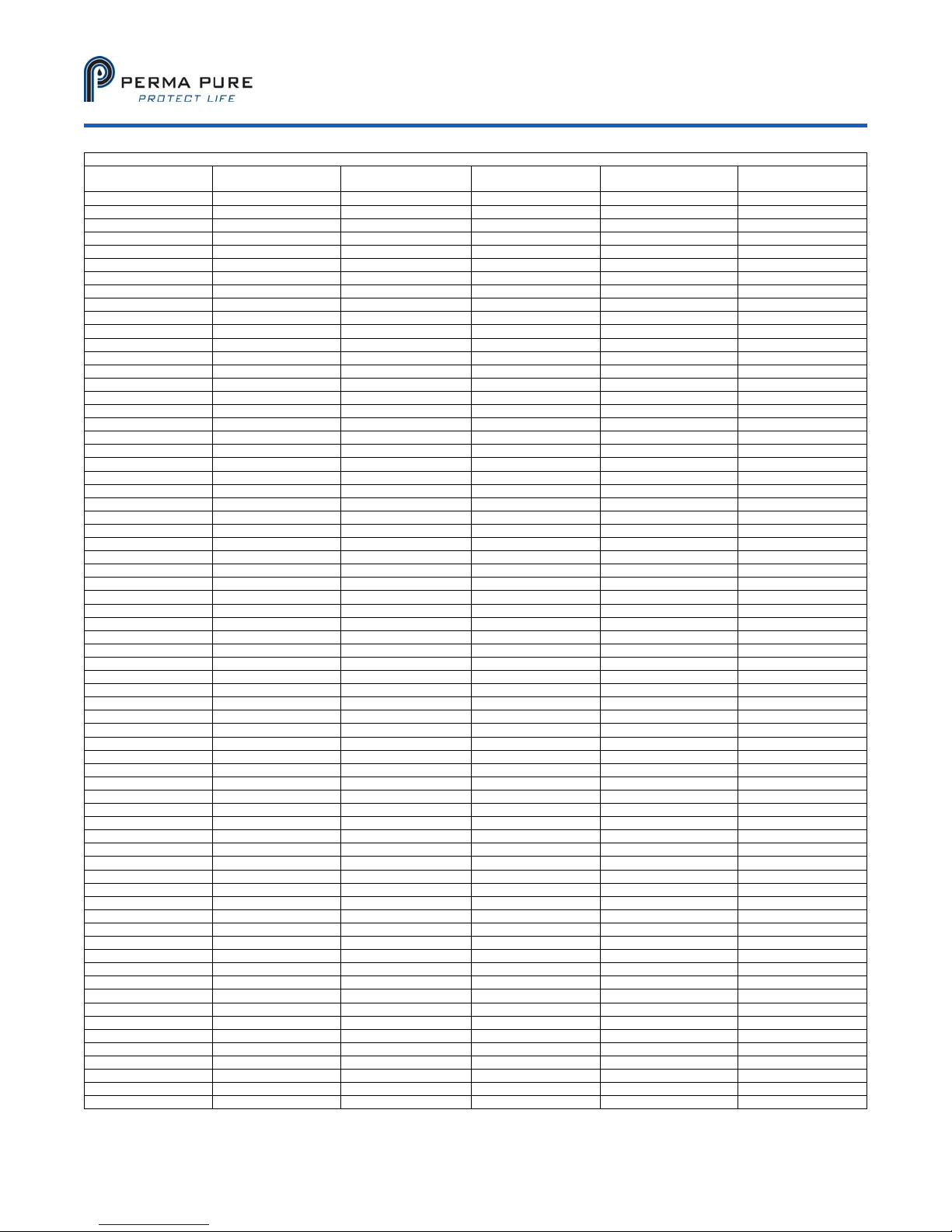
MOISTURE CONVERSION TABLE
VAPOR PRESSURE
Mm Hg
ppm by VOLUME
RELATIVEHUMIDITY
@70°F
ppm by WEIGHT
Page 24 of 25
©2017 Perma Pure LLC. All rights reserved. Specifications subject to change.
in air
Page 25

Model 5210D User’s Manual
Doc. SE-MAN-050 REV 00
APPENDIX D: WARRANTY AND DISCLAIMER
Perma Pure LLC
Perma Pure (Seller) warrants that product supplied hereunder shall, at the time of delivery to Buyer, conform to
the published specifications of Seller and be free from defects in material and workmanship under normal use and
service. Seller’s sole obligation and liability under this warranty is limited to the repair or replacement at its factory,
at Seller’s option, of any such product which proves defective within one year after the date of original shipment
from seller’s factory (or for a normal usable lifetime if the product is a disposable or expendable item) and is found
to be defective in material or workmanship by Seller’s inspection.
Buyer agrees that (1) any technical advice, information, suggestions, or recommendations given to Buyer by
Seller or any representative of Seller with respect to the product or the suitability or desirability of the product for
an particular use or application are based solely on the general knowledge of Seller, are intended for information
guidance only, and do not constitute any representation or warranty by Seller that the product shall in fact be
suitable or desirable for any particular use or application; (2) Buyer takes sole responsibility for the use and
applications to which the product is put and Buyer shall conduct all testing and analysis necessary to validate the
use and application to which Buyer puts the product for which Buyer may recommend the use or application of the
product by others; and (3) the characteristics, specifications, and/or properties of the product may be affected by
the processing, treatment, handling, and/or manufacturing of the product by Buyer or others and Seller takes no
responsibility for he nature or consequence of such operations or as to the suitability of the product for the
purposes intended to be used by Buyer or others after being subjected to such operations.
SELLER MAKES NO OTHER WARRANTY, EXPRESS OR IMPLIED, OF THE PRODUCT SUPPLIED
HEREUNDER, INCLUDING, WITHOUT LIMITATION, IMPLIED WARRANTIES OF MERCHANTABILITY AND
FITNESS FOR PARTICULAR PURPOSE, AND ALL SUCH WARRANTIES ARE HEREBY EXPRESSLY
EXCLUDED. SELLER SHALL HAVE NO LIABILITY FOR LOSS OF PROFITS, OR SPECIAL, INCIDENTAL, OR
CONSEQUENTIAL DAMAGES UNDER ANY CIRCUMSTANCES OR LEGAL THEORY, WHETHER BASED ON
NEGLIGENCE, BREACH OF WARRANTY, STRICT LIABILITY, TORT, CONTRACT, OR OTHERWISE. SELLER
SHALL IN NO EVENT BE LIABLE IN RESPECT OF THIS ORDER AND OR PRODUCT DELIVERED ON
ACCOUNT OF THIS ORDER FOR ANY AMOUNT GREATER THAN THAT PAID TO SELLER ON ACCOUNT
OF THIS ORDER.
©2017 Perma Pure LLC. All rights reserved. Specifications subject to change.
Page 25 of 25
 Loading...