

Page 1
INSTRUCTION MANUAL
Perma Pure LLC Integrator Series
SERIES – SAMPLE GAS DRYING SYSTEM
V7/11 1
Page 2

Table of Contents 2
Page 3

Table of Contents
A: Specifications .............................................................................................................. 5
Physical Description ......................................................................................................... 5
Operating Specifications ................................................................................................... 5
B: Limited Warranty ......................................................................................................... 7
C: Principle of Operation ................................................................................................. 9
D: Installation ................................................................................................................ 11
Mounting ..........................................................................................................................11
Tubing Connections .........................................................................................................12
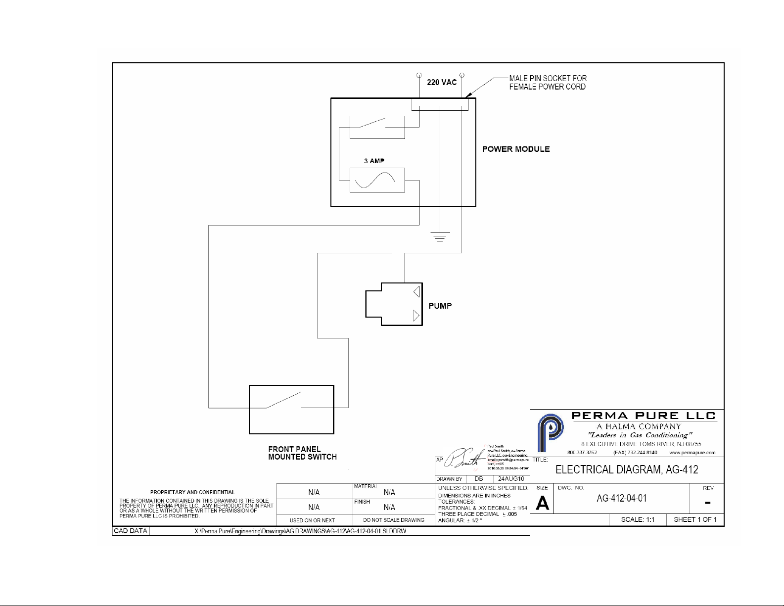
Electrical Connections .....................................................................................................12
E: Start-up Procedure .................................................................................................... 13
F: Drawings ................................................................................................................... 14
AG-412-05-01: Plumbing Diagram for MDSS Series ........................................................16
AG-412-04-01: Electrical drawing for MDSS Series .........................................................18
AG-412-03-01: Wall mounted MD Split Sample conditioning system ...............................20
AG-193U-03-01: Rack mounted MD Split Sample conditioning system ...........................22
H: Test & Adjustment Procedures ................................................................................. 23
Table of Contents 3
Page 4

Section A: Specifications 4
Page 5

A: SPECIFICATIONS
Sample Gas Flow Range
0.5-1.5 Lpm @ 380mm Hg (15” Hg)
Sample gas humidity inlet
Maximum 95% RH at room temperature, non-condensing
Dimensions
305mm x 305mm x 102mm (12” x 12” x 4”)
Weight
3.3 Kg. (7.3 lbs)
Inlet Sample Temperature
1-45°C
Maximum Inlet Pressure
1 Bar (15 psig)
Ambient Temperature Range
1° - 45°C (33° - 113°F)
Inlet Dew Point at rated flow
20°C
Outlet Sample Gas Dew Point
(based on 20C saturated inlet humidity)
-1°C @ 0.5 Lpm sample flow rate
4°C @1.0 Lpm sample flow rate
10°C @ 1.5 Lpm sample flow rate
Inlet Tubing Connection
¼” tube (compression)
Outlet Tubing Connection
¼” tube (compression)
Purge (Pump) outlet Connection
¼” tube (compression)
Power Requirement
230 VAC, 50 Hz, 3A
Ambient operating humidity range
0-95% RH, non-condensing
Physical Description
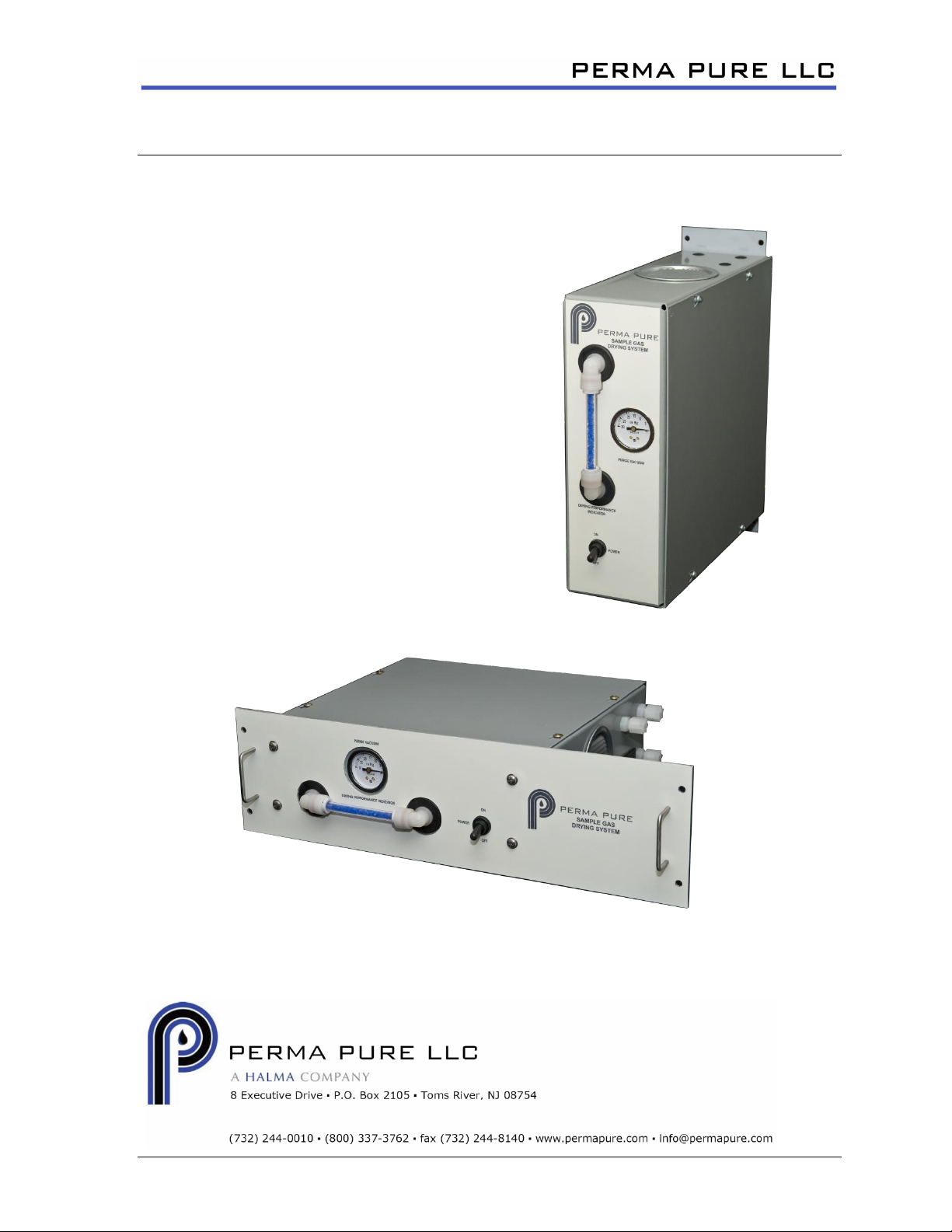
AG-412 Model – Vertically surface mounted system in aluminum case with removable cover.
AG-193U Model – 19” rack mounted system in aluminum case with removable cover. 3U
panel height.
Operating Specifications
Section A: Specifications 5
Page 6

Section B: Warranty 6
Page 7

B: LIMITED WARRANTY
Perma Pure LLC
WARRANTY and DISCLAIMERS
Perma Pure (Seller) warrants that product supplied hereunder shall, at the time of delivery to Buyer,
conform to the published specifications of Seller and be free from defects in material and
workmanship under normal use and service. Seller’s sole obligation and liability under this warranty is
limited to the repair or replacement at its factory, at Seller’s option, of any such product which proves
defective within one year after the date of original shipment from seller’s factory (or for a normal
usable lifetime if the product is a disposable or expendable item) and is found to be defective in
material or workmanship by Seller’s inspection.
Buyer agrees that (1) any technical advice, information, suggestions, or recommendations given to
Buyer by Seller or any representative of Seller with respect to the product or the suitability or
desirability of the product for an particular use or application are based solely on the general
knowledge of Seller, are intended for information guidance only, and do not constitute any
representation or warranty by Seller that the product shall in fact be suitable or desirable for any
particular use or application; (2) Buyer takes sole responsibility for the use and applications to which
the product is put and Buyer shall conduct all testing and analysis necessary to validate the use and
application to which Buyer puts the product for which Buyer may recommend the use or application of
the product by others; and (3) the characteristics, specifications, and/or properties of the product may
be affected by the processing, treatment, handling, and/or manufacturing of the product by Buyer or
others and Seller takes no responsibility for he nature or consequence of such operations or as to the
suitability of the product for the purposes intended to be used by Buyer or others after being
subjected to such operations.
SELLER MAKES NO OTHER WARRANTY, EXPRESS OR IMPLIED, OF THE PRODUCT
SUPPLIED HEREUNDER, INCLUDING, WITHOUT LIMITATION, IMPLIED WARRANTIES OF
MERCHANTABILITY AND FITNESS FOR PARTICULAR PURPOSE, AND ALL SUCH
WARRANTIES ARE HEREBY EXPRESSLY EXCLUDED. SELLER SHALL HAVE NO LIABILITY
FOR LOSS OF PROFITS, OR SPECIAL, INCIDENTAL, OR CONSEQUENTIAL DAMAGES UNDER
ANY CIRCUMSTANCES OR LEGAL THEORY, WHETHER BASED ON NEGLIGENCE, BREACH
OF WARRANTY, STRICT LIABILITY, TORT, CONTRACT, OR OTHERWISE. SELLER SHALL IN
NO EVENT BE LIABLE IN RESPECT OF THIS ORDER AND OR PRODUCT DELIVERED ON
ACCOUNT OF THIS ORDER FOR ANY AMOUNT GREATER THAN THAT PAID TO SELLER ON
ACCOUNT OF THIS ORDER
Section B: Warranty 7
Page 8

Section C: Principle of Operation 8
Page 9

C: PRINCIPLE OF OPERATION
The AG-412/193U system is a passive system in the sense that it will not move the sample
gas from point A to point B. It will only dry sample gas that is pushed or pulled through it by
an external pump or pressure/vacuum source. The pump in the system is present only to
provide a vacuum source on the purged side of the membrane dryer.
As sample gas is drawn or pushed through the system by the external pump or
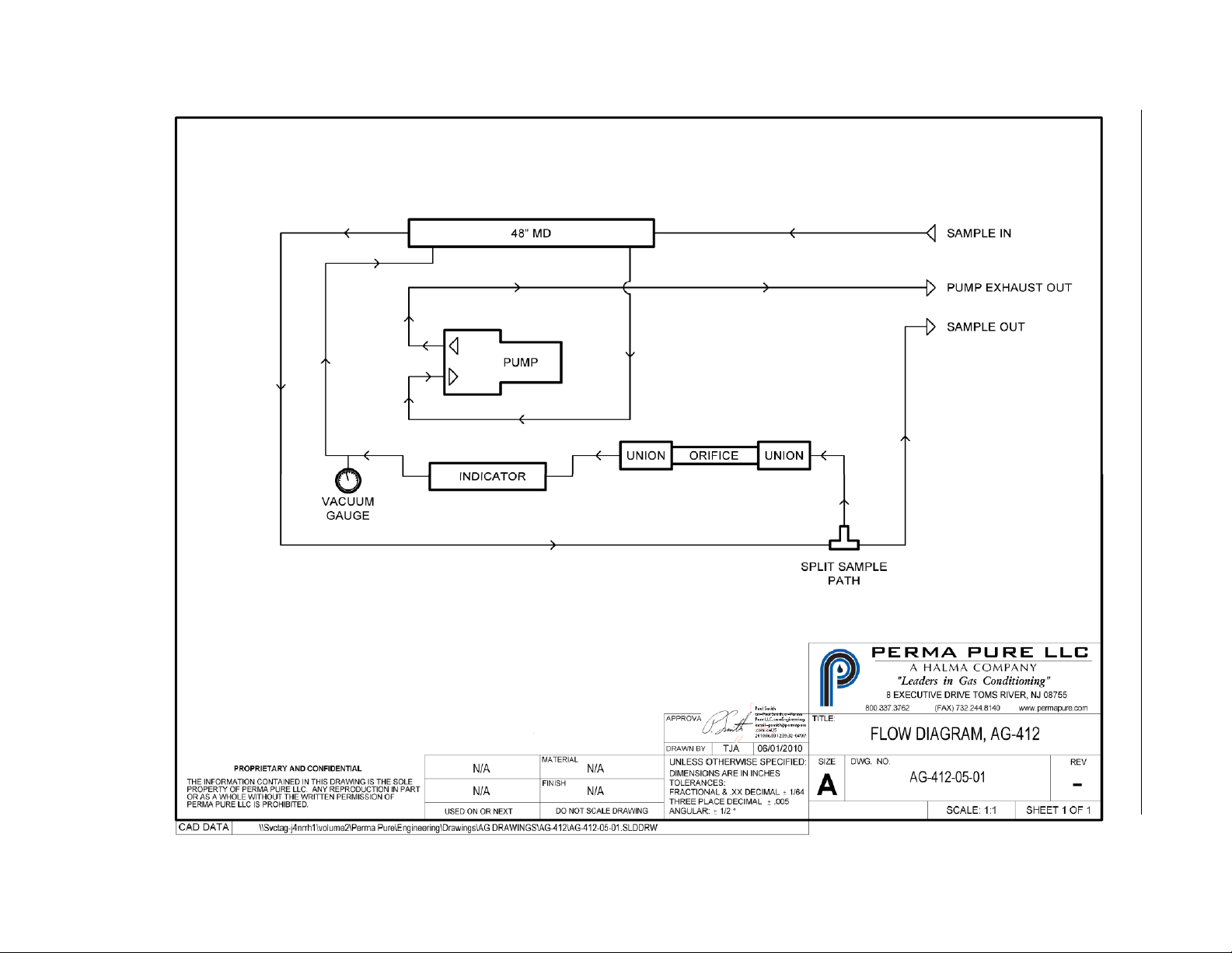
pressure/vacuum source, it is dried to a low moisture condition. A precision orifice serves to
meter a portion of the dried sample gas into the purged portion of the dryer. After passing
through this orifice, the pressure of the gas drops to about 15”hg. This change in total
pressure of the sample gas also lowers the partial pressure of the water vapor contained in
the gas effectively making it dry enough to be used as purge gas for the membrane dryer.
This purge gas sweeps away the moisture that is being removed from the sample gas flow
by the membrane tube in the dryer.
A silica gel filled tube on the front panel is used in the purge stream to indicate proper
operation. Initially, the silica gel indicator may be blue or pink depending upon the storage
conditions of the system. Once the system is put into operation and within a short period of
time, the silica gel will turn to a mostly light purple color, indicating the sample gas is dry and
ready for analysis. The silica gel material is blue when very dry and pink when not dry.
A vacuum gauge on the front panel shows the level of vacuum as an indication that the
purge pump is functioning.
Section C: Principle of Operation
9
Page 10

Section C: Principle of Operation
10
Page 11
D: INSTALLATION
Mounting
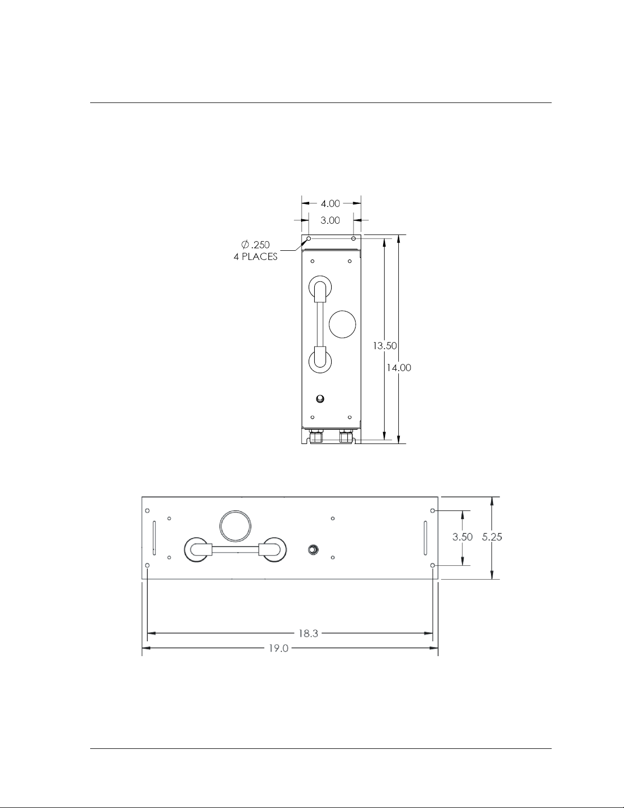
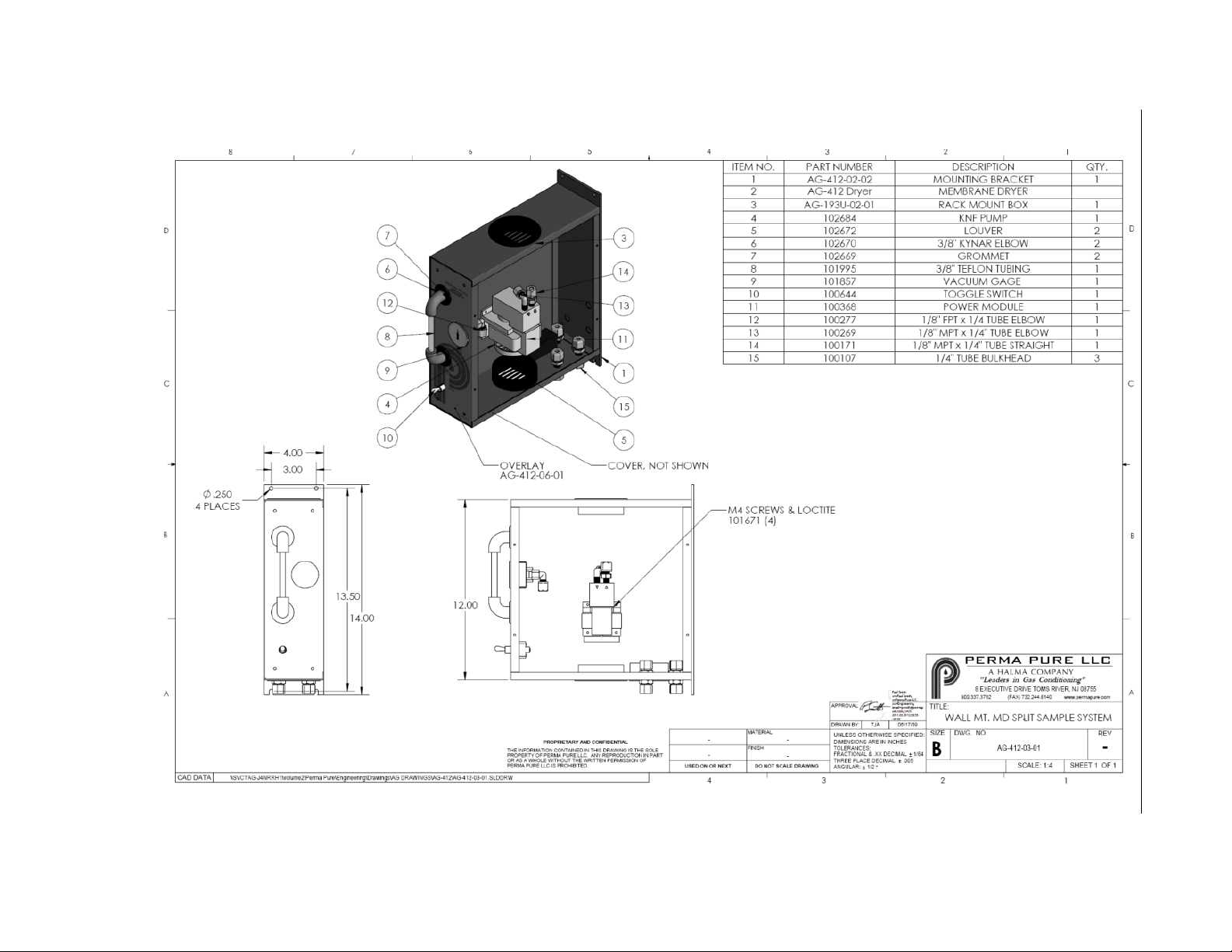
Mount AG-412 on a vertical surface using fasteners appropriate for the surface on which it is
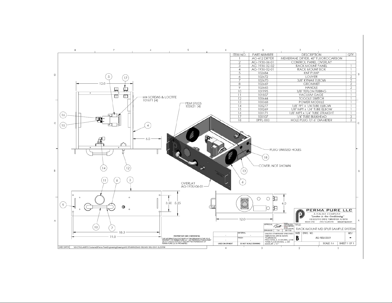
to be mounted or install AG-193U in a standard 19” rack cabinet.
Figure 1 - AG-412 Mounting
Figure 2 - AG-193U Mounting
Section D: Installation
11
Page 12
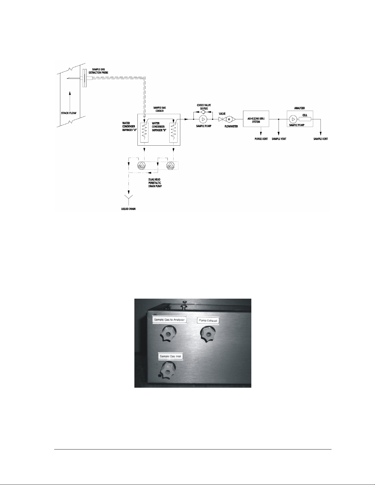
The suggested typical System connection method is shown below.
Figure 3 - Typical Connection Diagram
Tubing Connections
Connect the sample inlet port to sample line from the sample pump.
Connect the sample gas outlet to the analyzer via a tee fitting that allows excess
sample flow to be vented.
If required, due to sample gas composition, connect pump (purge) exhaust port to a
tube that allows the system to vent in a suitable location. This is very important if the
sample gas is toxic or corrosive.
Figure 4 - Tubing Connections
Electrical Connections
Connect the system to an appropriate power source while following all local and
regional electrical codes and guidelines.
Section D: Installation
12
Page 13

E: START-UP PROCEDURE
Be sure the analyzer is off and that no sample gas is being drawn through the analyzer.
After confirming that the system has been properly installed, turn on the main power switch
at the power inlet module. Turn the system on with the front panel power switch. The pump
will start and the vacuum level will remain higher than 15”Hg when the system is operating
properly. The flow meter between the pump and the AG-412/193U system should be set to
a flow rate that is just slightly higher than the flow that the analyzer pump is set to deliver an
never more that about 1.5lpm. Sample gas flow greater than 1.5 lpm will greatly reduce the
drying effectiveness of the system. Allow the system to run for about 1/2hr before turning on
the analyzer pump for the first time. At this point the vacuum level should be greater than
15”Hg and the indicator on the front panel will have at least a few areas of blue silica gel
crystals. The analyzer pump may now be started.
Section E Start-Up Procedure
13
Page 14

F: DRAWINGS
Section F: Drawings
14
Page 15

Section F: Drawings
15
Page 16
Section F: Drawings
AG-412-05-01: Plumbing Diagram for MDSS Series
16
Page 17

Section F: Drawings
17
Page 18
Section F: Drawings
AG-412-04-01: Electrical drawing for MDSS Series
18
Page 19

Section F: Drawings
19
Page 20
Section F: Drawings
AG-412-03-01: Wall mounted MD Split Sample conditioning system
20
Page 21

Section F: Drawings
21
Page 22
Section F: Drawings
AG-193U-03-01: Rack mounted MD Split Sample conditioning system
22
Page 23

H: TEST & ADJUSTMENT PROCEDURES
NOTE: All test and adjustment procedures have been performed at the factory.
For further service assistance, contact:
Perma Pure LLC
8 Executive Drive
Toms River, NJ 08755
Tel: 800-337-3762 (toll free U.S.)
Tel: 732-244-0010
Fax: 732-244-8140
Email: [email protected]
or your local representative
Section H: Test and Adjustment Procedures 23
 Loading...