


PAL-AT Installation Manual
Notice
The information contained in this manual, including but not limited to any product specifications, is subject to
change without notice.
PERMALERT (PERMALERT), A DIVISION OF PERMA-PIPE, INC., PROVIDES NO WARRANTY WITH REGARD
TO THIS MANUAL OR ANY OTHER INFORMATION CONTAINED HEREIN AND HEREBY EXPRESSLY
DISCLAIMS ANY WARRANTIES, INCLUDING IMPLIED WARRANTIES, OF MERCHANTABILITY OR FITNESS
FOR ANY PARTICULAR PURPOSE WITH REGARD TO ANY OF THE FOREGOING. PERMALERT ASSUMES
NO LIABILITY FOR ANY DAMAGES INCURRED DIRECTLY OR INDIRECTLY FROM ANY TECHNICAL OR
TYPOGRAPHICAL ERRORS OR OMISSIONS CONTAINED HEREIN OR FOR DISCREPANCIES BETWEEN THE
PRODUCT AND THE MANUAL. IN NO EVENT SHALL PERMALERT BE LIABLE FOR ANY INCIDENTAL,
CONSEQUENTIAL, SPECIAL, OR EXEMPLARY DAMAGES, WHETHER BASED ON TORT, CONTACT OR
OTHERWISE, ARISING OUT OF OR IN CONNECTION WITH THIS MANUAL OR ANY OTHER INFORMATION
CONTAINED HEREIN OR THE USE THEREOF.
Caution --This manual may not be up-to-date.
Please check the PermAlert website, www.permalert.com, for the latest revision of this manual.
The manual is typically revised at least once a year. The revision date is on the back cover.
Contact techsupport@permalert.com for technical assistance with the PAL-AT system.
2

Table of Contents
Safety Information ............................................................................................ 7
1 Introduction ............................................................................................... 8
1.1 General Description .......................................................................................................... 8
1.2 Applications ...................................................................................................................... 8
1.3 Receiving and Handling Precautions ................................................................................ 8
1.4 Materials and Equipment Normally Supplied by PermAlert .............................................. 8
1.5 Materials and Equipment Normally Supplied by Installing Contractor .............................. 9
2 PAL-AT Alarm/Locator Panel ................................................................. 10
2.1 Alarm/Locator Panel Installation ..................................................................................... 10
2.2 Terminals........................................................................................................................ 11
2.3 Power Connection .......................................................................................................... 11
2.4 Audible Alarm Wiring ...................................................................................................... 11
2.5 Control Relays ................................................................................................................ 11
2.6 Communications ............................................................................................................. 14
2.6.1 Port 1 - RS-485/RS-232 ....................................................................................... 14
2.6.2 Port 2 - RS-232 .................................................................................................... 14
2.6.3 Ethernet ............................................................................................................... 14
2.6.4 Ethernet Auto-Negotiate Selection ...................................................................... 15
2.7 Replaceable Parts ............................................................................................... 15
2.7.1 Battery ................................................................................................................. 15
2.7.2 24 VDC Fuse ....................................................................................................... 15
2.8 Contrast Adjustment ....................................................................................................... 15
2.9 Impedance Jumper Setting............................................................................................. 16
2.10 UL ................................................................................................................................... 16
2.11 FCC and CE Compliance Requirements ........................................................................ 16
3 Zener Barrier Panel ................................................................................. 17
3.1 Introduction..................................................................................................................... 17
3.2 Panel Installation ............................................................................................................ 17
3.3 Panel Wiring ................................................................................................................... 19
3.4 Zener Barrier Assembly (ZBA) Installation ..................................................................... 19
3.5 Fuse Protection .............................................................................................................. 19
3.6 Allowable Cables and Probes......................................................................................... 19
4 Jumper Cable and Junction Box Installation ........................................ 20
4.1 Jumper Cable ................................................................................................................. 20

PAL-AT Installation Manual
4.2 Calibration Points ........................................................................................................... 21
4.3 Junction Boxes ............................................................................................................... 21
5 Cable Installation in Secondary Contained Piping ............................... 22
5.1 General .......................................................................................................................... 22
5.2 Pull Points ...................................................................................................................... 23
5.3 Cable Splices ................................................................................................................. 25
5.3.1 Factory Installed Fiber Pull Rope to Continuous Pull Wire Rope Splice .............. 25
5.3.2 Wire Rope to Wire Rope Splice ........................................................................... 26
5.3.3 Wire Rope to Wire Rope Splice (alternate).......................................................... 27
5.3.4 Wire Rope to Leak Detection Cables .................................................................. 28
5.4 Installation of the Continuous Pull Rope ........................................................................ 30
5.5 Installing Sensor and Jumper Cables ............................................................................. 32
5.6 Air Testing ...................................................................................................................... 35
6 Installation of Direct Buried Sensor Cable ............................................ 36
6.1 General .......................................................................................................................... 36
6.2 Installing the Sensor Cable ............................................................................................ 37
6.3 Above Ground Storage Tanks ........................................................................................ 40
7 Cable Installation for Raised Floor and Ceilings .................................. 42
7.1 General .......................................................................................................................... 42
7.2 Install the Sensor Cable ................................................................................................. 42
7.3 Locator Chart ................................................................................................................. 43
7.4 Calibration and end of run Access Points ...................................................................... 43
8 Cable Connectors ................................................................................... 44
8.1 General .......................................................................................................................... 44
8.2 Cable Connector Installation .......................................................................................... 44
8.2.1 CAGOLD and CATFH Connectors for Sensor Cables AGW-Gold, AGT-Gold,
TFH-Gold and TFH .............................................................................................. 44
8.2.2 CAJMP Connectors for Jumper Cables JMP-U/-UD ........................................... 47
8.2.3 CAJPP Connectors for Jumper Cables JPP and JMP ......................................... 49
8.2.4 CAGOLD Connector for ATP Cable .................................................................... 50
8.3 Shrink Tubing ................................................................................................................. 52
8.3.1 Cable Type TFH .................................................................................................. 52
8.3.2 Cable Types AGW-Gold, AGT-Gold and TFH-Gold ............................................ 53
8.3.3 Cable Types JMP-U/-UD, JPP and JMP ............................................................. 54
8.4 Cable and Connector Testing Procedures ..................................................................... 54
8.4.1 General................................................................................................................ 54
8.4.2 Continuity Test .................................................................................................... 54
4

PAL-AT Installation Manual
8.4.3 Alternative System Test ....................................................................................... 55
8.4.4 Insulation Test ..................................................................................................... 55
8.5 Cable Connections to Panels ......................................................................................... 55
8.5.1 General ................................................................................................................ 55
8.5.2 Ferrule Installation in PAL-AT Panel .................................................................... 55
8.5.3 Ferrule Installation in Zener Barrier Panel ........................................................... 57
8.5.4 ATP Cable Connection at PAL-AT ....................................................................... 59
9 Probes ..................................................................................................... 60
9.1 UL Requirements ........................................................................................................... 60
9.2 Probe Integrator Selection .............................................................................................. 60
9.3 Probe Installation ............................................................................................................ 60
9.4 PHLR Hydrocarbon Probe .............................................................................................. 62
9.4.1 Cleaning Sensor Elements Procedure ................................................................. 63
9.4.2 Testing the Probe ................................................................................................ 64
9.4.3 Troubleshooting ................................................................................................... 64
9.4.4 Calibrating the Probe ........................................................................................... 64
9.5 Typical Installations ........................................................................................................ 65
9.6 Probe Tests .................................................................................................................... 70
10 ATP Cable in Polyurethane Foam Insulation ........................................ 72
10.1 General .......................................................................................................................... 72
10.2 Pipe Installation Precautions .......................................................................................... 72
10.3 System Configuration ..................................................................................................... 72
10.4 Calibration Points ........................................................................................................... 72
10.5 ATP Cable and Connector Testing Procedures.............................................................. 72
10.5.1 Continuity Test ..................................................................................................... 73
10.5.2 Insulation Test ..................................................................................................... 73
10.5.3 Insulation Test with Wet Cloth ............................................................................. 74
10.6 Start of Run .................................................................................................................... 74
10.7 ATP Cable Splices ......................................................................................................... 75
10.8 ATP Cable at Tee Connections ...................................................................................... 77
10.9 End of Run Termination ................................................................................................. 78
10.10 Requirements for Field Joints with Wind-Down End Seals .................................. 79
Appendix A – Special Instructions ............................................................... 80
A.1 Supply Power ................................................................................................................. 80
A.2 Control Drawing .............................................................................................................. 80
A.3 Zener Barrier Panel (ZBP) .............................................................................................. 80
A.4 Probe Integrator ............................................................................................................. 80
A.5 Probe Integrator Static Precautions ................................................................................ 80
5

PAL-AT Installation Manual
A.6 ZBP Enclosure Fittings ................................................................................................... 81
WARRANTY .................................................................................................... 83
6
PAL-AT Installation Manual
Safety Information
Please Read This Installation Manual
Please take the time to read this installation manual carefully. It will help you set up and operate your system
properly. Failure to follow these instructions may impair the safety of the equipment. Please save this
installation manual for future reference.
For your safety
Caution: To reduce the risk of fire or electric shock, do not expose the PAL-AT to rain or moisture.
This symbol alerts the user to the presence of uninsulated, dangerous voltage within the system
enclosure that may be of sufficient magnitude to constitute a risk of electric shock.
This symbol alerts the user to the presence of important operating and maintenance instructions in
this manual.
Approvals and Certifications
CAUTION: TO REDUCE THE RISK OF ELECTRIC SHOCK,
TURN OFF POWER BEFORE OPENING ENCLOSURE DOOR.
REFER ALL SERVICING TO QUALIFIED PERSONNEL
Regulatory Compliance Statements
FCC Class A Notice
This device complies with part 15 of the FCC Rules. Operation is subject to the following two conditions.
1. This device may not cause harmful interference, and
2. This device must accept any interference received, including interference that may cause undesired operation
NOTE: This equipment has been tested and found to comply with the limits for a Class A digital device, pursuant to Part 15 of the FCC
Rules. These limits are designed to provide reasonable protection against harmful interference when the equipment is operated in a
commercial environment. This equipment generates, uses, and can radiate radio frequency energy and, if not installed and used in
accordance with this instruction manual, may cause harmful interference to radio communications.
Operation of this equipment in a residential area is likely to cause harmful interference in which case the user will be required to correct the
interference at his own expense.
Changes or modifications not expressly approved by the party responsible for compliance could void the user’s authority to operate the
equipment.
The party responsible for product compliance:
Perma-Pipe, Inc.
6410 W. Howard St.
Niles, IL 60714
7

1.1 General Description
This PAL-AT® Installation Manual is intended for use as a general installation guide for PAL-AT
alarm/locator panels, sensor cable, cable connectors, and probes. Users (installers) should independently
evaluate the suitability of this information and PermAlert's products for their application and specific
installation. If you receive a PermAlert product not described in this manual, contact PermAlert for the
appropriate instructions. PermAlert is a division of Perma-Pipe, Inc. Refer to the PermAlert website,
permalert.com, for the latest revision of manuals and product data sheets.
1.2 Applications
The PAL-AT system consists of an electronic microprocessor-based alarm/locator panel that monitors
sensor cables and/or probes. The sensor cable may be installed in many applications including:
secondary contained piping; directly in the ground adjacent to fuel pipes or tanks; computer room
subfloors; cleanroom subfloors, or any area where liquids need to be detected. There are several PALAT models available including:
AT30C: Monitors 1 cable up to 3,000 ft [900 m].
AT75C: Monitors 1 cable up to 7,500 ft [2300 m].
AT30K: Monitors 4 cables each up to 7,500 ft [2300 m].
Applications monitoring cables in hazardous locations must use a Zener Barrier Panel (see section 3).
PAL-AT Installation Manual
1 Introduction
1.3 Receiving and Handling Precautions
The following general precautions should be observed:
1. Do not use substitute materials or short cut recommended procedures. Understanding and
following this guide is essential to avoid installation problems.
2. Collect the needed quantities of all materials well in advance of scheduled work.
3. Check the packing list against received items. Report immediately any shortages or damaged
materials to the delivering carrier.
4. All cable must be tested immediately upon receipt following the cable test procedures contained
in this manual. Report immediately to PermAlert any cables that fail the tests. Failure to report
within ten workdays of receipt of goods shall waive the purchaser's right to file a warranty claim.
5. The recommended minimum bend radius for all sensor and jumper cables is 1.5” [38mm].
6. Care must be taken to store all PAL-AT components in a dry and protected area at all times.
Electronic alarm/locator panels and sensor cable should be wrapped and sealed with plastic.
7. System drawings, provided by the designer, should indicate the extent, general location, and
arrangement of leak detection equipment, cable, and probes. The contractor (installer) should
become familiar with all details of the installation before proceeding.
8. Electrical work should be performed by a qualified electrician.
1.4 Materials and Equipment Normally Supplied by PermAlert
Each system may include the following items as quoted:
1. Leak detection/location alarm panel
2. Leak sensor cable
3. Jumper cable
4. Cable connector assemblies
5. Adhesive backed cable mounts (CMA) furnished for attachment of sensor cable to flat surfaces
6. Probe assembly, including a PT10 Probe Integrator installed in a NEMA 4X [IP66] junction box
with 60' of jumper cable and one cable connector assembly
7. Watertight junction boxes conforming to NEMA 4X [IP66].
8

PAL-AT Installation Manual
Maximum No. of
Cable Connectors
in Enclosure
1
2
4
8. Watertight cord grips
9. Shrink tubing for cable connectors
10. Non-corrosive RTV adhesive/sealant for cable connectors
Enclosure Dimensions
[150 mm x 150 mm x 100 mm]
[200 mm x 150 mm x 100 mm]
[250 mm x 200 mm x 100 mm]
1.5 Materials and Equipment Normally Supplied by Installing Contractor
Each system may require the installing contractor to supply the following items:
1. Pull rope, 1/8" [3 mm] diameter, 7 strands, steel wire rope aircraft cable. For installation of cable in
fiberglass or other plastic piping systems, use plastic coated (non-vinyl) wire rope. Provide pull rope
in quantities equal to 120% of system length. (Included with Perma-Pipe piping systems)
2. Cable spool rack or stand
3. PVC electrical tape
4. Miscellaneous pipe nipples, unions, and fittings, as required to provide watertight jumper cable
connections to sensor cable.
5. 1" rigid or liquid-tight flexible electrical conduit, as required, for installation of jumper cable within
manholes, pits, and buildings. Use 1" conduit hub, OZ Gedney CH-100, or equal, connection to
junction boxes.
6. Electrical conduit, junction boxes, and wiring, as required.
7. Ohmmeter for testing jumper cables and sensor cables.
8. 1000-volt megger for testing ATP sensor cable.
9. Hole saw or knockout punch.
10. Construction adhesive mastic for attachment of cable mounts to unsealed concrete surfaces
11. Hot air gun for shrink tube application on cable connector assemblies
6" x 6" x 4"
8" x 6" x 4"
10" x 8" x 4"
9

2 PAL-AT Alarm/Locator Panel
2.1 Alarm/Locator Panel Installation
The PAL-AT panel is designed to be permanently mounted indoors in a dry area. The enclosure is rated
Type 12 [IP52]. It must not be located in direct sunlight to prevent excessive heat buildup. In all
installations, the ambient temperature surrounding the PAL-AT panel must be within the limits
below. The equipment is designed to be safe in the following range of environmental conditions:
a) Indoor use;
b) Altitude up to 6,560 ft [2000 m];
c) Temperature -4°F [-20°C] to 122°F [50°C];
d) Maximum relative humidity 95%;
e) Pollution degree 2.
Warning: Do not mount the PAL-AT panel in a hazardous location. The panel must be in an
ordinary location even though sensor cables may be located in hazardous locations. Refer to the
Zener Barrier Panel section of this manual.
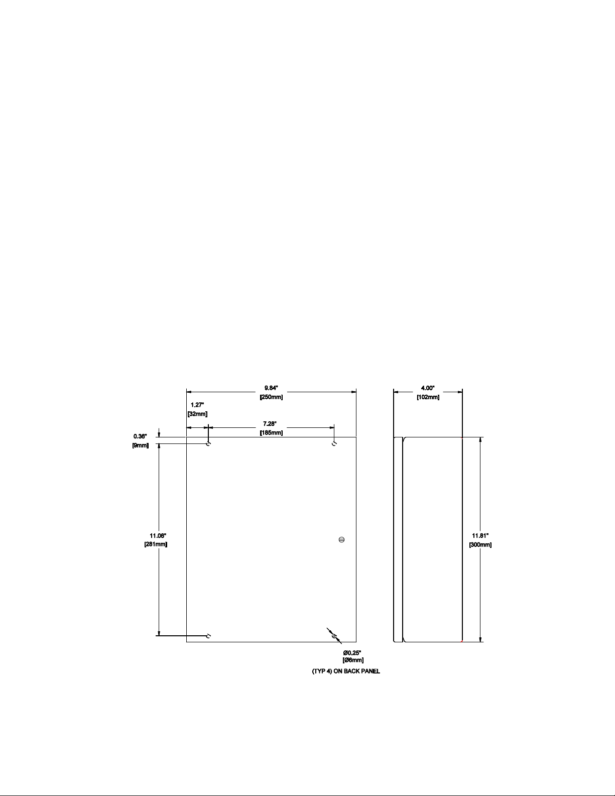
Mount the PAL-AT panel securely to a wall, using ¼” [M6] hardware in the 4 holes on the back of the panel
(see figure 2-1). If it is mounted to a typical ½” plasterboard wall, use ¼” x 1 ½” [M6 x 40mm] lag screws
to secure it to the studs (nominal 2” x 4” [50mm x 100mm]). The panel can also be mounted to steel
mounting channel struts using ¼” [M6] machine screws.
The PAL-AT panel is connected to the sensor cable using jumper cable (Type JMP-U, JMP-UD or JPP).
An exception to this requirement is ATP cable that uses 50’ [15 m] of ATP for jumper (see section 9). At
least 50' [15 m] of jumper cable (65' [20 m] if JPP) must be connected between the panel and the
connection to the sensor cable.
PAL-AT Installation Manual
The jumper cable must be run in a separate conduit from the power supply cable. All conduit fittings must
be appropriately rated and installed properly to maintain the rating of the enclosure. All electrical
connections must comply with local codes. Remove the system board from the white back panel (six
#6-32 screws) before drilling holes in the enclosure for conduit openings to prevent damage and
contamination from metal shavings.
Models AT30C, AT75C and AT30K
Mounting Dimensions
Figure 2-1
10

2.2 Terminals
The terminals on the PAL-AT system board use a quick-connect design that provides an easy, fast and
robust connection. A flat blade screwdriver, 1/8” [3.5 mm], is used to press down on the terminal lever
and open the terminal for easy wire insertion. Release the lever, and the wire is tightly clamped. The
acceptable wire size for connection to any terminal, including the mains, is 28 - 12 AWG [0.08-2.5
mm2]. The terminals can accommodate solid or stranded wires. If ferrules are used with stranded
wire, the maximum wire size is 14 AWG [1.5 mm2]. Refer to the detail located at the upper right side
of figures 2-2 and 2.3. Caution: The lever only travels 1/8” [3.5 mm] to open the terminal completely,
and only requires 5 - 8 lbs [2-4 kg] force. Do not exceed these limits or the terminal will be
damaged.
2.3 Power Connection
The PAL-AT must be permanently wired to instrument-quality power using appropriate certified conduit,
fittings, and wiring. Refer to figures 2-2 and 2-3 wiring diagrams for details. The PAL-AT contains a universal
power supply. The power requirement is 110-240 VAC, 50 / 60 Hz, 0.3 A / 50 VA.
A suitable external over-current protection device, such as a fuse or circuit breaker (15 A), and disconnect
device is recommended. The over-current protection and disconnect devices shall be installed on all
ungrounded conductors, i.e. the terminal marked hot (L) (and neutral (N) terminal if ungrounded for 240
VAC). The disconnect device shall be located near the equipment and marked with appropriate ON (l) OFF
(O) markings as specified by local codes. The ground conductor shall have green with a yellow stripe
insulation and be connected to the grounding connection on the upper right corner of the back panel as
shown. Installation should be performed by qualified personal in accordance with local codes and
procedures.
PAL-AT Installation Manual
The PAL-AT can also be powered by a 24 VDC, 1 A / 24 VA, over-current protected power source at terminal
T5. Fuse F1 on the PAL-AT system board protects the 24 VDC input. It is a 2A, 250 V, time-delay, 5 x 15
mm fuse.
Caution - Before accessing the PAL-AT panel, the panel must be disconnected from the power
source and isolated from any hazardous voltage present in the panel, e.g. relay wiring.
Three internal switches on the system board control the power source utilized by the panel. These switches
are intended for use by service personnel. Set the AC Power Switch (SW3) and the 24 VDC Power Switch
(SW1) in the down, or “OFF” position. Next, set the Input Power Select Switch (SW2) to either VAC or VDC
depending on the desired power source. The panel is controlled by SW3 for AC power or SW1 for DC
power.
2.4 Audible Alarm Wiring
An internal 90-dBA pulse horn is supplied. An optional chime alarm is available. The wiring for the horn
is a 2-wire cable connected to terminal strip T6. The red wire must be connected between the “+” terminal
on the horn and the “+” T6 terminal. The black wire must be connected between the “-” terminal on the
horn and the “-” T6 terminal. The terminal provides 24 VDC @ 10 mA.
2.5 Control Relays
PAL-AT has 3 to 6 SPDT output relays, depending on the model, rated for 250 VAC, 10 A. They are
labeled “Fault Alarm”, “Common Alarm” and “Cable x”, where x=1 to 4 for the appropriate cable number
(see figures 2-2 and 2-3). The relay contacts are labeled in their unpowered or “on-the-shelf” condition.
The fault relay energizes when the panel is powered and monitors for a power fault.
The common alarm relay switches state in response to any fault condition. The # key can be pressed to
reset the common alarm relay to its normal state and deactivate the internal audible alarm for up to 96
hours. The default reset time is 12 hours.
The cable relay(s) will activate when a fault is detected and will reset when the fault returns to normal or
the alarm queue is cleared. The default setting is to activate for all alarms, but it is firmware selectable to
activate in response to only leak and probe active alarms.
Control devices or auxiliary equipment should be connected to the cable relay(s) so they will not
be reactivated when the alarm is silenced. PAL-AT is shipped with the common alarm and cable
11

PAL-AT Installation Manual
relays configured to operate in a normally de-energized mode, so they energize when the panel is
in the alarm state (see the PAL-AT Operating Manual for changing relay configuration).
Figure 2-2
Wiring Diagram for PAL-AT Models AT30C & AT75C
12

PAL-AT Installation Manual
Figure 2-3
Wiring Diagram for PAL-AT Model AT30K
13

PAL-AT Installation Manual
2.6 Communications
PAL-AT is provided with several options for communication. The options include:
Port 1 – RS-485/RS-232
Port 2 – RS-232
Ethernet - RJ-45 connector
Refer to the PAL-AT Operating Manual for complete operating details and firmware configuration.
2.6.1 Port 1 - RS-485/RS-232
Port 1 can be configured for RS-485 or RS-232 (refer to figures 2-2 and 2-3). To configure it for RS-485,
jumper J2 should be placed in the top position. Then the two jumpers at J1 can be set to select either full
(top positions) or half-duplex (bottom positions).
Full duplex is available using two twisted-pairs connected to T1 terminals R+, R-, T+ and T-.
Half duplex, or 2-wire RS-485, requires a jumper wire connecting terminal R+ to T+ and a jumper from Rto T-. Each PAL-AT is a full load for the RS-485 network. A crimp ferrule is recommended to connect
each incoming RS-485 lead to the corresponding jumper wire to insure a solid connection of the two wires
in the T1 terminals.
All RS-485 cables in the network should be properly terminated as per EIA RS-485
recommendations. Typically the network is a daisy-chain configuration and two 120 ohm
termination resistors are installed, one at each end of the network. Shields of the network cables
should be connected together and grounded at only one point.
Port 1 can be configured for RS-232 by moving J2 to the bottom position. Then a 3-conductor cable
should be connected to T1 terminals GND, R1 (receive) and T1 (transmit). The baud rate is configured
via the PAL-AT firmware.
2.6.2 Port 2 - RS-232
RS-232 communications through port 2 requires a 3-conductor cable connected to T1 terminals GND, R2
(receive) and T2 (transmit). The baud rate is configured via the PAL-AT firmware.
2.6.3 Ethernet
An Ethernet RJ-45 jack provides a TCP connection to the PAL-AT. There are three ports available to
handle different protocols: port 1024 for ASCII data (PALCOM), port 502 for Modbus TCP, and port 1050
for Modbus RTU over TCP.
An optional BACnet gateway is also available. Refer to Modbus to BACnet Converter Instructions (DOCID:
PPPA-PRC-CSV-006) for more information.
Refer to the PAL-AT Operating Manual for complete operating details and firmware configuration.
14

2.6.4 Ethernet Auto-Negotiate Selection
Fixed 100Mb full duplex
By default, the PAL-AT is shipped with the Ethernet port permanently set to 100Mb / Full duplex.
Optionally, the port can be set to auto negotiate speed and duplex when required. This is most often
required when hard setting the switch port isn’t possible to allow 100Mb / full duplex, or when connecting
to a network that otherwise requires auto negotiation (i.e. Gigabit networks).
Ethernet auto negotiation is set through the placement of a jumper on the Auxiliary Header “J4”. The
header is located to the lower left of the power supply. Refer to Figure 2.3 for the exact location.
PAL-AT Installation Manual
NOTE: System must be power cycled after changing the jumper position.
permanently set (Legacy)
No Jumper or jumper not in active
position (across right pins or on 1 pin).
Default as shipped.
Jumper active in position 1
2.7 Replaceable Parts
Caution - Before accessing the PAL-AT panel, the panel must be disconnected from the power
source and isolated from any hazardous voltage present in the panel, e.g. relay wiring.
Auto Negotiate
2.7.1 Battery
Battery BT1 on the PAL-AT system board maintains the clock settings when the panel is off. Jumper J5,
located above the battery, must be set “On” (left position) to enable the battery. The battery is a 3 V lithium
type.
Replace Battery With Energizer CR2025 Only. Use of Another Battery May Present A Risk of
Fire or Explosion.
Caution, Battery May Explode if Mistreated. Do Not Recharge, Disassemble or Dispose Of in
Fire.
It can be obtained locally or through PermAlert. It is replaceable by gently lifting the retaining clip to remove
the old battery and sliding in the new one. Be careful to install the battery correctly. The lettering on the
battery (+) should be facing out.
2.7.2 24 VDC Fuse
In addition to a user supplied external overcurrent protection device, fuse F1 on the PAL-AT system board
protects the 24 VDC input. It is a 2 A, 250 V, time-delay, 5 x 15 mm fuse. It can be obtained locally or
through PermAlert.
2.8 Contrast Adjustment
The contrast of the LCD can be adjusted by turning the contrast adjustment screw on the system board
(see figures 2-2 and 2-3). This may be necessary to get the best viewing angle, depending on the
15
mounting height of the PAL-AT panel.
2.9 Impedance Jumper Setting
Refer to figures 2-2 and 2-3 for positioning the impedance jumper. The 2-pin jumper is placed in position
A, B, C, or D according to the type of cable and whether a Zener Barrier Assembly (for hazardous
locations) is connected to the selected cable. The position should be:
Jumper Position Cable Type Zener Barrier Ass’y Installed
A ATP only No
B ATP only N/A
C All others No
D All others Yes
2.10 UL
PAL-AT is listed by Underwriters Laboratories, Inc. for installation in ordinary locations. The optional Zener
Barrier Panel must be installed if any leak detection circuits are located in hazardous locations.
CAUTION - The maximum operating voltage allowed in the PAL-AT panel is 250 VAC. In
addition, the voltage on any wires to the control relays must be limited to 250 VAC.
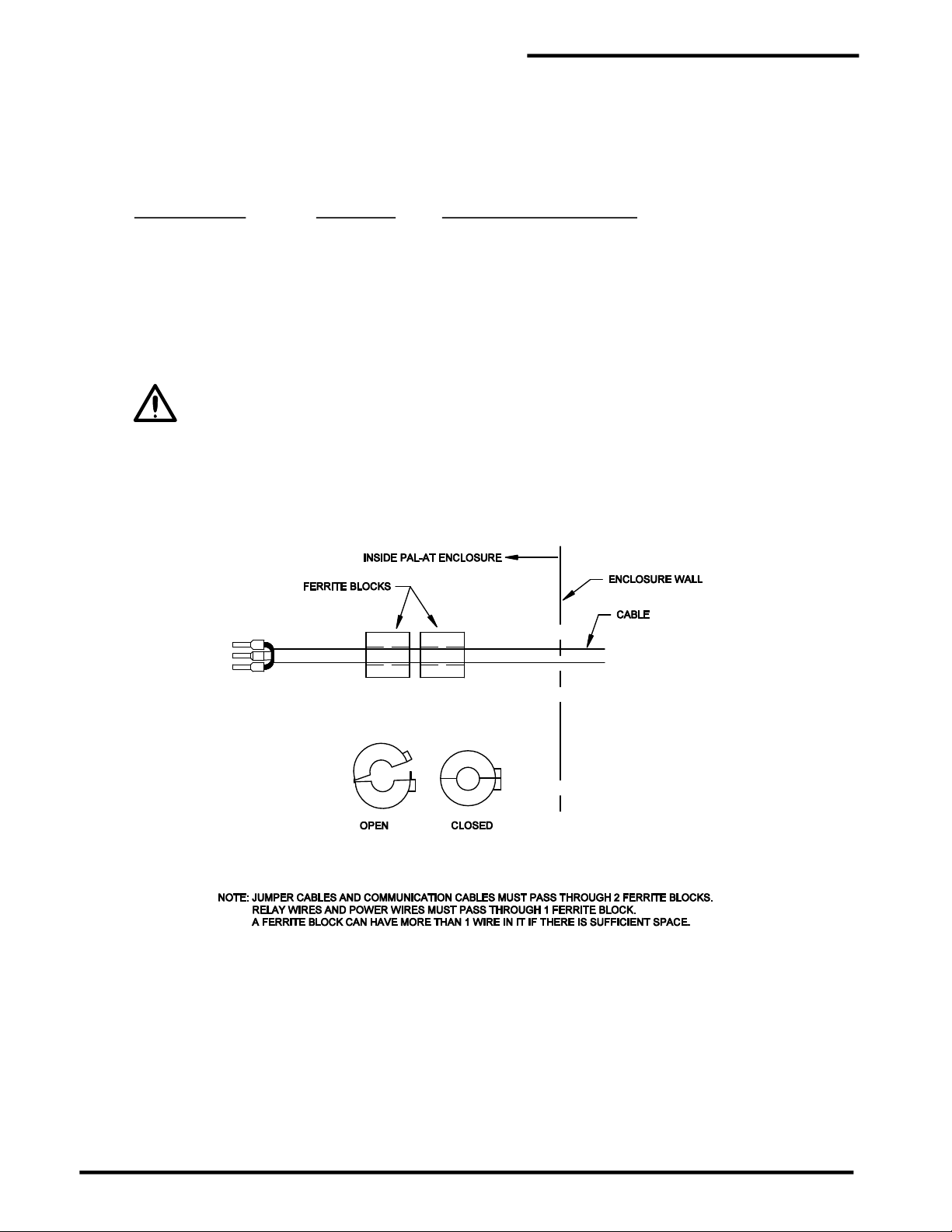
2.11 FCC and CE Compliance Requirements
Each PAL-AT system is supplied with several "ferrite blocks" (PermAlert part # 8058207) to comply with
FCC and CE regulations for a Class A digital device. The sensor cables, jumper cables, and all
communications wires must pass through two blocks before exiting the enclosure (see figure 2-4). All
relay wires and power wires must pass through one block.
PAL-AT Installation Manual
Figure 2-4
Ferrite Block Assembly
16
3.1 Introduction
The optional Zener Barrier Panel (ZBP) is available for connection to PAL-AT when leak detection cables
and probes are installed in hazardous locations. It provides intrinsically safe output circuits for use in Class
I, Division 1 Groups C and D hazardous locations (Zone 0, Group IIB) when used with PAL-AT sensor
cables, jumper cables, and probes, installed in accordance with the instructions in this manual. Refer to
Appendix A, Special Instructions, for intrinsic safety requirements.
The ZBP also functions as a surge suppressor and reduces the chance of damage to the internal Zener
Barrier Assemblies (ZBA) and PAL-AT from external voltage spikes, e.g. nearby lightning strikes.
3.2 Panel Installation
The ZBP is designed to be permanently mounted indoors in a dry, non-hazardous location. The
enclosure is rated Type 4, 12 [IP66] (see figures 3-1, 3-2, and 3.3). The enclosure must not be located in
direct sunlight to prevent excessive heat buildup. In all installations, the ambient temperature
surrounding the panel must not be less than -4°F [-20°C] and not exceed 140°F [60°C]. Relative
humidity must be less than 95% (non-condensing).
The ZBP must be located adjacent to the PAL-AT panel. Each Zener Barrier Assembly (ZBA) in the
panel has a 5 ft [1.5 m] cable connected to the cable plug in the PAL-AT. The cable must be run in
conduit between the two panels.
The jumper cable from the ZBP to the sensing cable in the hazardous location must be routed in
conduit. All conduit fittings must be appropriately rated and installed properly to maintain the rating of the
enclosures. All electrical connections must comply with local codes. Seal-offs may be required to prevent
vapors from traveling into the ZBP.
3 Zener Barrier Panel
Figure 3-1
Zener Panel Mounting
2 PORTS
RS-485/
RS-232
OUTPUT
RELAYS
ZENER
BARRIER
ASSEMBLY
ZBA
PAL-AT Installation Manual
ORDINARY
LOCATION
CLASS I, DIVISION 1, GROUP C
AND D HAZARDOUS LOCATIONS
(ZONE 0 AND 1, IIB).
24 VDC INPUT
DC POWER SW ITCH
USB
+
-
CABLE
CONNECTOR
PAL-AT AT30C/AT75C/AT30K
110-240 VAC INPUT
AC POWER SW ITCH
CABLE TO
ZBP FOR
HAZARDOUS
LOCATIONS
CABLE TO
ORDINARY
LOCATIONS
#1
OPTIONAL ZBP
#4#3#2
1432
3-2
PAL-AT and Zener Barrier Panel
SURGE
SUPPRESSOR
REPLACEMENT
FUSE
CABLE OUTPUT
TO HAZARDOUS
LOCATION
Figure
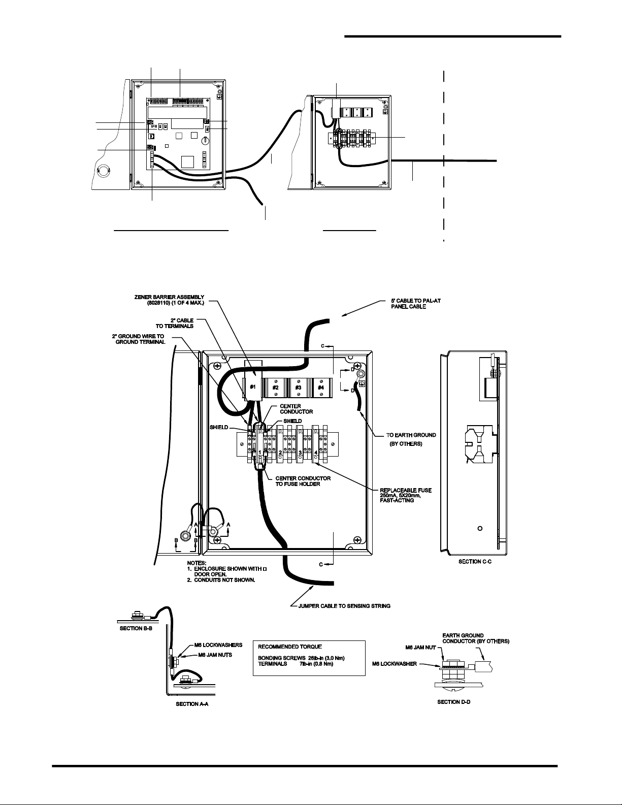
Figure 3-3
Zener Barrier Panel (ZBP) Wiring
18

PAL-AT Installation Manual
3.3 Panel Wiring
The standard Zener Barrier Panel (ZBP) includes one zener barrier assembly (ZBA) and has provisions to
install three additional ZBA’s. Each ZBA has a 2” [50 mm] coaxial cable lead, a 5’ [1.5 m] coaxial lead and
a 2” [50 mm] ground wire.
The 5’ [2 m] cable should be routed through conduit and connected to the appropriate cable plug in the
PAL-AT panel. The jumper cable to the PAL-AT sensing string should be connected to the fuse holder
and adjacent terminal blocks for the appropriate cable number. The jumper cable should have a ferrule
on the center conductor and two ferrules on the braid. Refer to section 8, Cable Connectors, for details.
A customer supplied earth ground wire, minimum 12 AWG [4 mm2], must be connected between
the ground connection on the upper right corner of the white back plate of the enclosure and the
ground bus of the power distribution panel.
3.4 Zener Barrier Assembly (ZBA) Installation
Refer to figure 3-3 to install a ZBA.
1. If an existing ZBA is to be replaced, loosen the four screws on the terminal strip for the ground wire,
coaxial cable center conductor, and two coaxial cable braid wire ferrules. Lift the ZBA out of the mounting
clip. Remove the end of the 5 ft. long cable from the connector in the PAL-AT panel.
2. Position and rotate the new ZBA so the 2” ground wire aligns with the appropriate ground terminal
(green/yellow terminal). Note the ground terminal for barrier #4 is on the opposite side of the fuse holder
as the other barriers. Loosely insert the ground wire, the coaxial center conductor ferrule and two braid
wire ferrules into the ground terminal, fuse holder and adjacent terminals. The ground wire ferrule is a
snug fit in the terminal and may have to be rotated slightly to insert fully.
3. Press and hold the ground wire fully inserted into the ground terminal, while tightening the terminal screw.
Next, press and hold in place the coaxial center conductor ferrule into the fuse terminal and tighten the
terminal screw. Similarly, press, hold and tighten each of the braid wire ferrules. Snap the zener barrier
assembly into the plastic holder. The 5’ [1.5 m] cable should be routed through conduit and connected
to the appropriate cable plug in the PAL-AT panel.
3.5 Fuse Protection
Each Zener Barrier Assembly is protected from external voltage surges by a replaceable fuse in the
terminal strip fuse holder. The 5 x 20 mm fuse is rated 250 mA, 250 V, fast-acting (Littelfuse 0217.250 or
equal). A replacement may be purchased from PermAlert (part # 8067989) or obtained locally.
3.6 Allowable Cables and Probes
Refer to Appendix A – Special Instructions for the PAL-AT control drawing and additional intrinsic safety
requirements for hazardous areas. The following cables, probes, and probe integrators supplied by
PermAlert comply with the allowable electrical characteristics:
Part No. Cable Type Part Number Probe Type Part Number Probe Type
8017705 AGW-Gold 8027888 PHLR-S 8027920 PSTV-L
8017700 AGT-Gold 8027889 PHLR-L 8027633 PTHL-S
8017640 TFH-Gold 8027911 PHLR-P-S 8027970 PTHL-L
8017635 TFH 8027912 PHLR-P-L 8027629 PT10-SC
8017715 JMP-U 8027623 PFS-S 8027932 PT10-SO
8017718 JMP-UD 8027910 PFS-L 8027930 PT10-LC
8017685 JPP 8027624 PSTV-S 8027934 PT10-LO
Note: A PWS probe or a probe integrator connected to a customer supplied probe having an
exposed conductive surface, may not be connected to a ZBA.
19

4 Jumper Cable and Junction Box Installation
4.1 Jumper Cable
1. Jumper cable (types JMP-U, JMP-UD, or JPP) is used to connect sensor cable segments and probes
in series to form the sensing circuit (sensing string). Jumper cable is not affected by occasional contact
with water and can be installed in building and vaults. In underground locations and areas where
damage may occur to the jumper cable, electrical conduit should be used to provide protection. In wet
environments or areas subject to flooding, cable connectors on jumper cable should be located in
watertight electrical junction boxes (NEMA 4 or 4X) [IP66].
2. At least 50' [15 m] of jumper cable (65' [20 m] for type JPP) must be installed from the PAL-AT panel
or Zener Barrier Panel to the first section of sensor cable or probe. An exception is connecting to ATP
cable (see section 10).
3. Table 4-1 lists the length of jumper installed at the very end of a sensing string. A cable connector
must be installed to terminate the end of the last jumper cable section and a threaded plastic cap is
supplied to cover the connector.
4. Refer to section 9, table 9-1 for additional jumper cable required in a probe section.
5. Where possible, jumper cable connections to sensor cable should be made within the monitored area.
PermAlert recommends the use of OZ Gedney, or equal, cord grips installed as shown in figure 4-1.
Cord grips must clamp only jumper cable or TFH cable. The plastic outer braid on TFH cable must be
pulled back so the cord grip is located on the smooth outer jacket.
PAL-AT Installation Manual
6. Check the cable/connector assembly with an ohmmeter in accordance with the cable testing
procedures contained in this manual.
7. The recommended minimum bend radius for all jumper cables is 1.5” [38mm].
Table 4-1
End of System Jumper Cable Length
System Length
ft / [m]
0–2500 / [0-750] 30 / [9] 40 / [12]
2500-5000 / [750-1500] 50 / [15] 65 / [20]
5000-7500 / [1500-2300] 100 / [30] 125 / [40]
JMP-U/UD
End Jumper Length
ft / [m]
End Jumper Length
JPP
ft / [(m]
20
PAL-AT Installation Manual
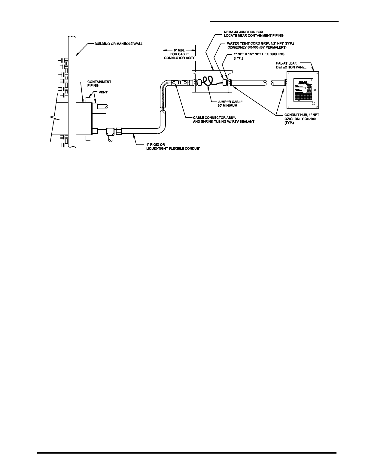
Figure 4-1
Typical Cable Connection in Monitored Areas with Junction Boxes
4.2 Calibration Points
1. During the initial setup and calibration of the PAL-AT system, connectors at selected locations
(calibration points) are temporarily disconnected. Therefore, it is imperative to have accessibility
to connectors at calibration points at all times until the system is brought on-line.
2. Reported fault location accuracy of the first leak is dependent upon the use of and distance between
calibration points. Calibration points are required at changes of cable types unless connected to short
lengths of jumper cable (15' [5 m] or less). Additional calibration intervals of 500' [150 m] or less will
result in location accuracy of within +/- 6' [2 m]. Systems installed with calibration intervals exceeding
500' [150 m] will have a location accuracy of less than +/- 1% of the cable length from the previous
calibration point.
4.3 Junction Boxes
There are two series of junction boxes supplied by PermAlert. The standard, polyester box has a
maximum temperature rating of 150°F [65°C]. A fiberglass box is available for temperatures to 300°F
[150°C].
1. Locate and install all junction boxes before installing any cable. Locate junction boxes as indicated on
system drawings or as required. These locations include calibration points, the start and end of cable
runs, manholes, probes, etc. Care must be taken to prevent water from contaminating these areas.
2. Securely mount the junction boxes to a vertical wall. In manholes or pits that might collect and hold
water, mount junction boxes as high as possible. Use NEMA 4X [IP66] junction boxes at all locations.
3. Use a hole saw to cut the junction box as needed for conduit.
4. When jumper cable is installed in electrical conduit, use watertight conduit hubs and cord grips at
junction boxes. Discard the male bushing supplied with the hub and use the cord grip supplied in its
place. Depending upon the specific products used, a lock nut may be required on the cord grip's
threads to pull the hub tight to the wall of the junction box.
Caution: Always keep junction boxes and electrical conduits capped to prevent water from
entering.
21

PAL-AT Installation Manual
5 Cable Installation in Secondary Contained Piping
5.1 General
In secondary contained pipe applications, the sensor cable is installed in the bottom (6 o’clock position) of
the air space between the product pipe(s) and secondary containment (outer casing or conduit). The leak
detection cable is a sensitive sensor, capable of detecting small amounts of liquid. Therefore, every effort
must be made to keep the cable dry and prevent water from entering the air space. In addition,
long-term accumulations of water, corrosive liquids, or hydrocarbon liquids in the containment
pipe may degrade the containment or the leak detection system components. The piping system
must remain sealed during installation to prevent moisture entering the system. The installing contractor
must install caps on the open ends of pipe installed in a trench to prevent liquids from entering the conduit
or containment pipe.
Caution: A heated system using mineral wool or fiberglass insulation should be carefully
monitored during startup. If the insulation is wet (even from atmospheric moisture) prior to
startup, the water may combine with the ammonium sulfate binders in the insulation and release
ammonia when the pipe is heated. The ammonia is detrimental to the leak detection cable and
may be detrimental to the piping system if left uncorrected.
If the system becomes wet, it must be completely dried. Drying methods can consist of pulling a vacuum
on the interstitial space, using compressors with desiccant dryers, or other methods. Obtain guidance
from your piping supplier on proper techniques to be used with your system.
This section is intended to cover installation methods typically employed with any fabricated secondary
contained pipe systems. Typically, these manufactured products are custom fabricated with product pipes
positioned by specially designed supports within the secondary containment. All pipe supports and
changes in direction must have guides constructed out of stainless steel, minimum ¾" [20 mm] ID
tubing, with flared ends. Plastic supports must be avoided when the carrier pipe is metal. Consult
with the piping system manufacturer before installation to ensure provisions are being made for
the cable installation. Because the sensor cable installation is dependent upon the design provisions
employed by the pipe manufacturer, it is recommended the secondary pipe manufacturer supply the leak
detection/location products. This sole source responsibility will greatly facilitate proper installation with
lower cost.
The following charts are general references for installing a sensor cable into field-constructed secondary
contained pipe system built with piping components. Typically, these systems are constructed using
standard lengths of pipe and fittings for the product and secondary containment structures. Components
of the piping system should be designed, manufactured, and installed to facilitate sensor cable installation.
Because the sensor cable is placed on the bottom of the air space, there must be a continuous
unobstructed passage for the cable(s) being pulled into the system. PermAlert recommends a 1" [25
mm] air space. Pipe support design and alignment is critical. Pipe supports and other surfaces
the cable contacts during “pulling” operations must be smooth to prevent snagging or damaging
the cable.
Field joint designs and procedures employed in the installation of the piping system must prevent
damage to the pull rope and/or sensor cable.
Pull ropes must be installed as the pipe system is assembled together to facilitate the installation. Special
stainless steel ¾" [20 mm] ID guide tubes must be installed in the air space of the containment straight,
elbows, tees and wyes (lateral) at the factory. Pull points must be designed and provided at specific
locations to facilitate the installation of the pull cable and leak detection cable. The recommended
minimum bend radius for all sensor and jumper cables is 1.5” [38mm].
Leak Detection Sizing Chart
22

PAL-AT Installation Manual
Pipe Size
(in) [mm]
Casing Size
(in) [mm]
SDR11/SDR11
SDR11/SDR32.5
Polypropylene / Polyethylene Piping SDR Sizes
1.5 [40] 4 [100] OK OK
2 [50] 6 [150] OK OK
3 [80] 6 [150] OK OK
4 [100] 8 [200] OK OK
6 [150] 10 [250] OK OK
8 [200] 12 [300] OK OK
10 [250] 14 [350] NO OK
12 [300] 16 [400] N/A OK
14 [350] 18 [450] N/A OK
16 [400] 20 [500] N/A OK
Leak Detection Sizing Chart
For Standard Weight Steel and Fiberglass Pipe
(w/o insulation, 10 gauge steel or fiberglass containment)
Note:
1. Not all pipe types or sizes are shown in the above charts. For different systems,
contact PermAlert.
2. Chart is based on smooth pulling surfaces and installation of guide tubes.
3. Multi pipe system will require factory sizing.
5.2 Pull Points
1. Sensor cable must be “pulled” into the monitored areas using a continuous pull rope free of splices
between pull points. Surfaces the cable contacts during “pulling” operations must be smooth to prevent
snagging or damaging the cable.
2. Generally, pull points can be located at 500' [150 m] intervals for straight runs. Each 90° fitting on the
run reduces the interval by 150' [50 m]. For example, a run of 50' [15 m] with three elbows is allowable
(500' - (3 x 150') = 50').
Pipe Size (in) [mm] Casing Size (in) [mm]
2 [50] 6 [150]
3 [80] 6 [150]
4 [100] 8 [200]
6 [150] 10 [250]
8 [200] 12 [300]
10 [250] 14 [350]
12 [300] 16 [400]
3. Pull point designs should be selected not only based on accessibility during installation, but potential
future cable replacement. When future cable replacement is a consideration, it is recommended
underground installations have watertight junction boxes or secondary contained access points
installed at grade or in vaults (see figure 5-1).
Caution: Pulling points often become calibration locations. When this occurs, accessibility
to the cable connectors is necessary during the initial commissioning of the PAL-AT and
the system’s setup procedures.
23

PAL-AT Installation Manual
4. Pull ports may also be used for periodic testing. If so, a short length of sensor cable (minimum 5’
- AGW-Gold, 15’ – TFH/TFH-Gold) with connectors should be installed in the pull port during the initial
setup. It is used as a test piece and can be replaced if needed after testing without setting up the
cable string again.
Figure 5-1
Detail of Pulling Point
24

PAL-AT Installation Manual
5.3 Cable Splices
Continuous pull rope and sensor cable are "pulled" into the secondary containment during certain stages
of installation. Several splices are used to provide secure attachments to pull ropes and cable during this
procedure. The following methods are recommended for splicing.
Note: When using tape to seal the splices, use only PVC electrical tape. PVC tape minimizes drag on the
cable and reduces snags.
5.3.1 Factory Installed Fiber Pull Rope to Continuous Pull Wire Rope Splice
Step A Extend 12" to 18" [300 mm to 450 mm] of fiber rope and 14" to 20" [350 mm to 500 mm] of wire
rope.
Step B Wrap a small amount of electrical tape around the fiber rope's end to prevent unraveling. Using a
small pointed object (such as a nail), slightly separate the fiber rope braid and weave the wire rope
into each opening of the braid as you go.
Step C Pull the wire rope tight, as it is woven into the braid.
Step D Using electrical tape, wrap the entire length of the splice area. The tape should extend
approximately 2" [50 mm] over each end of the splice.
25

5.3.2 Wire Rope to Wire Rope Splice
Step A Extend 12" to 18" [300 mm to 450 mm] of each wire rope end for the splice.
Step B Unravel each of the 12" to 18" ends into a 3-strand and a 4-strand section (approximately 50% in
each), keeping the adjacent strands together.
Step C Starting approximately ¼" to ½" [6 mm to 12 mm] from the start of the wire rope's split, intertwine
a section from each of the two ropes.
PAL-AT Installation Manual
Step D Line up the two remaining sections and intertwine them together in a similar manner. In order to
minimize the size of the splice, make sure the starting points for each intertwining operation line
up with each other.
Step E Starting at approximately 1" [25 mm] from the beginning of the splice, wrap electrical tape around
the splice until the entire splice, plus 1" on each end, is covered. Normally only one wrap is
needed. Make sure both ends of the tape wrap are tapered and smooth in case the pull direction
must be reversed.
26

5.3.3 Wire Rope to Wire Rope Splice (alternate)
Note: Use this splice when splicing two different size wire ropes together
Step A Extend 8"-10" [200 mm to 250 mm] of each wire rope to be spliced.
Step B Unravel each of the 8"-10" sections (to approximately the same length) into two sections to form
a Y with three adjacent spiral strands on one side, three adjacent spiral strands with center strand
on the other.
Step C Taking one end of the first cable, fold over the 4-strand section of the Y to form a loop. Join the
3-strand section to the 4-strand section. Wrap the 3-strand section around the 4-strand section
so the strands appear as in the original undisturbed cable.
PAL-AT Installation Manual
Step D Take the second cable Y end and place the 4-strand end through the eye of the first cable loop.
Step E Repeat steps A through C.
Step F Using a pair of pliers, crimp the ends of the loops.
Step G Spiral wrap the splice tightly, using electrical tape.
27

5.3.4 Wire Rope to Leak Detection Cables
The following steps apply in general to all sensor and jumper cables. However, there may be slight
variations to the steps presented depending on the cable selected. For example, the jumper cables have
an outer jacket but no plastic overbraid, while the TFH cable has both a jacket and an overbraid.
Step A Extend the 7-strand 1/8" [3 mm] wire rope for splicing. Cut the end so all strands are even.
Step B Unravel 8" [200 mm] of the wire rope into two sections to form a "Y" with three adjacent spiral
strands on one side and four strands on the other side.
PAL-AT Installation Manual
Step C Extend approximately 5' [1.5 m] of cable for the splice. Form a small loop in the shape of a "U" 5'
from the end of the cable and tape it in place tightly. Do not kink the cable when forming the "U"
(Skip this step with jumper cables.)
Step D Cut the end of the cable so the plastic overbraid, jacket, metallic braid, center conductor insulation,
and center conductor are flush at the end of the cable.
Step E Slide the plastic overbraid back over the sensor cable at least 24” [600 mm] and tape in place
tightly.
28

PAL-AT Installation Manual
Step F Cut 5" [125 mm] off the exposed end of the sensing cable.
Step G Cut off 15"-18" [380 mm to 450 mm] of the outer jacket and tightly tape the edge of the outer jacket
to the metallic braid. (This applies to only TFH and jumper cables.)
Step H Slide 12" [300 mm] of the metal braid back towards the taped jacket. Tape the metallic braid in
place.
Step I Cut 4" [100 mm] off the end of the center conductor and conductor insulation.
Step J Carefully remove 6"-8" [150 mm to 200 mm] of the dielectric spacer material and conductor
insulation from the center conductor. Do not cut the center conductor strands when removing the
thin film of insulation. Securely tape the end of the dielectric spacer to the center conductor.
Step K Insert 1" [25 mm] of the cable's center conductor into the throat of the wire rope.
Step L Carefully braid 1" of the 3 and 4-strand sections of the wire rope.
Step M Insert the center conductor of the cable into the next section of the Y throat of the wire rope.
Continue to wrap and insert until approximately 5"-7" [125 mm to 175 mm] of the cable center
29

PAL-AT Installation Manual
conductor is woven into the wire rope. Tape the end of the wire rope with electrical tape. Cut off
excess wire rope at the end of the splice if necessary.
Step N Spirally tape the entire spliced wire rope/center conductor area tightly from front to end.
Step O Carefully slide the metallic braid over the woven splice area making sure the braid extends over
the splice as much as possible, and is tight.
Step P Tightly tape the metallic braid in place, from the left end. Extend the tape just past the woven
splice area. (Include 2”-3" [50 mm to 75 mm] of the white jacket if applicable.)
Step Q Carefully slide the plastic overbraid over the cable splice. Extend the plastic overbraid over the
splice area as far as possible.
Step R Tightly tape the plastic overbraid in place, spirally, from the front end. Extend the tape just past
the spliced area. The finished splice should be tapered in appearance.
5.4 Installation of the Continuous Pull Rope
1. PermAlert recommends the installation of a continuous pull rope, free of splices between properly
located and accessible pull points.
2. All sections of factory-prefabricated piping should be supplied with a factory-installed pull rope. The
factory-installed ropes shall be used to pull the continuous pull rope into the air space before the
secondary containment field joint closures are completed. Make sure the factory installed pull rope
moves freely in each section of conduit when laying the pipe in the trench.
3. Pulling the continuous pull rope into the air space of the secondary containment requires careful
planning on the installer’s part. Care must be taken during the installation of the pipe system to
proceed in a manner to maintain accessibility to the factory installed pull rope.
4. The installation of the continuous pull rope and the pipe system must proceed simultaneously.
Working ahead on closing the pipe system joints may prevent the successful installation of the pull
rope, necessitating the reopening of a joint(s). Avoid allowing water, mud or other debris from
entering the air space. This can prevent successful cable pulling and a functional system.
30

PAL-AT Installation Manual
5. Caution all workers involved in the pipe installation that the factory installed pull rope should
never be “temporarily” removed with the expectation it can be replaced later. Losing the end of
the pull rope and allowing it to fall back inside the secondary containment must be avoided. Special
care must be taken at risers where the weight of the rope, in the vertical section of the pipe, tends to
pull the rope into the secondary containment.
Step A Splice the continuous pull rope to the factory installed pull rope. Follow splicing procedures
contained in the “Cable Splices” section.
Step B Go to the first uncompleted secondary containment field joint and pull the continuous pull rope into
the first section of piping until the splice exits the field joint.
Step C Break the splice on the factory installed pull rope and discard the pull rope. Splice the continuous
pull rope to the next section of factory pull rope, and pull the continuous pull rope into the next pipe
Step D Return to the first field joint. If the product pipes are insulated, apply insulation material. To
prevent the continuous pull rope from being damaged during joining of the secondary containment,
it must be held off the bottom of the containment. Attach the pull rope temporarily to the carrier
pipe (insulation) by looping a piece of 22 gauge steel wire around the carrier pipe (insulation) and
twisting the ends together to form a hook around the pull rope.
31

PAL-AT Installation Manual
Step E The secondary containment field joint can now be made. After closing the field joint of the
secondary containment, restrain the continuous pull rope at the spool end, and pull on the rope at
the open field joint in order to pull the rope off the wire hook.
Step F Pull the continuous pull rope from the previously sealed joint to the next open field joint.
Step G Repeat the sequence of splicing, pulling and closing the field joints of the secondary containment
until the continuous pull rope has been pulled through the entire piping run. Each time after
completing 3 or 4 field closures, move the continuous pull rope back and forth in the containment
to insure the pull rope moves freely.
5.5 Installing Sensor and Jumper Cables
1. After all other work is completed and the area is free and clear of all activities that can cause damage,
the sensor cable should be installed. Care must be taken during installation of sensor cable to
avoid contact with potential contaminants such as water puddles or oil.
2. PermAlert recommends installing the sensor cable before backfilling of underground secondary
contained pipe systems.
3. Keep the cable dry and clean. Tent the spool area and do not install the sensor cable during a
rainstorm.
4. Slowly play out the cable by hand rotating the spool. Never attempt pulling loose coils of cable off the
end of the spool. When loose coils are pulled taut, kinks may form that could prevent bringing the
system on-line.
5. Always be careful to prevent the cable from falling into the secondary containment. Be
particularly careful at risers, where the weight of the cable in the vertical section of pipe tends to pull
back the cable.
6. The bottom of a secondary containment that penetrates into a vault or building should be fitted with a
minimum 1" [25 mm] threaded pipe coupling or similar fitting. This fitting will be located where the
sensor cable enters (exits) the secondary contained piping system.
7. Check that the air spaces of secondary containment, at termination points of the piping system, are
dry. Drain plugs in the containment should be provided for this purpose. If water is found, dry the
system completely before attempting installation of the sensor cable.
8. Place the spool of sensor cable at the high end of the run. At this time, do not route the pull rope or
32
PAL-AT Installation Manual
cable through the junction box and conduit.
9. Splice the sensor cable to the continuous pull rope using the method described in section 4.3, "Cable
Splices".
10. At least two workers are required to pull sensor cable. Work should proceed continuously from pull
point to pull point. At the lowest elevation between two pull points, one person should slowly pull on
the pull rope. At the higher elevation pull point, the second person should carefully play out the cable
while pushing it into the interstitial air space. This push/pull action significantly reduces the pulling
force required to install the cable. If a problem does arise, the workers must be able to signal each
other quickly. Walkie-talkies are recommended so communication can occur to prevent cable damage.
11. The pulling force should never exceed 50 lb [23 kg]. If a snag is encountered, carefully work the
cable back and forth in an attempt to clear the cable. If the snag cannot be cleared, contact PermAlert's
Field Service Department for assistance.
12. Where electrical conduit and junction boxes are required, use watertight NEMA 4X [IP66] boxes and
mount per the instructions contained in this guide. Temporarily pull enough sensor cable out of the
secondary containment and into the junction box (approximately 2' [600 mm]) to allow installation of
cable connectors (see figure 5-2). Make sure the bushings and cord grips are slipped on the
jumper cable before installing the cable connectors. Attach the cable connectors, test them, and
push the assemblies into the electrical conduits. Thread and tighten the cord grips making a watertight
seal against the jumper cable. The conduit termination points must be sealed. Do not leave conduit
termination points open, or moisture may enter and wet the sensor cable.
13. The ends of all cables should be kept dry during installation. If the cable ends are submerged
in water, capillary action will wick water into the center conductor. This could cause corrosion
and shorten the life of the cable.
14. If TFH cable is installed, the ends of the cable must be immediately sealed with the shrink tube
caps supplied by PermAlert to prevent water from entering the cable under the jacket. Make
sure the polyester overbraid is not under the shrink cap to insure a good seal. If water is allowed to
enter the ends of TFH cable, it must be replaced.
Figure 5-2
Cable Connections with Electrical Conduit and Junction Boxes
15. In contained pipe systems where branch runs and main runs are monitored, jumper cable can be used
to return to the main from the branch. For these installations, PermAlert can furnish a cable routing
33

PAL-AT Installation Manual
drawing showing locations requiring the installation of sensor cable and jumper. Depending on the
design of the secondary contained system and the free unobstructed air space available, both cables
(sensor and jumper) may be installed in the secondary containment air space. This will require
simultaneously pulling both cables, and most likely will reduce the length of cables that can be pulled
at one time. When 2 cables are installed in the same air space, both cables must be pulled out of the
secondary containment through the threaded coupling and finally connected together with a cable
connector in either: (1) a watertight capped pipe chamber connected to the threaded coupling, as
shown in figure 5-3 or (2) a NEMA 4X [IP66] junction box. This type of termination should also be
accessible to allow for future maintenance. As an alternative to pulling both cables into the air space
of the secondary containment, jumper cable can be routed in electrical conduit. If connectors must be
used, it is recommended they be installed in accessible watertight NEMA 4X [IP66] junction boxes
located at grade.
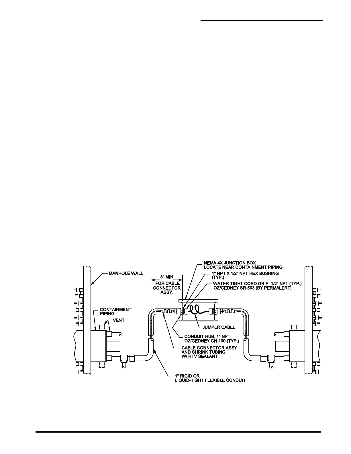
Figure 5-3
Branch Line Routing of Jumper Cable
16. At least 50' [15 m] of jumper cable must be installed from the PAL-AT panel before connection to
sensor cable. Refer to table 1 (see section 3) for jumper installed at the very end of a sensing string
in an enclosure (see figure 5-4). A cable connector must be attached to terminate the end of the
jumper cable. Install the red plastic cap supplied with the PAL-AT, over the connector to keep it clean.
The termination of the sensing string should be accessible for future maintenance.
Figure 5-4
Termination of Sensing String
34

5.6 Air Testing
1. Air testing of the secondary containment must be performed before backfilling.
2. All sensor cable termination chambers (see figures 5-3 and 5-4) must be completely installed before
applying the air test. Also, cap any open vents or drains. Be careful to prevent the pull rope or sensor
cable from being blown back into the secondary containment.
3. Assemble required piping for air test and follow test procedure provided by the secondary containment
piping manufacturer's installation guide.
CAUTION: THE COMPRESSED AIR SUPPLY MUST BE FREE OF WATER AND OIL.
4. After the air test has been completed, remove test piping and cap test ports on the secondary
containment.
PAL-AT Installation Manual
35

6 Installation of Direct Buried Sensor Cable
6.1 General
The following instructions and precautions are very important for the successful installation and operation
of the PAL-AT system with direct buried sensor cable. These instructions do not cover every possible
situation, but are intended as guidelines for the majority of applications. Remember, the sensor cable is a
sensitive electrical cable and should not be crushed, stretched, kinked, cut or damaged. If you have any
questions regarding the installation of the direct buried cables, contact PermAlert. Failure to follow these
instructions may result in damage to the cables or its jacket and prevent or limit operation of the PAL-AT
system.
1. TFH and TFH-Gold cables are constructed of materials that detect hydrocarbon liquids, but ignore the
presence of water. TFH cable has an outer jacket to protect the nickel-plated, copper braid wire. TFHGold cable does not have an outer jacket, but uses polymer-coated braid wire that is corrosion
resistant.
2. These unique sensor cables can be installed in wet soil environments while monitoring for the leakage
of hydrocarbon liquids. This feature permits direct burial of TFH/TFH-Gold, in 1½” or 2” “screened” or
slotted PVC pipe, for the monitoring of underground single wall piping and tanks. The maximum burial
depth of TFH/TFH-Gold cables is 20' [6 m]. This limitation is due to the fact the cable materials repel
water to a maximum pressure of 8.7 psi [0.6 bar]. If the cable jacket (TFH) or cable core (TFH-Gold)
is damaged, water may enter the cable and prevent or limit the operation of the PAL-AT system.
PAL-AT Installation Manual
3. The location of the slotted pipe and hydrocarbon detection cable is determined by several variables.
These variables include soil type, backfill material, product in the pipeline, water table, pipeline
pressure and leak rate. Another consideration is if the installation is new or a retrofit of an existing
pipeline.
4. It is recommended to slide a fabric sleeve or sock liner over the slotted PVC pipe to minimize soil
entering and possibly blocking the pipe after an extended time. A 3” sleeve is typically available in
home improvement stores and other sizes are available at industrial sources.
5. The sensor cables must be located where the hydrocarbon liquids will collect and allow detection. For
some applications, the use of a closed synthetic liner, installed in the pipe trench, may be considered
to facilitate the collection of hydrocarbon liquid for detection and reduce soil contamination. Normally
one cable located in a slotted pipe adjacent to an underground pipe will provide satisfactory results.
The slotted pipe may be located under the service pipe for a new installation. If the system is installed
with an existing pipeline, the slotted pipe can be installed a few inches to the side of the pipeline to
minimize the excavation cost.
6. If buried TFH/TFH-Gold is submerged in water and the water freezes, the resulting compression of the
cable may be detected as a leak and cause an alarm. This effect should be considered when
determining the placement of the cable to reduce false alarms. It does not damage the cable.
7. The recommended minimum bend radius for all sensor and jumper cables is 1.5” [38mm].
36

PAL-AT Installation Manual
8. If a synthetic liner is not installed under the slotted pipe, a compacted clay/silt base layer should be
used under the pipe to minimize the vertical migration of a leak. The slotted pipe should be covered
with backfill material of sand or soil.
9. It is recommended to have 12” [300 mm] inches of backfill installed and compacted with hand tampers
above the slotted pipe before mechanical compactors are used, to prevent crushing the pipe.
10. During the storage and installation of TFH cable, the ends of the cable must be protected to keep water
from entering. The cable is shipped with shrink tube caps on the ends. Additional caps are supplied
with TFH connectors to be installed on the cable temporarily until the connectors are installed. The
caps should be installed over the jacket, but under the outer plastic overbraid of the cable. The cable
ends should not be immersed in water at any time, even with the shrink caps installed. After the
connectors are installed, if there is any possibility of water contacting the connectors, they should be
sealed with non-corrosive RTV and shrink tubing immediately. If the connector needs to be reopened
later for calibration, slit open the outer shrink tubing. Replace it with a new shrink tube immediately
after calibration. Shrink tube caps are not required for TFH-Gold.
11. The sensor cable must be protected from damage when it is in the trench before backfilling. The cable
must be protected when pipes are being welded or other work is occurring nearby. The cable should
not be stepped on.
12. All connectors of sensor cable must be located in junction boxes at or above grade. A vertical riser of
PVC conduit or other material suitable for the project must be installed to provide protection to the
cable through the backfill and into the junction box (see figure 6-1). Follow the instructions for installing
cable connectors using shrink tubing and RTV sealant to insure a watertight assembly.
CAUTION: It is extremely important to prevent damage to the TFH cable jacket. A damaged
cable must be replaced.
6.2 Installing the Sensor Cable
1. After all other work is completed and the area is free and clear of all activities that can cause damage,
the sensor cable should be installed.
Care must be taken during installation of sensor cable to avoid contact with potential
contaminants such as oil, hydrocarbon liquid, soap or other material that may contain
surfactants. Contamination by any of these liquids will destroy the water repellency of the
cable and it will need to be replaced.
2. When the construction schedule allows, the PAL-AT panel should be permanently mounted and
connected with electrical power before installing jumper or sensor cable. This will allow the system's
setup and calibration procedures to proceed efficiently. For additional information on calibration points,
refer to the PAL-AT Operating Manual.
3. Slowly play out the cable by hand rotating the spool. Never pull loose coils of cable off the end of the
spool. When loose coils are pulled taut, kinks form in the cable that could prevent bringing the system
on-line. Protect open ends of the cable from damage, contaminants and moisture.
4. Starting from the panel, connect a minimum of 50' [15 m] of jumper cable before connecting the sensor
cable. Route the sensor cable as shown on the contract drawings. Refer to table 1 (see section 3) for
amount of jumper cable to be connected to the end of the sensing string.
5. Make sure all TFH cable ends are sealed with shrink tubing after installation.
37

PAL-AT Installation Manual
Direct Buried TFH/TFH-Gold Hydrocarbon Sensor Cables
Figure 6-1
38
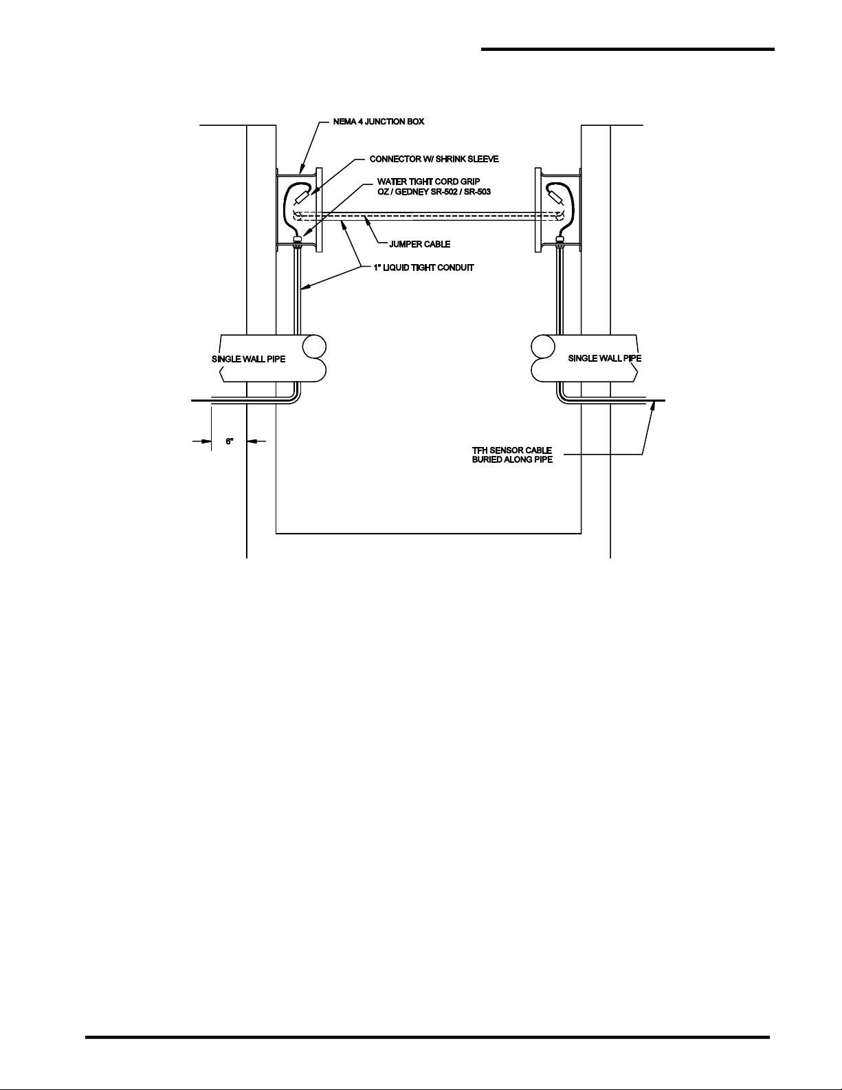
PAL-AT Installation Manual
Figure 6-2
Hydrant Valve Pit / Manhole Penetration
Direct Buried Cable
39

6.3 Above Ground Storage Tanks
Above ground storage tanks can be monitored for leaks by installing TFH/TFH-Gold sensor cable in slotted
PVC pipe under the bottom of the tank or around the perimeter. Figures 6-3 and 6-4 show two such
applications. For specific applications, contact PermAlert for assistance.
PAL-AT Installation Manual
Figure 6-3
Double Bottom Above Ground Storage Tank
40
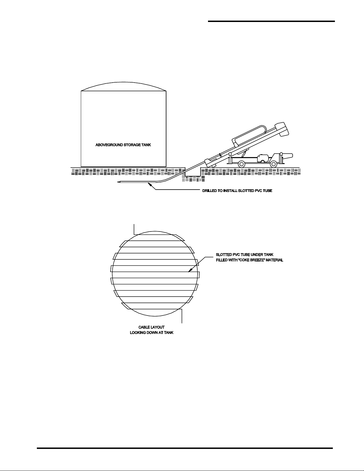
PAL-AT Installation Manual
Above Ground Storage Tank Horizontal Drilling
Figure 6-4
41

7 Cable Installation for Raised Floor and Ceilings
7.1 General
The PAL-AT sensor cables can be installed in ceilings above drop ceilings or on subfloors below raised
flooring to detect water, hydrocarbons, or chemical liquids. AGT-Gold responds quickly to thin films of
liquid. AGW-Gold allows a small accumulation before detecting a leak and dries quickly after removal of
the liquid. AGW-Gold was tested and passed UL910 for Plenum applications. AGW-Gold is the preferred
selection unless the application requires wicking of the liquid for detection of small liquid leakage.
The AGT-Gold sensor cable has a polypropylene yarn dielectric and is designed to absorb liquids readily
and detect leaks quickly. It also absorbs moisture from the air if the air is saturated or near saturation.
PermAlert recommends a maximum of 80% relative humidity, keeping in mind the relative humidity will
increase if the temperature of the air or a surface in the airflow decreases. In subfloor applications, care
must be taken to make sure the cable is not located directly in the airflow where localized higher humidity
or saturated air is present.
If the humidity level cannot be controlled and intermittent high humidity conditions exist, then the best
option is to use the quick-drying AGW-Gold cable in place of the wicking AGT-Gold cable.
7.2 Install the Sensor Cable
1. After all other work is completed and the area is free and clear of all activities that can cause damage,
the sensor cable should be installed. Care must be taken during installation of the sensor cable to
avoid contact with potential contaminants, such as water puddles or oil.
PAL-AT Installation Manual
2. When the construction schedule allows, the PAL-AT panel should be permanently mounted and
connected with electrical power before installing jumper or sensor cable. This will allow the system's
setup and calibration procedures to proceed efficiently. For additional information on calibration points,
refer to the PAL-AT Operating Manual.
3. Slowly play out the cable by hand rotating the spool. Never pull loose coils of cable off the end of the
spool. When loose coils are pulled taut, kinks form in the cable that could prevent bringing the system
on-line. Keep the cable dry and clean.
4. Starting from the PAL-AT panel, connect a minimum of 50' [15 m] of JMP-UD jumper cable (65' [20 m]
for type JPP) before connecting the sensor cable. Route the sensor cable as shown on the contract
drawings. Most designs require the sensor cable to be installed in a serpentine pattern of 4' [1.2 m]
centers. Normally, this method gives satisfactory protection and does not require the cable to be
repositioned when equipment is moved later. Typically, centers of 6’ to 12’ [2 m to 4 m] can be used
if the facility has low risk (see figure 7-1).
5. If the serpentine pattern cannot be adapted to the installation, an alternative is to isolate the potential
leakage areas. Typically, this means running the sensor cable around the perimeter of the room and
placing a run of cable under or near any water lines or drains in the room's interior. The sensor cable
should be routed around air conditioning units and chillers so an overflow from a plugged condensate
tray must pass the sensor cable before it can reach power or data cables.
6. The sensor cable should not be routed directly in the airflow from an air-handling unit, especially if a
humidifier is being used. In this case, the unit may send out drops of water that can collect in the cable
and give an alarm for a minor puddle.
This is more critical with AGT-Gold cable. The wicking nature of the cable will absorb the fine spray
from the humidifier and cause an alarm. Typically, the cables are 3' to 5' from the perimeter of the air
units.
7. Refer to table 1 (see section 3) for amount of jumper cable to be connected to the end of the sensing
string.
8. Cables are attached to the subfloors and ceilings with fasteners (cable mounts). Normally, cable
mounts are spaced on 8' [2.5 m] intervals along the sensor and jumper cable length. Additional cable
mounts are located adjacent to all changes in direction of the sensor cable.
42

PAL-AT Installation Manual
9. Cable mounts (CMA) ordered from PermAlert are adhesive backed. When installations require
mounting to unsealed concrete surfaces, it is recommended construction mastic be used. Care must
be taken to ensure the mastic does not touch the sensor cable. This material can be purchased from
most supply houses. Inspect subfloor (or ceiling) surfaces to be sure it is clean and dry before
beginning installation. Cable tags (CTA) are typically installed on 50' [15 m] intervals for location
purposes.
10. In high traffic areas, cable shields should be used to protect the cable from damage.
11. Service loops (slack cable) should be positioned at connector locations.
12. If the cable is going to be installed in a location that will have limited or challenging access, it is
recommended test ports be installed in a serviceable location for calibration and functional testing.
See section 7.4 for further details.
Figure 7-1
Computer Room Floor
7.3 Locator Chart
A graphic display map drawn to scale shall be prepared by the contractor (installer) after completion of
installation from "as built" drawings. The map shall indicate, in relation to the raised floor grid, the location
of the cable, connectors, and landmarks (such as equipment, walls, and drains). Cable distance readings
shall be marked off in 100' [30 m] (or other suitable) increments, beginning at the monitoring panel, to
facilitate physically locating a leak detected by the system. The locator chart should be placed in a plastic
frame suitable for permanent mounting adjacent to the PAL-AT panel.
7.4 Calibration and end of run Access Points
In the event the cable will be inaccessible or in a location where access will be limited or challenging, it is
recommended that calibration points be added. Calibration points shoud be brought to an easily
serviceable location every 500 feet or at the end of serpentine runs along a wall where the cable returns
in the opposite direction. To create a calibration point, jumper cable is run to an accessible junction box to
a 10’ length of sensor before returning to jumper cable back to the main cable run. The 10’ sensor cable
can be used as a calibration and testing point to validate cable lengths and functionality when the main
cable cannot be accessed. At minimum, it is recommended that the end of the cable run be installed in an
accessable location to give a validation point for cable length.
43
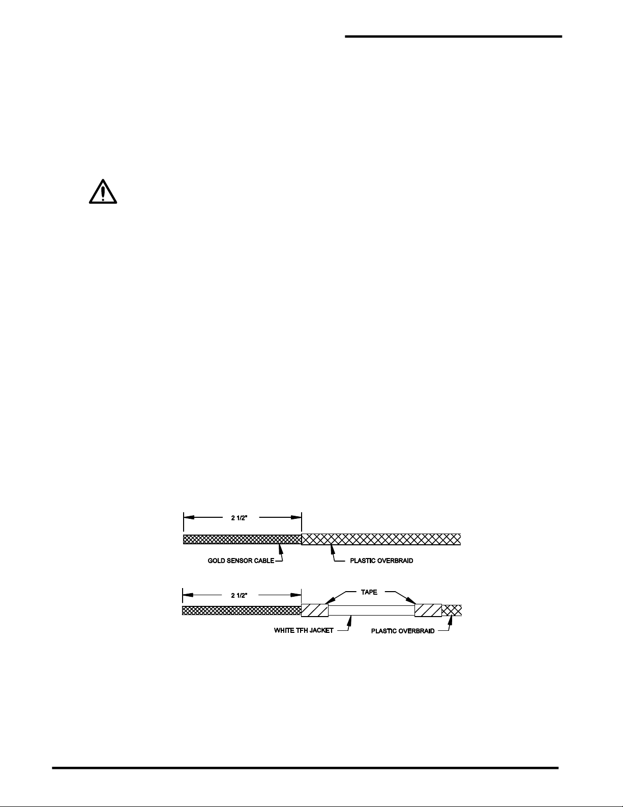
8 Cable Connectors
8.1 General
This section outlines: (1) the installation procedures for several types of connectors; (2) the application of
shrink tubing; and (3) the electrical testing of connectors and cable. All connectors are crimp style and
soldering is not required.
Instructional videos for Cable Connector Installations are available at the PermAlert web site,
www.permalert.com.
WARNING For Hazardous Locations – Some cable connectors are located in NEMA 4X [IP66]
junction boxes that are made of plastic and as such, present a possible electrostatic hazard. They
are not intended to be cleaned, but if they are, a damp cloth should be used.
8.2 Cable Connector Installation
1. Cable connectors must be installed at changes of cable types, pull points, junction boxes, calibration
points, and at the termination of the sensing string.
2. All the PAL-AT cables, except ATP, are coaxial construction consisting of an insulated center conductor
and a braid shield. Jumper cables and TFH sensor cable have a polymer jacket over the braid. All
coaxial sensor cables also have a polymer overbraid surrounding the cable.
3. Crimp style connectors are required for all sensor cables and all jumper cables.
PAL-AT Installation Manual
4. TFH sensor cable ends must be kept dry and encapsulated in shrink tubing until the connectors
are installed. Connectors that become calibration points during the commissioning of the
system should not be installed prior to commissioning, if they cannot be kept dry. Install the
shrink tube caps, included with the connectors, on the end of the cables temporarily.
8.2.1 CAGOLD and CATFH Connectors for Sensor Cables
AGW-Gold, AGT-Gold, TFH-Gold and TFH
The CAGOLD connector assembly for AGW-Gold, AGT-Gold and TFH-Gold consists of two crimp style
UHF plugs, two #14 AWG wire ferrules, one UHF straight adapter, and one piece of shrink tubing. The
CATFH assembly for TFH includes the same connectors and 3 pieces of shrink tubing. Steps A thru I
must be followed to install a connector.
Step A Measure and cut the required length of cable.
Step B Carefully cut and remove 2½" [65 mm] of the plastic overbraid. It may be helpful to slide the
remaining overbraid back several inches and use electrical tape to hold it in place out of the way.
TFH cable has a white outer jacket under the overbraid. Remove 2 ½” [65 mm] of the white jacket.
Step C Skip this step for TFH cable. A sanding tool (included with the purchase of a crimp tool) is inserted
into the cable. The tool is a 6" [150 mm] length of stainless steel tubing.
For AGW-Gold, insert the center conductor and two plastic spiral spacers into the end of the tool.
Then slowly rotate the tool counterclockwise and gently push the tool 3" [75 mm] into the cable
underneath the braid wire.
For TFH-Gold, insert the center conductor and the white core into the end of the tool. Then slowly
rotate the tool and gently push the tool 3" [75 mm] into the cable underneath the braid wire.
44

PAL-AT Installation Manual
For AGT-Gold, slide the braid wire back 2” [50 mm] and remove 1 7/8” [47 mm] of the yarn spacer.
Then insert the sanding tool 3” [75 mm] over the center conductor and slide the braid wire back
over the tool.
For all three cables, hold the end of the braid in place against the sanding tool while you sand the
1¼" [32 mm] area as shown below. Rotate the cable slightly and repeat the sanding process until
the entire circumference of the 1¼" section has been sanded. The gold-colored plastic coating on
the braid strands does not have to be removed completely. However, the outer surface of the
braid strands should have bare copper exposed around the entire circumference of the cable.
Step D Carefully cut and remove approximately 1¼" [32 mm] of braid (this should remove all the unsanded
braid wire). Tap the cable gently on a hard surface to knock off loose strand ends, clippings and
any debris.
Step E For AGW-Gold and TFH cables, slide the braid back an additional ¾" [19 mm] then remove 1 7/8”
[47 mm] of spacer material (plastic spiral on AGW-Gold and white core on TFH).
Or
For TFH-Gold cable, the white core needs to be “thinned” for 1 7/8” [47 mm] to reduce the diameter
of the white core slightly so it fits into the connector body. This requires a wire stripper tool set for
#10 AWG. First, make sure the center conductor is straight so the thin film of insulation on the
conductor is not nicked. Starting ½” from the end, strip the wire using the #10 setting. This does
not remove the white core, but stretches it and makes it smaller in diameter. Continue this process,
moving in ½” increments from the end. Each time apply the tool and strip to the end of the cable,
until the insulation over the last 1 7/8” of the conductor is thinned. Cut off the white material that
was stretched past the end of the center conductor. Next, using a #14 AWG wire stripper, strip
¾” of the white core from the center conductor.
For all cables, remove ¾" of the thin film of insulation from the center conductor.
Step F For TFH cable only, slide one 4" [100 mm] piece of heavy wall shrink tubing over the end of the
cable, and position it over the overbraid.
For all cables, slide the UHF plug coupling ring onto the cable. Then slide the outer crimp ferrule
onto the cable.
45

PAL-AT Installation Manual
A ¾" [19 mm] long, #14 AWG [1.5 mm2] wire ferrule should be installed on the center conductor.
If the wire ferrule is slightly crushed, the conductor will not slide in easily. If this happens, push
the ferrule onto a piece of solid #14 AWG copper wire (or standard 3d finish nail) to straighten the
ferrule. Slide the ferrule over the conductor until it stops at the center conductor insulation. Make
sure all the strands go through the ferrule and extend out of the end.
Step G Slide the UHF plug body over the cable center conductor. Be sure all the strands of the center
conductor or the wire ferrule slide completely through the center contact of the plug. At the same
time, slide the braid over the inner ferrule to the UHF plug body.
Step H Slide the outer ferrule over the braid and up against the UHF plug body. Make sure the braid
extends slightly past the end of the outer ferrule against the UHF plug body. Caution: Once the
crimp tool (PermAlert Part No. 8068301) starts to close, it must be closed completely before
it will open again. Position the crimp tool (0.255" die) carefully around the outer ferrule and crimp
it.
Crimp the end of the center contact as shown using a 0.100" die. Leave a 1/8" [3 mm] gap from
the end of the plug and trim the excess center conductor and ferrule.
Step I Slide the plastic overbraid as close to the UHF plug body as possible to remove any slack. Trim
it so there is approximately a 1” [25 mm] gap between the end of the overbraid and the end of the
ferrule.
Test all connections as described in the "Cable and Connector Testing Procedures"
section. Each end of the cable in the stage shown above will be fastened together by using one
UHF straight adapter. All cable connectors should be encapsulated with non-corrosive RTV
sealant and shrink tubing.
46

8.2.2 CAJMP Connectors for Jumper Cables JMP-U/-UD
The CAJMP connector assembly for JMP-U/-UD jumper cables consists of two crimp style UHF plugs and
one UHF straight adapter. It also includes 2 pieces of shrink tubing and spiral cable wrap. Steps A thru
H must be followed to install a connector.
Step A Measure and cut the required length of cable.
Step B Carefully cut and remove 1 5/8" [41 mm] of the outer jacket, 3/4” [19 mm] of the braid and 3/4" [19
mm] of the plastic dielectric core. JMP-U has a sticky water-blocking material on the braid. To
make handling it easier, keep your fingers and tools damp with water.
Step C Slide the 3” [75 mm] piece of shrink tubing onto the cable. Next, slide the UHF coupling ring and
the outer ferrule onto the cable.
PAL-AT Installation Manual
Step D Slide the UHF plug body over the cable center conductor. Be sure all the strands of the center
conductor slide completely through the center contact of the plug. At the same time, the plastic
core should fit inside the inner ferrule of the plug body and the braid should go over the outside of
the inner ferrule. When the cable is inserted properly, 1/8” [3 mm] to 3/8” [9 mm] of the center
conductor will extend past the end of the UHF plug body and the plastic core will be tight against
the plug body inside the inner ferrule.
Note: Before installing JMP-U/-UD, flair the braid wire I.D. slightly with a small 1/8” [3 mm] slotted
screwdriver so the braid will slide over the inner ferrule. Be careful to keep the wire braided,
i.e. two strands thick, over the inner ferrule, to have the correct thickness for a good crimp.
Step E Slide the outer ferrule over the braid and up to the UHF plug body. Make sure the braid extends
slightly past the end of the outer ferrule against the UHF plug body. The center conductor should
extend at least 1/8” [3 mm] past the end of the connector. Caution: Once the crimp tool
(PermAlert Part No. 8068300) starts to close, it must be closed completely before it can be
opened again. Position the crimp tool 0.429" die carefully around the outer ferrule and crimp it.
47
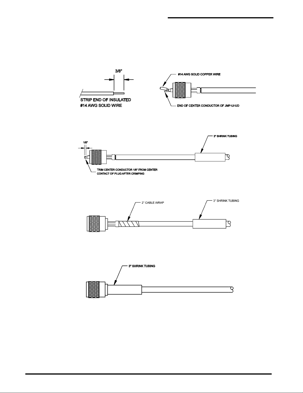
PAL-AT Installation Manual
The procedure for crimping the center conductor requires a short length of #14 AWG solid copper
wire to fill the center contact of the connector. Strip 3/8” of insulation from the wire. Bend the end
of the strands of the center conductor slightly to the side. Next, carefully slide the bare #14 AWG
wire all the way into the center contact as shown. The #14 wire should be inserted next to the
JMP-U conductor and not into the strands of the conductor. Be careful so the strands of JMP-U
do not slide into the connector with the #14 wire. Crimp the center contact as shown using a
0.100" die.
Step F Trim any center conductor (and #14 AWG wire, if applicable) extending out of the center contact
of the plug. Thread the UHF coupling ring onto the UHF plug body.
Step G Place a 2” piece of plastic cable wrap around the cable jacket and slide it under the uncrimped
end of the outer ferrule as far as possible.
Step H Slide the 3” [75 mm] piece of shrink tubing over the crimped outer ferrule until it completely covers
the ferrule. Make sure the shrink tubing does not slide onto the plug body. Heat the shrink tubing
with a heat gun until it has fully shrunk and adhesive oozes out the end. Let the assembly cool
before handling.
Test all connections as described in the “Cable and Connector Testing Procedures” section. Each
end of the cable in the stage shown above will be fastened together by using one UHF straight
adapter. All cable connectors should be encapsulated with non-corrosive RTV sealant and shrink
tubing.
48

PAL-AT Installation Manual
8.2.3 CAJPP Connectors for Jumper Cables JPP and JMP
The CAJPP connector assembly for JPP and JMP jumper cables consists of two crimp style UHF plugs
and one UHF straight adapter. Steps A thru F must be followed to install a connector. It is recommended
to use Ideal Stripmaster® Model 45-091 or 45-092 wire strippers, or equal, for stripping the wires. Use the
die openings for stranded wire for the wire size specified in the steps below.
Step A Measure and cut the required length of cable. The connector components are shown below.
Step B Carefully mark the cable jacket at 3/8”, 3/4” and 1 5/8” from the end.
At the 3/8” mark, strip the wire with the 14 AWG stripping hole. You may need to repeat the strip
with the 16 AWG stripping hole to remove all the core insulation.
At the 3/4” mark, strip the wire with the 12 AWG stripping hole to remove the braid.
At the 1 5/8” mark, strip the wire with the 10 AWG stripping hole to remove the jacket.
Step C JPP only - JPP has foil wrapped under the braid and bonded to the core insulation. Slide the
braid back to the jacket to expose the foil. Use long nose pliers with serrated grip surfaces and
gently squeeze the foil near the end of the core. Gently rotate the pliers back and forth 10° - 30°
several times until the foil breaks free from the core. Unwrap the foil and remove it. This step may
need to be repeated to remove all the foil under the exposed braid.
Step D Slide the UHF plug body over the cable center conductor. Be sure all the strands of the center
conductor slide completely through the center contact of the plug. At the same time, the plastic
core should fit inside the large section of the center contact and the braid should go over the
outside of the inner ferrule. When the cable is inserted properly, 1/16” [1.5 mm] to 1/8” [6 mm] of
the center conductor will extend past the end of the UHF plug body and the plastic core will be
inside the center contact. Caution: Once the crimp tool (PermAlert Part No. 8068300) starts
to close, it must be closed completely before it can be opened again. Crimp the center contact
in the crimp area using a 0.068” die.
49
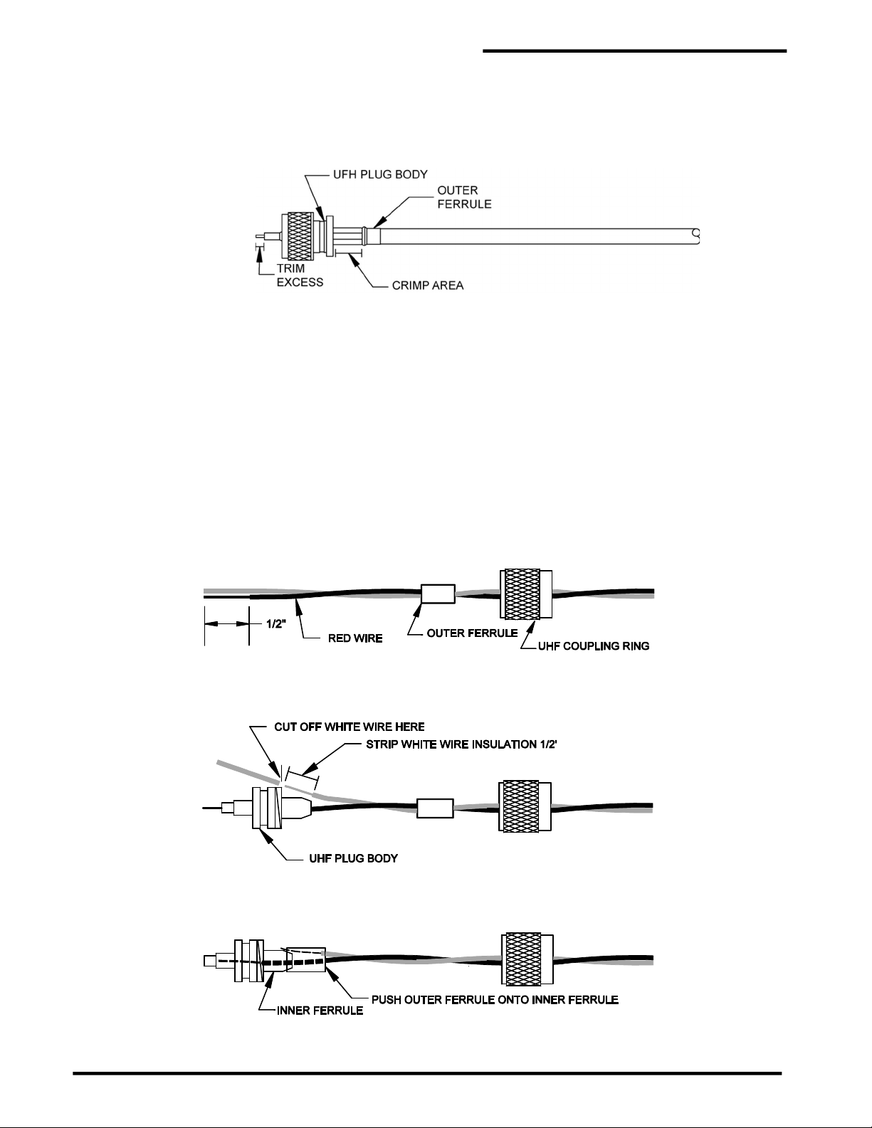
Step E Slide the UHF coupling ring onto the plug. Slide the outer ferrule (and the remaining foil, if any,
for JPP cable) over the braid and up to the UHF plug body. Make sure the braid extends slightly
past the end of the outer ferrule against the UHF plug body. Position the crimp tool 0.255" die
carefully around the outer ferrule. Hold the outer ferrule tight against the plug body and crimp it.
The UHF coupling ring is now captive and cannot be removed from the plug body.
Step F Trim any center conductor extending out of the center contact of the plug.
Test all connections as described in the “Cable and Connector Testing Procedures” section. Each
end of the cable in the stage shown above will be fastened together by using one UHF straight
adapter. All cable connectors should be encapsulated with non-corrosive RTV sealant and shrink
tubing.
8.2.4 CAGOLD Connector for ATP Cable
The CAGOLD cable connector can be used at a calibration point to make it reusable, instead of the
standard permanent crimp connector. Steps A thru G must be followed to install a connector.
PAL-AT Installation Manual
Step A Make sure the red and white wires are twisted with an approximate 2”–3” [50mm-75mm] pitch and
then cut off excess ATP cable. Slide the UHF coupling ring onto the cable, followed by the outer
ferrule.
Step B Remove ½” [12 mm] of the insulation on the red wire.
Step C As a measuring guide, slide the plug body onto the red wire until it stops against the wire insulation.
The wire should extend out of the center contact. Cut the white wire even with the shoulder of the
plug body. Remove the plug body and strip ½” [12 mm] of the insulation from the white wire.
Step D Slide the plug body on the red wire again until the white wire is just past the tapered end of the
inner ferrule. Then slide the outer ferrule over the end of the inner ferrule and the white wire until
it is a snug fit.
50

PAL-AT Installation Manual
Step E Next, take the crimp tool and clamp the 0.255” die around the twisted wires behind the outer
ferrule. Be careful not to pinch the wires. They should slide freely through the die. Then push the
plug body toward the crimp tool to force the outer ferrule and white wire to slide over the inner
ferrule until they are tight against the plug shoulder as shown in the second view.
Step F Use the 0.255” hex die and crimp the outer ferrule.
Step G Bend a short length of #18 AWG [0.75 mm2] solid copper wire to a ¼” [6mm] long right angle and
insert it into the center contact next to the ATP conductor. Insert it as far as the bend.
Straighten the copper wire so it does not interfere with the crimp tool closing. Crimp the center
contact using the crimp tool 0.100” die. Trim excess wire as shown. Slide the coupling ring to the
plug body and thread it onto the body. If there are any gaps between the red and white wires,
twist the connector slightly to remove them.
51
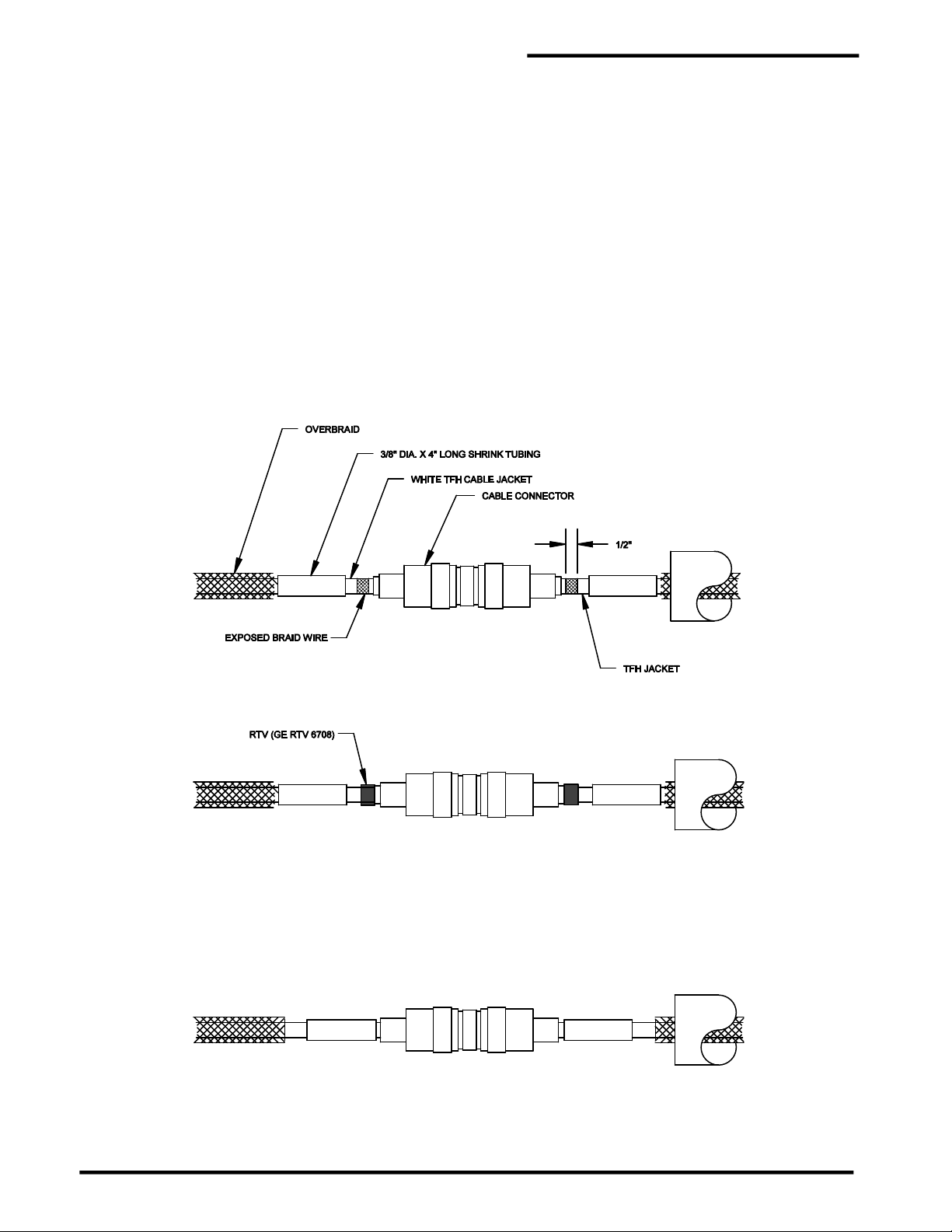
8.3 Shrink Tubing
All cable connectors installed in inaccessible locations or locations subject to frequent leaks or
corrosive environments must be encapsulated with shrink tubing. This applies to sensor cables
and jumper cables. Connectors used for calibration points should not be sealed until the system has
been brought online unless they may be exposed to water before start-up.
8.3.1 Cable Type TFH
1. The TFH cable connector assemblies must be encapsulated in watertight shrink tubing. Test
connectors according to the "Cable and Connector Testing Procedures" before heating the shrink
tubing. Connectors used for calibration points must be kept dry until the system has been
commissioned. After commissioning, the shrink tubing should be installed. If water is allowed
to enter the end of the cable and get under the jacket, the cable must be replaced.
2. Install the shrink tubing in accordance with the following steps:
Step A Slide the overbraid and cable jacket back from the reducing adapter, to expose ½" [12 mm] of
braid wire. Smooth the excess cable jacket away from the connector, so there is at least 5" [125
mm] of smooth surface adjacent to the connector. If the sensor cable is being connected to a
jumper cable, skip steps A and B for jumper cable.
PAL-AT Installation Manual
Step B Place a 1/4" [6 mm] bead of non-corrosive RTV sealant around the cable on the exposed braid
wire.
Step C Slide the 4" [100 mm] long shrink tubing to the reducing adapter, if the CASTD connector is used.
Make sure there are no wrinkles in the cable jacket. Make sure the shrink tubing does not overlap
the reducing adapter. Slide the shrink tubing over the outer crimp ferrule to the back of the
connector body if the CAGOLD crimp style connector is used. Heat the shrink tubing with a heat
gun until it has fully shrunk and adhesive oozes out the end. Do not disturb the assembly until the
shrink tubing has cooled (approximately 5-10 minutes).
52

Step D After both cable ends have been sealed with the 4” [100 mm] shrink tubing, recheck that the
connectors are tightened securely. Test the connector according to the "Cable and Connector
Testing Procedures". Then slide and center the 8" [200 mm] shrink tubing over the connector and
heat it until it is fully shrunk and adhesive oozes out the ends.
Step E Slide the overbraid to the connector and tape in place with electrical tape.
8.3.2 Cable Types AGW-Gold, AGT-Gold and TFH-Gold
Step A Install connectors and test them following the "Cable and Connector Testing Procedures" in this
manual.
Step B Slide a 6" [150 mm] piece of shrink tubing on the cable and tighten the connector assembly
securely.
PAL-AT Installation Manual
Apply a minimum ¼" [6 mm] bead of noncorrosive type RTV completely around the cable next
to the end of each of the connectors.
Step C Center the shrink tubing over the connector. Carefully heat the tubing, slightly, over the center of
the connector. Caution: If the shrink tubing is overheated in the center area, it may tear as
it tries to shrink to the size of the cable. Next heat the remainder of the tubing. Do not heat
the tubing any longer than required to shrink the tubing around the cable.
53

8.3.3 Cable Types JMP-U/-UD, JPP and JMP
Step A Install connectors and test them following the "Cable and Connector Testing Procedures" in this
manual.
Step B Slide a 6" [150 mm] piece of shrink tubing on the cable and tighten the connector assembly
securely.
Apply a minimum ¼" [6 mm] bead of noncorrosive type RTV completely around the cable on
the installed shrink tubing next to the end of each of the connectors.
Step C Center the 6” long shrink tubing over the connector. Carefully heat the tubing, slightly, over the
center of the connector. Caution: If the shrink tubing is overheated in the center area, it may
tear as it tries to shrink to the size of the cable. Next heat the remainder of the tubing. Do
not heat the tubing any longer than required to shrink the tubing around the cable.
PAL-AT Installation Manual
8.4 Cable and Connector Testing Procedures
8.4.1 General
The following tests should be performed on each length of cable after both connectors are installed. Figure
8-1 illustrates the tests. Any overbraid or outer jacket is not shown.
8.4.2 Continuity Test
The continuity test checks for broken cable, open connectors, and poor connections.
1. Connect a short jumper wire with alligator clips between the UHF connector’s center contact and the
body of the connector at one end of the cable, as shown in figure 8-1. Note: Do not clip onto the
threaded coupling ring because the ring is not tightly secured, resulting in intermittent
readings.
2. Connect the ohmmeter's test leads to the connector’s center contact and connector body on the other
end of the cable.
3. The ohmmeter reading should be less than 10 ohms/1000' [10 ohms/300 m] of cable. If it is not, check
the jumper wire, test lead connections, and repeat the test. If the problem persists, contact the
PermAlert Field Service Department for assistance.
54
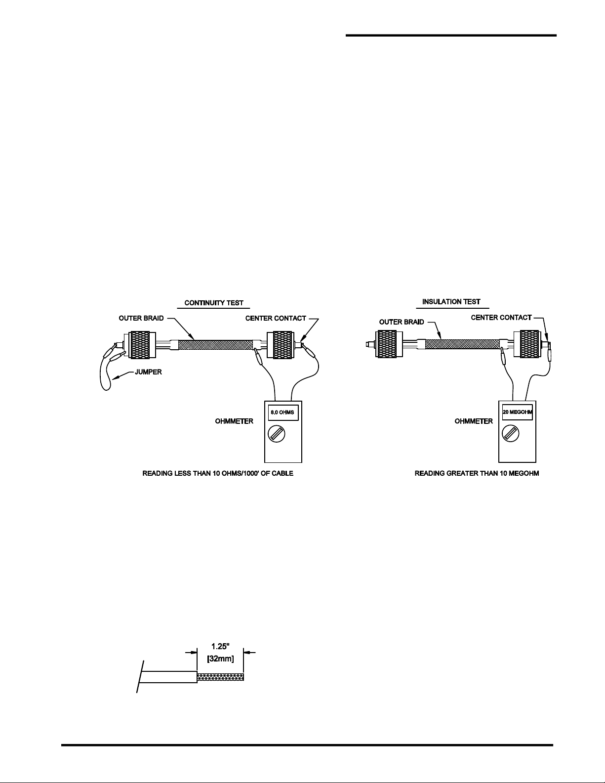
8.4.3 Alternative System Test
1. Connect the entire cable string to the PAL-AT panel.
2. Make sure the panel is turned off. Set the impedance jumper for the cable under test – position C (w/o
ZBA) or D (w/ZBA). If applicable, make sure the replaceable fuse in the ZBP is good.
3. Measure the resistance at the far end of the cable string. Connect one test lead to the center contact
of the last connector and the other lead to the connector body. The resistance should be less than 60
ohms + 10 ohms/1000' [75 ohms/300 m] of cable string.
4. If intermittent connections are suspected, gently flex the connectors while the meter is monitored.
8.4.4 Insulation Test
The insulation test checks for a short between the center conductor and outer braid.
1. Remove the jumper wire used in the continuity test, as shown in figure 8-1 and connect one ohmmeter
test lead to the connector's center contact and the other lead to the connector body.
2. A good cable will give a full-scale reading (at least 10 megohms). Test readings below full scale
indicate damaged cable or an improperly installed connector. If you cannot resolve the problem,
contact PermAlert's Field Service Department for assistance.
PAL-AT Installation Manual
Figure 8-1
Cable Test Procedures
8.5 Cable Connections to Panels
8.5.1 General
The ends of the jumper cables connected to the PAL-AT panel or Zener Barrier Panel need to be
terminated with wire ferrules. The ferrules provide a positive connection and prevent stray strands of the
wires from shorting to adjacent terminals.
8.5.2 Ferrule Installation in PAL-AT Panel
Step A Remove 1.25” [32 mm] of cable jacket
Step B Separate the braid wire into two equal groups. It is easier to unbraid the wire if it is done in ¼”
long increments. It is helpful when working with JMP-U cable to keep tools and fingers damp when
55

PAL-AT Installation Manual
touching the sticky, water-blocking material. Twist each group into a small wire. Remove 1.0” [25
mm] of insulation from the center wire.
Step C JMP-U/-UD Cable
Slide a 14 AWG [2.5 mm²] uninsulated ferrule onto the center wire until it is tight against the center
insulation. Crimp the ferrule using a 2.5 mm² die. Then crimp it again with a 1.5 mm die. Slide a
16 AWG [1.5 mm²] insulated ferrule over each group of braid wire twisted strands. Spread the
ferrules apart to fit into the connector as shown. Align the ferrule ends as shown while minimizing
slack in the braid wire. Crimp the ferrules using a 1.0 mm crimp die.
JMP (from ZBA) or JPP Cable
Slide an 18 AWG (1.0mm²) insulated ferrule onto the center wire until the ferrule insulation is
completely over the wire insulation. Crimp the ferrule using a 0.50 mm crimp die. Slide an 18 AWG
(1.0mm²) insulated ferrule over each group of braid wire twisted strands. Spread the ferrules apart
to fit into the connector as shown. Align the ferrule ends as shown while minimizing slack in the
braid wire. Crimp the ferrules using a 0.50 mm crimp die.
Step D Trim excess wire from the end of the ferrules.
56

PAL-AT Installation Manual
Step E The cable ferrules should be inserted into the cable plug and tightened as shown. Before
connecting the cable, route the excess cable in the enclosure so there will not be
excessive strain or twisting at the terminals. Insert the plug into the appropriate receptacle
as shown. The center conductor ferrule should be in the center terminal of the plug and the two
braid ferrules in the outer terminals. When removing the cable, grip the plug and pull it straight
out of the receptacle. Note the plug and receptacle are polarized so they can only be
connected one way.
8.5.3 Ferrule Installation in Zener Barrier Panel
Step A Remove 1.5” [38 mm] of cable jacket.
Step B Separate the braid wire into two equal groups. Twist each group into a small wire. Remove 1.25”
[32 mm] of insulation from the center wire.
Step C JMP-U/-UD Cable
Slide a 14 AWG [2.5 mm²] uninsulated ferrule onto the center wire until it is tight against the center
insulation. Crimp the ferrule using a 2.5 mm² die. Then crimp it again with a 1.5 mm die. Slide a
16 AWG [1.5 mm²] insulated ferrule over each group of braid wire twisted strands. Align the ferrule
ends as shown while minimizing slack in the braid wire. Crimp the ferrules using a 1.0 mm crimp
die.
57

JPP Cable
Slide an 18 AWG (1.0mm²) insulated ferrule onto the center wire until the ferrule insulation is
completely over the wire insulation. Crimp the ferrule using a 0.50 mm crimp die. Slide an 18 AWG
(1.0mm²) insulated ferrule over each group of braid wire twisted strands. Align the ferrule ends as
shown while minimizing slack in the braid wire. Crimp the ferrules using a 0.50 mm crimp die.
Step D Trim excess wire from the end of the ferrules.
PAL-AT Installation Manual
Step E Before connecting the cable, route the excess cable in the enclosure so there will not be
excessive strain or twisting at the terminals. Insert the center wire into the fuse holder terminal
and tighten the screw. Then insert one of the braid ferrules in the adjacent braid terminal and
fasten it. Repeat with the remaining braid ferrule. If the ferrules were installed properly, there
should be very little slack braid wire.
58
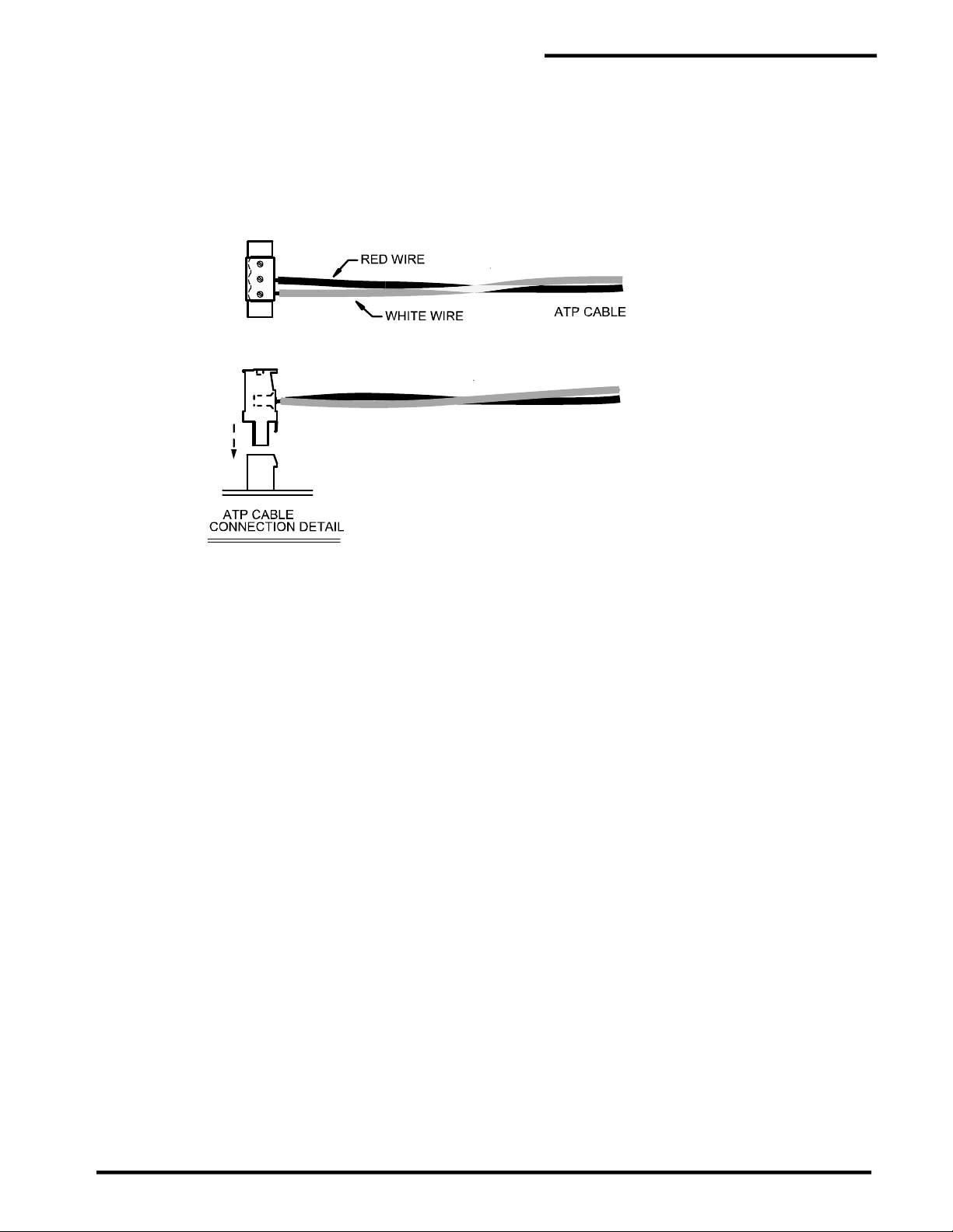
8.5.4 ATP Cable Connection at PAL-AT
The ATP cable uses two of the three cable plug terminals as shown below. Strip 3/8” [10mm] of insulation
from the end of the red and white wires. Insert the red wire into the center terminal and the white wire into
either of the side terminals of the cable plug and tighten as shown. Before connecting the plug, route
the excess cable in the enclosure so there will not be excessive strain or twisting at the terminals.
Insert the plug into the appropriate receptacle as shown. When removing the cable, grip the plug and pull
it straight out of the receptacle. Note the plug and receptacle are polarized so they can only be
connected one way.
PAL-AT Installation Manual
59

9.1 UL Requirements
All PermAlert probes are approved for installation in ordinary, or unclassified, locations. All PermAlert
probes, except the PWS water probe, are also approved for installation in hazardous locations (see
figures 3-2 and 3-3) when the sensing string is connected to a Zener Barrier Panel and Zener Barrier
Assembly.
9.2 Probe Integrator Selection
All probe integrators have a red or blue band(s) of shrink tubing on the probe lead cable. A probe integrator
with a red band(s) is used with PHLR, PSTV, PFS and PTHL probe or a normally closed switch. A probe
integrator with a blue band(s) is used with the PWS probe or a normally open switch.
The number of bands on the probe integrator indicates where it can be used in the sensing string. One
band (-S model) indicates the probe integrator must be connected to the system in the first 5,000' [1500
m] of sensing string. Two bands (-L model) indicate the probe integrator must be connected to the sensing
string beyond 5,000' [1500 m] (Contact factory for specific requirements).
9.3 Probe Installation
1. All PAL-AT probes are furnished with a probe integrator and 60' [18 m] of JMP-U jumper cable in a
NEMA 4X [IP66] junction box. The probe integrator allows the attachment of probes to the PAL-AT
monitoring system. The standard 10" x 8" x 4" [250 mm x 200 mm x 100 mm] junction box can house
one integrator. A 12" x 10" x 4" [300 mm x 250 mm x 100 mm] junction box is recommended if 2 probe
integrators are located in one box.
PAL-AT Installation Manual
9 Probes
2. The maximum temperature for a probe integrator is 180°F [80°C] in ordinary locations. If a probe
integrator is connected to a ZBA in a hazardous location, the maximum temperature is 140°F
[60°C].
3. The standard polyester probe junction box is rated for 150°F [65°C]. An optional high- temperature
fiberglass box is also available. Make sure the enclosure is appropriate for the ambient temperature.
4. Some probe components (epoxy, shrink tubing, etc.) are resistant to many hydrocarbons and
chemicals. However, the probes should be cleaned promptly after a leak event. If left exposed to
hydrocarbon liquids or chemicals for extended periods, the probes may require replacement.
5. Mount the probe integrator junction box at a location close to the point being monitored. PermAlert
supplies probes with 20' [6 m] of twin lead cable. Uncoil the twin lead cable. Do not splice on
additional wire to lengthen the leads. If the probe integrator is located in a manhole or pit, which
may collect and hold water, mount the junction box as high as possible.
6. Figures 9-1 and 9-2 show the recommended installation procedures. Figures 9-3 thru 9-7 show typical
probe installations. Install the probe and use electrical conduit and/or watertight cord grips, as
necessary, to prevent water entry where the probe twin lead penetrates the monitored area. If the
probe lead length is longer than 5' [1.5 m] and the probe is installed in the first 800' [245 m] of a system,
plastic conduit should be used instead of metal conduit. The cord grip (part # 8057950) with the oval
opening in the bushing is used with the twin lead cable. The cord grip (part # 8057954) with the round
hole is for the jumper cable.
7. Once a probe is installed, the twin lead should be routed to the junction box containing the probe
integrator. Trim the excess length of the probe twin lead before splicing it to the probe
integrator. Splice the leads to the integrator by using the crimp connectors supplied with the probe.
Heat the splice with a heat gun to seal the adhesive-lined shrink tubing on the connector.
8. Use all 60' [18 m] of jumper cable furnished with the probe integrator. If the jumper cable leads are
too long, do not shorten, but loosen the watertight cord grips and coil the excess jumper cable within
the probe junction box. One jumper cable length is shorter than the other is. Connect the shorter end
(10') [2.5 m] to the cable segment closest to the PAL-T panel. The longer end of jumper cable (50')
[15 m] should be routed to the connection point for the continuation of the sensing string.
9. Additional jumper cable may be required to be added to the end of a probe installed beyond 3000' [900
m] on the cable string (see table 9-1).
60

PAL-AT Installation Manual
10. If the probe is the end of the sensing string, refer to table 4-1 (section 4) for the required length of
jumper cable needed to be added to the end of the probe.
11. Additional jumper cable may be connected on either side of the probe integrator to facilitate connection
of remote sensing string components.
12. Refer to the "Cable Connector Installation" section of this manual and install a connector on each
length of jumper cable. Test all connectors using the "Cable and Connector Testing Procedures".
13. Cable connections to jumper cable from the probe integrators will become calibration points and must
be accessible during system start-up.
14. The maximum number of probes per cable string is 10. A maximum of three probes installed past
5000' [1500 m] is allowed (Contact factory).
Table 9-1
Additional Jumper Cable after Probe
Probe Location
on Sensing String
ft / [m]
Additional JMP-U/-UD
At End of Probe
ft / [m]
Twin Lead Length Twin Lead Length
20 / [6] 15 / [4.5] 10 / [3] 20 / [6)
Additional JPP
At End of Probe
ft / [m]
15 /
[4.5]
10 / [3]
0-3000 / [0-900] 0 / [0] 0 / [0] 0 / [0] 0 / [0] 0 / [0] 0 / [0]
3001-4000 / [900-1200] 20 / [6] 0 / [0] 0 / [0] 25 / [8] 0 / [0] 0 / [0]
4001-5000 / [1200-1500] 60 / [18] 25 / [8] 20 / [6] 80 / [25] 35 / [11] 25 / [8]
Over 5000 / [over 1500] Contact Factory
Figure 9-1
Typical Probe Connection in Monitored Areas
61

PAL-AT Installation Manual
Typical Conduit Connection Detail
9.4 PHLR Hydrocarbon Probe
The PHLR series is a reusable hydrocarbon probe that detects hydrocarbon liquids in sumps, interstitial
spaces of pipes and any other areas where hydrocarbon liquids can accumulate to a depth of ¼” [6 mm].
The probe is designed to detect fuels (gasoline, diesel fuel, jet fuel, crude oil, etc.) and many hydrocarbon
solvents. The probe is reusable by cleaning or replacing the sensor elements. There are two models of
the PHLR probe available:
The standard PHLR is designed for non-pressurized locations such as sumps, manholes, and non-
pressurized containments. The PHLR can be installed in any orientation – vertical or horizontal.
The PHLR-P is designed for pressurized containment applications. This model is ideal for typical
sealed, containment piping systems that are maintained under pressure with a nitrogen or air blanket.
The PHLR-P should be installed in a vertical orientation. The PHLR-P has vent holes that must not
be submerged in a liquid before the containment is pressurized (see figure 9-4).
An extension to the probe housing can easily be added with standard ¾” Schedule 40 PVC pipe to
accommodate installation requirements.
Figure 9-2
62

(4-7) SCREEN DISKS
PAL-AT Installation Manual
(1) CAP
(1) ACTUATOR
PROBE HOUSING
PROBE
LEADS
Figure 9-3
PHLR Sensor Package
9.4.1 Cleaning Sensor Elements Procedure
The replacement sensor package consists of 10 disks: seven screen disks and three sensor disks as
shown in figure 9-3. The replacement package includes all removable parts: probe cap, sensor elements,
and actuator. Replacement sensor elements can also be purchased separately.
The following procedure is a general guideline to follow to clean the probe and sensor elements after
exposure to hydrocarbon liquids.
Caution: It is the user’s responsibility to determine safety precautions and the suitability of
exposing personnel to the hydrocarbon liquid on the probes and various cleaning solvents
suggested.
(3) SENSOR DISKS
The sensor disks swell after exposure to fuels and solvents. The swelling forces the actuator to move and
operate a low-force sealed switch. Volatile hydrocarbon liquids, such as gasoline, will eventually evaporate
resulting in the sensor disks returning to their original size. This allows the switch to return to the normal
position. A faster resetting process is to disassemble the probe to speed the evaporation of the liquid.
Other liquids, such as diesel fuel and jet fuel that do not evaporate, must be flushed with a solvent to
remove the contamination. Disassemble and clean the probe as follows:
1. Remove excess hydrocarbon contamination from the exterior of the probe.
2. Hold the switch in a vertical position with the cap downward and unscrew the cap. Do this over a table
so the small parts are not lost if they are dropped. Be very careful not to lose the sensor disks.
They are very similar to contact lenses in size and texture.
3. Place the actuator, screens, cap, and sensor disks into a small container of solvent. Coleman Camp
Fuel, which is naphtha, works well and evaporates very quickly. Other solvents that evaporate quickly
and completely are also suitable.
4. Soak the components for a minute or two and then remove them.
5. Let the solvent evaporate until the disks return to the original diameter and fit into the cap easily. If
the sensor disks do not slip easily into the circular holder in the cap, repeat the cleaning process. The
disks should be about 0.5” [12 mm] diameter when dry.
63

6. Reassemble the switch. Carefully alternate the screens and three sensor disks in the cap as shown
in figure 9-3. If there are more than 4 screens, place the extra screens on top. Place the actuator on
top of the top screen. The actuator has a small point in the center of one side that must face the probe
housing as shown. Hold the probe housing vertically and screw the cap finger-tight into the bottom of
the housing.
7. If response time is over 5 minutes for diesel fuel at room temperature, insert the optional fifth screen
next to the actuator. Make sure the extra screen does not activate the probe when it is tightened. If
so, remove the extra screen. The extra screen accommodates manufacturing tolerances and reduces
the amount of swelling of the sensor disks required before the probe activates.
9.4.2 Testing the Probe
The assembled probe can be easily tested with an ohmmeter and a small paperclip.
1. Connect the ohmmeter leads to the probe leads.
2. The reading should be very low, typically under two ohms.
3. Insert the paper clip into one of the five holes in the center of the cap and press gently (1-2 oz of force
[25 g to 50 g]) into the switch.
4. The ohmmeter should read an open circuit or 0.L.
5. Remove the paper clip and the meter should return to the original low reading.
6. Disconnect the ohmmeter.
PAL-AT Installation Manual
9.4.3 Troubleshooting
If the test results are not as expected, the following checks should help determine the problem.
If the original reading is greater than 2 ohms or open, or 0.L, then
o Check the sensor disks and screens are installed correctly. They must be flat, not folded
over.
o Verify the diameter has returned to the original size. Clean again if needed.
o Recalibrate the probe as described below.
If the ohmmeter reading is not an open circuit, 0.L, when the paperclip is inserted, then
o Check the meter leads or probe wires are not shorted together.
o Disassemble the probe and make sure the actuator point is oriented properly to press into
the center of the switch in the probe housing.
o Recalibrate the probe as described below.
9.4.4 Calibrating the Probe
If the sensor elements are replaced, it is necessary to use the correct number of screen elements for
optimum sensitivity (see figure 9-3). The number of screens required varies due to manufacturing
tolerances of the probe. A multimeter is required.
1. Set the multimeter to the ohms function, auto-ranging scale, and connect to the probe leads.
2. Assemble the probe with seven screens and three elements as shown. Tighten the cap finger tight.
3. If the meter reading is less than 2 ohms, the probe fails the calibration. Make sure there are no extra
screen or sensor disks installed.
4. If the reading is 0.L, remove a screen (shown by the dashed arrows in figure 9-3). If the reading is less
than 2 ohms, the calibration is complete.
5. If more than four screens are installed repeat step 4.
6. If the reading is 0.L with four screens, the probe fails the calibration. Make sure there are three sensor
disks and at least four screen disks installed.
If the reading in step 4 is not less than 2 ohms, hold the probe in a vertical orientation and gently tap the
housing. The switch resistance should be less than 2 ohms in the normal dry state.
64

9.5 Typical Installations
Contained Pipe Pressurized Contained Pipe
PAL-AT Installation Manual
Double-Wall Tanks
Typical PHLR and PHLR-P Probe Installations
Contained Area
Figure 9-4
65
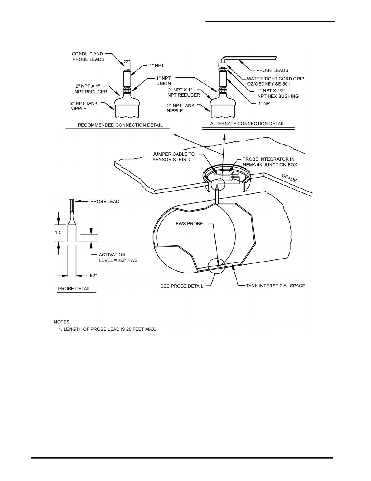
PAL-AT Installation Manual
Figure 9-5
Typical PWS Probe Installation
66
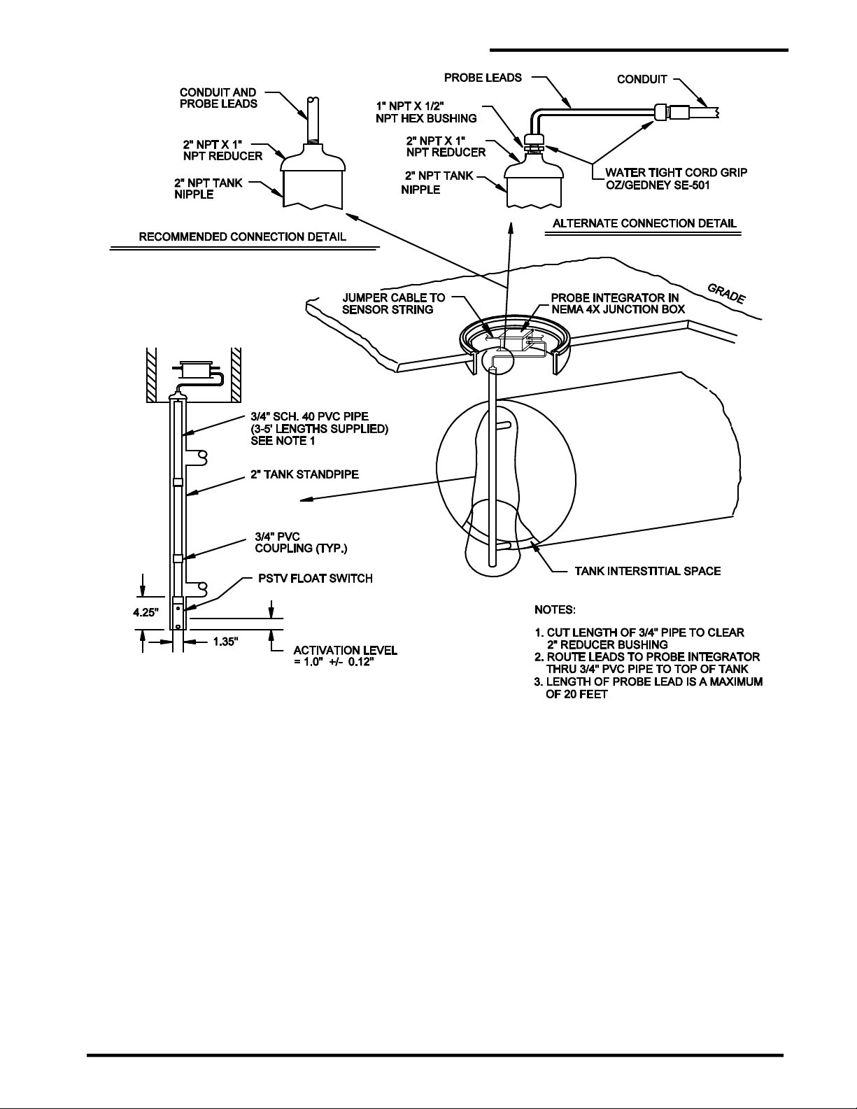
PAL-AT Installation Manual
Figure 9-6
Typical PSTV Tank Float Switch Installation
67

PAL-AT Installation Manual
Figure 9-7
Typical PTHL Installation
68

PAL-AT Installation Manual
Figure 9-8
Typical PFS Installation
69

9.6 Probe Tests
Figure 9-9 shows a typical probe integrator test setup. There are four test procedures based on the type
of integrator used. The red lead of an ohmmeter should be connected to the center pin of either of the
connectors (point A). The black lead should be connected to the connector housing (point B). The
ohmmeter should be set to resistance. Follow the test procedure in figure 9-10 to test the probe integrator
and probes.
PAL-AT Installation Manual
Figure 9-9
Probe Integrator Test Setup
70
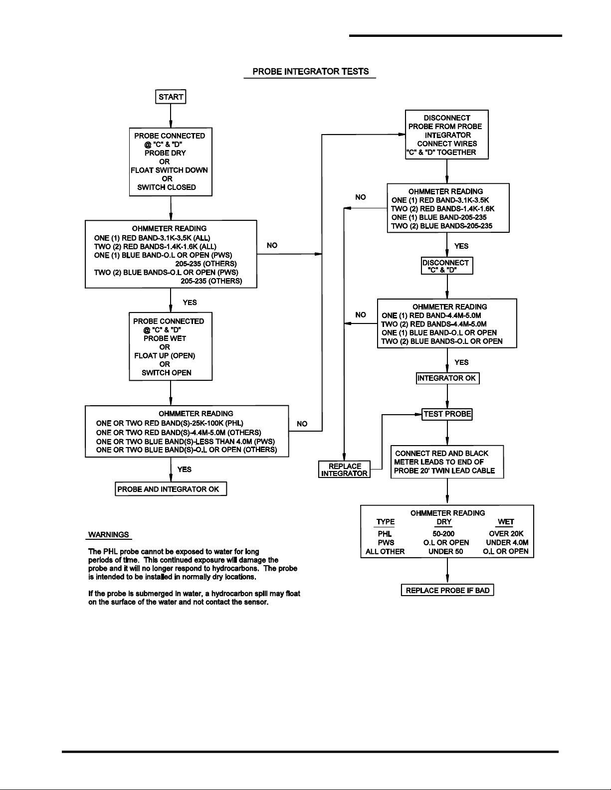
PAL-AT Installation Manual
Figure 9-10
Probe Integrator Test
71

10 ATP Cable in Polyurethane Foam Insulation
10.1 General
This section outlines installation procedures for ATP twisted pair leak detection cable. The cable has two
insulated solid copper wires, one red and the other white. It is installed at the factory in polyurethane foam
insulation.
The cable is typically installed at the 12 o’clock position in the foam insulation for straight runs. It may be
in other orientations for fittings and returns from branch runs, so check the drawing layout for specific job
information. It is very important that the ATP cable be installed straight across each field joint. The
pipe should be rotated so the location where the ATP cable exits the polyurethane foam in adjacent
pipe sections line up to each other. The exit location is stenciled “ATP” on the pipe jacket.
10.2 Pipe Installation Precautions
Extra cable extends past each end of the pipe and is coiled around the pipe to protect it during shipping.
The extra cable must be protected from damage and must be moved away from the pipe before
welding the pipe. Repeated bending of the cable can also damage it.
There are several techniques to protect the ATP cable during the pipe welding/brazing process, depending
on the pipe dimensions and material. The cable can be exposed to temperatures of 300°F [150°C] for a
short time. A wet rag next to the cable can reduce the temperature sufficiently in some cases. If the ATP
cable is within 6” from the weld, additional precautions must be taken. There are heat block insulator
paste products available that can be placed on the pipe between the heat source and the cable. Typically,
the process involves applying a thick layer of insulator paste around the pipe and then removing it after
the welding operation (per manufacturer’s instructions).
PAL-AT Installation Manual
10.3 System Configuration
A PAL-AT Leak Detection and Location System can monitor 1 to 4 cables, or sensing strings, depending
on the model. A sensing string used to monitor ATP must only monitor ATP. No jumper cable,
probes or other types of sensor cables can be connected to the string.
An ATP cable string has at least 50' [15 m] of ATP connected to the panel that replaces the standard
jumper cable. The ATP “jumper” cable connects directly to the ATP cable in the pipe foam insulation at
the start of the pipeline. Watertight electrical conduit should be used to protect the cable and keep it dry.
The watertight requirement for conduit is critical to prevent false alarms.
10.4 Calibration Points
During the initial setup and calibration of the PAL-AT system, connectors at selected locations, called
calibration points, are temporarily disconnected. Therefore, it is imperative to have accessibility to
connectors at calibration points at all times until the system is brought on-line. The cable at these
locations can be prepared for permanent crimp connectors, but the connectors should not be crimped until
the calibration process is completed for each section. A reusable connector (CAGOLD) can be installed
at these points to allow multiple making/breaking the connection if needed (see section 8.2.4).
10.5 ATP Cable and Connector Testing Procedures
The following “Continuity Test” and “Insulation Test with Wet Cloth” should be performed after
each pair of crimp connectors is installed at a field joint, prior to installing the polyurethane foam.
In addition, the continuity test and standard insulation test should be performed again, prior to backfilling
the pipe. When performing connector tests, if a CAGOLD connector is used, the center pin of the UHF
connector is connected to the red wire and the connector housing is connected to the white wire.
A 9-volt digital multimeter, e.g. a Fluke Model 75, can be used for the continuity test and a 500-volt
megger must be used for the insulation test.
72

10.5.1 Continuity Test
The continuity test checks for broken cable, open connectors and poor connections. The test can be
performed on the entire ATP sensor string or a partial section.
1. At the start of the pipe (or at the connector in the panel) temporarily connect the red and white wires
together. A short jumper wire with alligator clips or wire nut can be used. If a UHF connector is
installed, connect the jumper between the UHF connector’s center contact and the body of the
connector, as shown. Note: Do not clip onto the threaded coupling ring because it is not tightly
secured and will give intermittent readings
2. Connect the ohmmeter's test leads to the red and white wires on the other end of the cable.
3. The ohmmeter reading should be less than 6 ohms/1000 ft [20 ohms/1000 m] of cable. If it is not,
check the jumper wire, test lead connections and repeat the test. If the problem still persists, check
the last connector installed and correct the problem.
PAL-AT Installation Manual
ATP Cable Test Procedures
ATP Wet Cloth Test Procedure
10.5.2 Insulation Test
This insulation test checks for a short between the red and white wires or from either wire to the pipe. The
test can be performed on the entire ATP sensor string or a partial section.
The ATP cable must be disconnected from the PAL-AT panel when conducting the
insulation tests or damage to the equipment will result. A 500-volt megger is used to
measure the resistance between the wires and the carrier pipe.
1. If the jumper wire used in the continuity test is still installed, remove it.
2. Perform this test at the unconnected end of the length of ATP.
73

3. Connect one of the megger test leads to the red wire and the other lead to the pipe. The reading
should be “open” or greater than 20 megohms.
4. Check the white wire in a similar manner.
5. Connect one of the megger test leads to the red wire and the other lead to the white wire. The reading
should be “open” or greater than 20 megohms.
6. A good cable will have a reading of at least 20 megohms. If any reading is less than 20 megohms,
check the last connection for a short and repair the problem. The wire insulation may be damaged or
adhesive lined shrink tubing was not installed over a splice and the condition must be corrected.
10.5.3 Insulation Test with Wet Cloth
This insulation test checks for a short between the red and white wires or from either wire to the pipe. This
test should be performed when the ATP splice connections are completed at each field joint, before the
field joint insulation and jacket are installed.
The ATP cable must be disconnected from the PAL-AT panel when conducting the
insulation tests or damage to the equipment will result. A 500-volt megger is used to
measure the resistance between the wires and the carrier pipe. Make sure no one is
touching the wet cloth when the megger test is conducted.
7. If the jumper wire used in the continuity test is still installed, remove it.
8. Perform this test at the unconnected end of the length of ATP just added to the sensor string.
PAL-AT Installation Manual
9. Place a saturated cloth on the splices and exposed ATP cable at the field joint. The water will enter
any damaged wire insulation and cause a low megger reading.
10. Connect one of the megger test leads to the red wire and the other lead to the pipe. The reading
should be “open” or greater than 20 megohms.
11. Check the white wire in a similar manner.
12. Connect one of the megger test leads to the red wire and the other lead to the white wire. The reading
should be “open” or greater than 20 megohms.
13. A good cable will have a reading of at least 20 megohms. If any reading is less than 20 megohms,
check the last connection for a short and repair the problem. The wire insulation may be damaged or
adhesive lined shrink tubing was not installed over a splice and the condition must be corrected.
14. Remove the wet cloth and dry the pipe before insulating the field joint.
10.6 Start of Run
The initial length of ATP cable from the PAL-AT panel is connected to the ATP cable at the start of the
pipe run as shown in figure 10-1.
The ATP cable should be connected to the cable plug in the PAL-AT panel as follows:
Before connecting the cable to the plug, route the excess cable in the enclosure so there will not
be excessive strain or twisting at the terminals. Connect the ATP red wire to the center terminal of the
cable plug. The white wire should be connected to either of the side terminals of the plug. Insert the plug
into the appropriate receptacle as shown. When removing the cable, grip the plug and pull it straight out
of the receptacle. Note the plug and receptacle are polarized so they can only be connected one
way.
74

PAL-AT Installation Manual
10.7 ATP Cable Splices
The ATP cable is spliced at field joints with crimp connectors using the following steps (see figure 10-2).
1. The red wires should be spliced on one side of the pipe joint and the white wires on the other side,
each splice approximately 3"- 4" [75 mm -100 mm] from the end of the pipe.
2. If the ATP cable from the first pipe is not directly in line with the cable from the second pipe, the cable
should be routed in as direct a line as possible between the two splice points (refer to Branch Return
design in figure 10-2).
3. Cut the red wire from one pipe so the end is centered over the first splice location. Cut the other red
wire so the wires meet. Minimize excess slack in the wire.
4. Strip 5/16"-3/8" [7 mm - 9 mm] of insulation from the ends of the red wires. The wire size is 1.5 mm2
(metric size). If the correct stripping tool, Model T60/124, part number 8068309, is not available, use
a tool for #14 AWG. Do not use a smaller die or uncalibrated hand tool, such as wire cutters, that
may damage the conductor.
5. Slide a 1½” [38 mm] long piece of adhesive lined shrink tubing on the wire before crimping
the connector.
6. The crimp tool, Model T60/125, part number 8068308, is ratcheted so the crimp must be completed
once it is started. The crimp connector has an indentation (wire stop) in the center. Two crimps are
required, one on each half of the connector. The model T60/125 crimp tool must be used.
Figure 10-1
ATP Cable Connection - Start of Run
7. Insert one red wire into the connector and place the connector in the T60/125 tool so the die is
centered over the half of the connector with the wire. Make sure the wire is fully inserted into the
connector until it hits the stop, and then crimp the connector.
8. Repeat step 7 with the other red wire.
75

PAL-AT Installation Manual
9. Try to pull the splice apart with 10-25 lb [4.5-11 kg] force to ensure the wires were correctly seated in
the connector.
10. Repeat steps 3-9 for the white wire. The red and white wires must be twisted with a 2” – 3” [50-75
mm] pitch throughout the splice area before crimping the second connector.
11. Slide the 2 pieces of shrink tubing over the splices and shrink the tubing. There should be no copper
wire exposed after the tubing shrinks. If so, the connector should be replaced.
12. There should not be gaps between the red and white twisted wires. If they are not in contact
with each other, twist the wires slightly to eliminate any gap.
13. Test each wire for continuity and insulation as described above.
Figure 10-2
ATP Connection Details
76

10.8 ATP Cable at Tee Connections
Two lengths of ATP cable are used on branch lines and tees (see figures 10-2 and 10-3). Both cables are
typically at the 12 o’clock, position separated 2” - 3” apart. The ATP cable from the preceding section
before a tee is connected to the ATP cable using the procedure described above. At the end of the branch,
the two cables are spliced together as shown.
The return length of ATP cable from the end of the branch is spliced at the tee to the appropriate ATP
cable as shown below using the standard procedure.
An optional second ATP cable may be supplied as a spare or to make all sections available for branch
installation.
PAL-AT Installation Manual
Figure 10-3
ATP Cable at Tee and End of Branch
77

10.9 End of Run Termination
Install a NEMA 4X [IP66] junction box near the end of the pipe. Electrical conduit should be used to protect
the wire if the box is more than a few inches from the pipe end seal. The ATP cable from the pipe should
be spliced to 50 ft [15 m] of ATP cable that is coiled in the junction box (100 ft [30 m] is required if the cable
length is greater than 3300 ft [1000 m]). Make sure the ATP cable remains twisted. The splices to the red
and white wires should be staggered and encapsulated with shrink tubing as described previously.
PAL-AT Installation Manual
Figure 10-4
ATP Cable End of Run Detail
78

PAL-AT Installation Manual
10.10 Requirements for Field Joints with Wind-Down End Seals
This procedure only applies to field joints where two pipes with wind-down end seals are joined together.
It should not be performed until immediately before the insulation and shrink sleeve are applied to
seal the field joint.
1. Drill two 1” diameter holes through the jacket in the wind-down portion of only one of the end
seals. It does not matter which of the two end seals is drilled (see Figure 10-5).
2. The holes should be spaced at least 2” away from the ATP cable to prevent accidental
damage to the cable during drilling.
3. One hole should be located in the top half on the end seal and the other approximately opposite it
in the bottom half.
4. Be careful not to damage the ATP cable or pipe when drilling the holes.
5. Test the ATP wires for continuity and insulation as described above after drilling the holes.
6. Proceed with the normal field joint closing procedure.
Figure 10-5
Wind-Down End Seal Modification
79

Appendix A – Special Instructions
A.1 Supply Power
Supply Power shall be provided by a UL Recognized Power Supply Cat No PS-35-24, manufactured by
Meanwell Enterprises, or a Listed Class 2 Power Supply.
A.2 Control Drawing
Refer to control drawing LD-4901-A0, shown in Figure A-1, for intrinsic safety requirements.
A.3 Zener Barrier Panel (ZBP)
Sensing cable strings that are located in hazardous areas must connect to a Zener Barrier Panel (ZBP),
which is located in an unclassified area. Inside the ZBP is one Zener Barrier Assembly (ZBA) for each
cable sensing string to connect the PAL-AT panel to the ZBP.
The following information for the ZBP is provided for proper connection and installation:
Model ZBP, Part No. 8028115 1 2 3 4
This Leak Detection Equipment (Associated Apparatus) provides intrinsically safe circuits for use
in Class I Division 1 Groups C and D hazardous locations when the unit is installed in accordance
with control drawing (Descriptive System Document) LD-4901-A0.
Maximum input voltage: Um = 250 VAC
WARNING - SUBSTITUTION OF COMPONENTS MAY IMPAIR INTRINSIC SAFETY.
Each zener barrier assembly (ZBA) is assigned the following output parameters:
Uo: 16.02 V dc Co: 1.0 µF
Io: 1.125 A Lo: 56.5 µH
Po 1.248 W Lo/Ro: 31.58 µH/Ω
ATEX/IECEx Certificate number: DEMKO 12 ATEX 1014815X
II (1) G [Ex ia] IIB
IECEx UL 11.0028X
0539 [Ex ia Ga] IIB
Ambient Temperature: -20 °C <= Tamb <= 60 °C
A.4 Probe Integrator
Probe integrators connect probes to the sensing strings. Probes supplied by PermAlert include the probe
integrator. The following information for probe integrators is provided for proper connection and
installation:
Probe Integrators, part numbers 8027629, 8027930, 8027932, 8027934, for use with ZBP.
ATEX/IECEx Certificate number: DEMKO 12 ATEX 1014815X
II 1G Ex ia IIB T4
IECEx UL 11.0028X
0539 Ex ia Ga IIB T4
Ambient Temperature: -20 °C <= Tamb <= 60 °C: Temp Code T4
A.5 Probe Integrator Static Precautions
WARNING FOR HAZARDOUS LOCATIONS - Probe integrators are encapsulated in plastic and present
a possible electrostatic hazard. They are not intended to be cleaned, but if they are, a damp cloth should
be used.
4/30/2012 PAL-AT Special Instructions PPPA-MAN-SAL-001-R00 Eff. Date: 4/30/2012
A-1
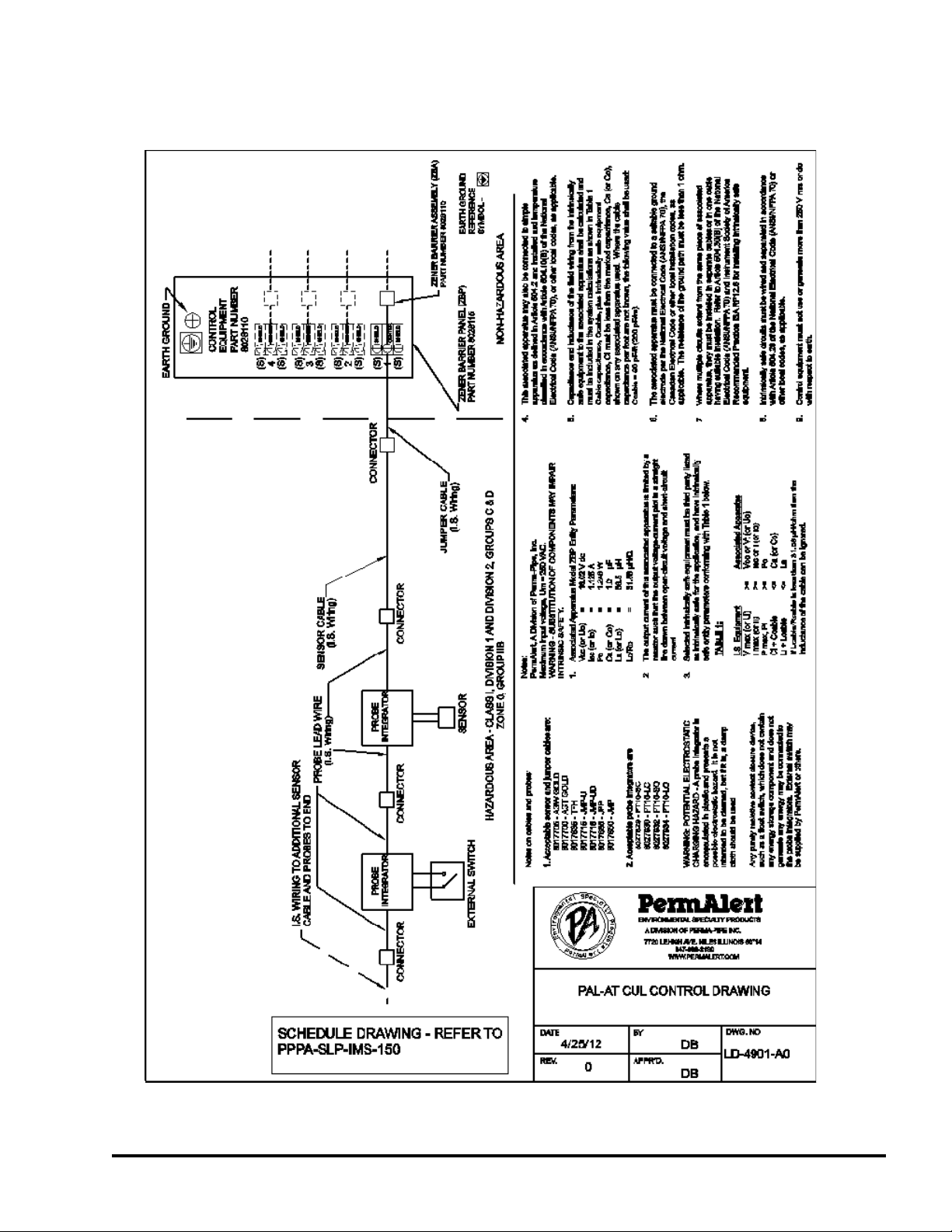
A.6 ZBP Enclosure Fittings
Appropriate fittings, hubs and blanking elements for use on holes on the ZBP enclosure shall contain one
of the following type ratings: 4, 6, 6P, 12, 12K or 13, to maintain the type rating of the selected fitting.
Figure A-1
PAL-AT Control Drawing
4/30/2012 PAL-AT Special Instructions PPPA-MAN-SAL-001-R00 Eff. Date: 4/30/2012
A-2


WARRANTY
Seller warrants that the PermAlert Leak Detection System (the "System") will be free from defects in materials and workmanship
for a period of twelve (12) months from the date of first use of the System or eighteen (18) months from the date of shipment by
Seller to Buyer of the System; whichever is earlier. Seller is not responsible for damage to the System occurring in transit or arising
from the installation, alteration or repair of the System by persons other than Seller's employees, or from any abnormal or improper
use of, negligence with respect to or accident affecting the System. Seller's sole obligation and liability, and Buyer's sole remedy,
under this warranty shall be the repair or replacement, at Seller's election, by Seller of any defective materials or workmanship
covered by this warranty, without the charge to Buyer. Repaired or replacement materials shall be delivered to Buyer f.o.b. Seller's
plant or f.o.b. such other location as Seller shall designate. Seller shall not be responsible for any product returned to Seller without
Seller's prior express consent. Buyer shall be responsible for returning the defective or non-conforming product(s) to Seller at
Buyer’s expense. No claim shall be permitted under the warranty contained herein unless Buyer notifies Seller in writing within ten
(10) days after Buyer first hears of facts giving rise to any such claim and unless notice is given within the warranty period as
provided above. In order to be valid, any notice sent to Seller in connection with said claim under this warranty must reasonably
specify the defect which is the subject of such claim. Buyer shall be responsible for testing and inspecting the System promptly
after receipt and thereafter at such intervals as are reasonably prudent so as to inform Seller of any defects which exist in the
System. Notwithstanding the filing of a claim hereunder, this warranty shall expire after the warranty period in respect to materials
and workmanship which are not then the subject of a proper claim.
To the maximum extent permitted by law, Buyer irrevocably waives all claims against Seller for money damages relating to the
condition, use and performance of the goods sold pursuant hereto, including claims based upon tort, strict liability, negligence and
product liability. Notwithstanding the provisions of the preceding sentence, if money damages are assessed against Seller, in no
event shall Seller's liability for such damages exceed the purchase price of products sold by Seller.
IN NO EVENT, WHETHER BECAUSE OF A BREACH OF WARRANTY OR REPRESENTATION OR ANY OTHER CAUSE,
WHETHER BASED UPON CONTRACT, TORT, WARRANTY OR OTHERWISE, ARISING OUT OF THE PERFORMANCE OR
NON-PERFORMANCE BY SELLER OF ITS OBLIGATIONS UNDER THIS AGREEMENT OR WITH RESPECT TO THE
PRODUCTS SOLD PURSUANT HERETO SHALL SELLER BE LIABLE FOR LOST EARNINGS, INCOME OR PROFITS OR
INDIRECT, INCIDENTAL CONSEQUENTIAL DAMAGES.
THE IMPLIED WARRANTIES OF MERCHANTABILITY AND FITNESS FOR A PARTICULAR PURPOSE AND, EXCEPT AS
SPECIFICALLY SET FORTH HEREIN, ALL OTHER WARRANTIES AND REPRESENTATIONS, EXPRESS OR IMPLIED, ARE
HEREBY DISCLAIMED AND EXCLUDED. NOTHING SHALL BE CONSTRUED AS AN ADDITIONAL WARRANTY UNLESS
SPECIFICALLY DESIGNATED AS SUCH IN WRITING AND SIGNED BY THE SELLER, IN WHICH CASE SUCH ADDITIONAL
WARRANTY SHALL BE SUBJECT TO THE PROVISIONS OF THE APPROPRIATE PARAGRAPHS HEREIN AS TO DURATION
AND LIMITATION OF REMEDY UNLESS SUCH ADDITIONAL WARRANTY EXPRESSLY VARIES SUCH PROVISIONS.
Extended warranty period may be available. Contact PermAlert for more information.

©2019, PERMA-PIPE, Inc. All Rights Reserved. (2/19) PA 2000 REV. 08
 Loading...