

Page 1
INSTALLATION GUIDE
TANDEM® SYSTEM
2015
Page 2

Page 3

TANDEM® SYSTEM
INDEX
SYSTEM DESCRIPTION 4
VENEER UNITS AND STRUCTURAL UNITS ...........4
CAPPING UNIT, STEP UNIT AND STARTER UNIT ......5
TANDEM UNIT ASSEMBLY ......................6
BUILDING A RETAINING WALL 7
STARTER UNIT ..............................7
PRE-ASSEMBLY OF UNITS ......................7
ANCHOR SYSTEM ............................8
TYPICAL CROSS SECTION
AND INSTALLATION PATTERN ...................9
STRAIGHT WALLS ...........................13
CURVED WALLS .............................13
90° CORNER WALL ..........................13
RETAINING WALL CAPPING ....................17
BUILDING A DOUBLE-SIDED WALL 18
DOUBLE-SIDED TANDEM UNIT ASSEMBLY ..........18
STARTER UNIT .............................18
STRAIGHT WALLS ...........................19
CURVED WALLS .............................22
END OF A WALL .............................23
90° CORNER WALL ..........................24
DOUBLE-SIDED WALL CAPPING .................24
BUILDING STAIRS 25
MELVILLE TANDEM STEPS ....................25
LAFITT TANDEM STEPS ......................26
ESPLANADE TANDEM STEPS ...................27
BUILDING PILLARS 28
TANDEM PILLARS WITH PILLAR GRID ............28
TANDEM PILLAR WITH STRUCTURAL UNITS .......36
CONSTRUCTION OF OUTDOOR
LIVING COMPONENTS 40
GENERALITY ...............................40
OUTDOOR GAS FIREPLACE ....................52
OUTDOOR KITCHEN (BBQ, REFRIGERATOR, BAR) ....53
PATIO FURNITURE (BENCH AND TABLE) ..........54
PRIVACY WALLS AND FENCES ..................55
DECK SKIRTING ............................61
TANDEM SYSTEM® – 3
Page 4
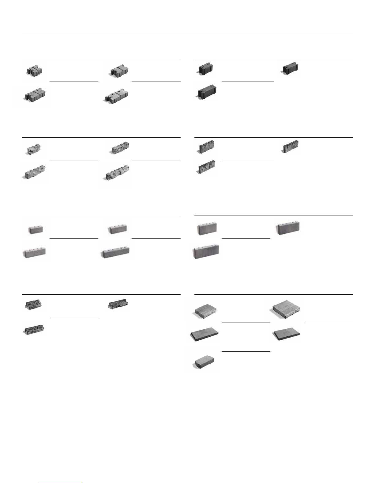
90 mm LAFITT VENEER UNITS
180 mm STRUCTURAL UNITS
180 mm LAFITT VENEER UNITS
90 mm STRUCTURAL UNITS
A – 90 mm VENEER UNIT
90 mm × 67 mm × 201 mm
3 9/16" × 2 5/8" × 7 7/8"
C – 90 mm VENEER UNIT
90 mm × 67 mm × 335mm
3 9/16" × 2 5/8" × 13 3/16"
E – 180 mm STRUCTURAL UNIT
180 mm × 155 mm × 335 mm
7 1/16" × 6 1/8" × 13 3/16"
G – 180 mm STRUCTURAL UNIT
180 mm × 155 mm × 469 mm
7 1/16" × 6 1/8" × 18 1/2"
E – 180 mm VENEER UNIT
180 mm × 67 mm × 335 mm
7 1/16" × 2 5/8" × 13 3/16"
G – 180 mm VENEER UNIT
180 mm × 67 mm × 469 mm
7 1/16" × 2 5/8" × 18 1/2"
A – 90 mm STRUCTURAL UNIT
90 mm × 155 mm × 201 mm
3 9/16" × 6 1/8" × 7 7/ 8"
C – 90 mm STRUCTURAL UNIT
90 mm × 155 mm × 335 mm
3 9/16" × 6 1/8" × 13 3 /16"
B – 90 mm VENEER UNIT
90 mm × 67 mm × 268 mm
3 9/16" × 2 5/8" × 10 1/2"
D – 90 mm VENEER UNIT
90 mm × 67 mm × 402 mm
3 9/16" × 2 5/8" × 15 13/16"
F – 180 mm STRUCTURAL UNIT
180 mm × 155 mm × 402 mm
7 1/16" × 6 1/8" × 15 13/16"
F – 180 mm VENEER UNIT
180 mm × 67 mm × 402 mm
7 1/16" × 2 5/8" × 15 13/16"
B – 90 mm STRUCTURAL UNIT
90 mm × 155 mm × 268 mm
3 9/16" × 6 1/8" × 10 1/2"
D – 90 mm STRUCTURAL UNIT
90 mm × 155 mm × 402 mm
3 9/16" × 6 1/8" × 15 13/16"
180 mm ESPLANADE VENEER UNITS
E – 180 mm VENEER UNIT
180 mm × 60 mm × 350 mm
7 1/16" × 2 3/8" × 13 3 /4"
G – 180 mm VENEER UNIT
180 mm × 60 mm × 562 mm
7 1/16" × 2 3/8" × 22 1/8"
F – 180 mm VENEER UNIT
180 mm × 60 mm × 495 mm
7 1/16" × 2 3/8" × 19 1/2"
DESCRIPTION
LAFITT TANDEM
STRAIGHT CAPPING UNIT
90 mm × 305 mm × 400 mm
3 9/16" × 12" × 15 3/4"
MELVILLE TANDEM
STRAIGHT CAPPING UNIT
60 mm × 305 mm × 600 mm
2 3/8" × 12" × 23 5/8"
STARTER UNIT
90 mm × 200 mm × 40 0 mm
3 9/16" × 7 7/8" × 15 3/4"
LAFITT TANDEM STEP UNIT
90 mm × 400 mm × 400 mm
3 9/16" × 15 3 /4" × 15 3/4 "
MELVILLE TANDEM STEP UNIT
60 mm × 400 mm × 60 0 mm
2 3/8" × 15 3/4" × 23 5/8"
OTHERS UNITS (SOLD SEPARATELY)
4 – TANDEM
®
SYSTEM
90 mm MELVILLE VENEER UNITS
180 mm MELVILLE VENEER UNITS
A – 90 mm VENEER UNIT
90 mm × 67 mm × 201 mm
3 9/16" × 2 5/8" × 7 7/8"
C – 90 mm VENEER UNIT
90 mm × 67 mm × 335 mm
3 9/16" × 2 5/8" × 13 3/16"
E – 180 mm VENEER UNIT
180 mm × 67 mm × 335 mm
7 1/16" × 2 5/8" × 13 3/16"
G – 180 mm VENEER UNIT
180 mm × 67 mm × 469 mm
7 1/16" × 2 5/8" × 18 1/2"
B – 90 mm VENEER UNIT
90 mm × 67 mm × 268 mm
3 9/16" × 2 5/8" × 10 1/2"
D – 90 mm VENEER UNIT
90 mm × 67 mm × 402 mm
3 9/16" × 2 5/8" × 15 13/16"
F – 180 mm VENEER UNIT
180 mm × 67 mm × 402 mm
7 1/16" × 2 5/8" × 15 13/16"
Page 5
DESCRIPTION
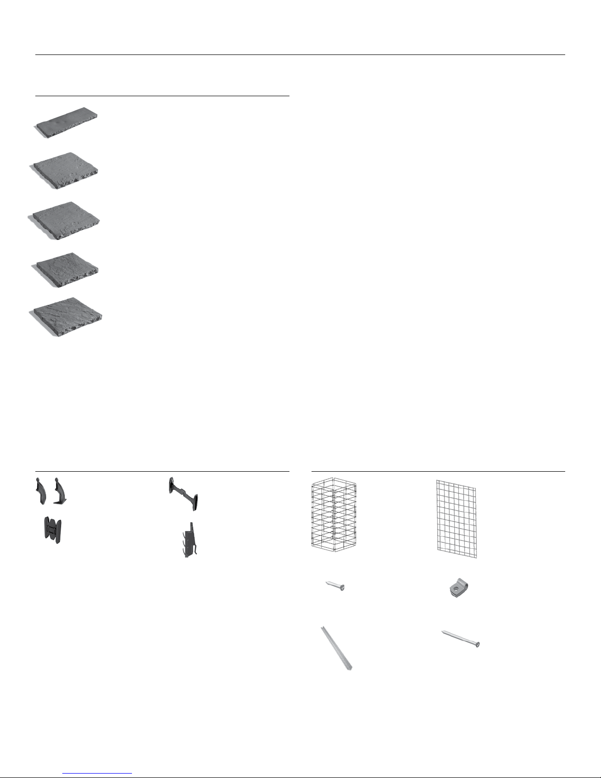
ESPLANADE CHISELED CAPPING UNIT
60 mm × 381 mm × 1067 mm
2 3/8" × 15" × 42"
ESPLANADE PILL AR CAPPING MODULE 25 × 25
60 mm × 635 mm × 635 mm
2 3/8" × 25" × 25"
ESPLANADE PILL AR CAPPING MODULE 27 × 27
60 mm × 686 mm × 686 mm
2 3/8" × 27" × 27"
ESPLANADE PILL AR CAPPING MODULE 29 × 29
75 mm × 737 mm × 737 mm
3" × 29" × 29"
ESPLANADE PILL AR CAPPING MODULE 31 × 31
75 mm × 787 mm × 787 mm
3" × 31" × 31"
SETBACK ANCHOR
CORNER CONNECTOR
TANDEM SHELF ANGLE 8'
64 mm × 64 mm × 2439 mm
2 1/2" × 2 1/2" × 8'
SCREW
#10 × 1 1/4"
SCREW
#10 × 3 1/2"
TAND EM GR ID
CONNECTOR
TANDEM GRID
PILLAR KIT
TANDEM MODULAR GRID
720 mm × 1080 mm
28 3/8" × 42 1/2"
DOUBLE SIDED
CONNECTOR
ANCHORS AND CONNECTORS OTHERS
OTHERS UNITS (SOLD SEPARATELY)
TANDEM SYSTEM
®
– 5
BRACKETS
(LOOP CLAMPS)
Note: Each Tandem Grid Pillar Kit comes with 1 bag of 200 Tandem Grid Connectors.
Each Tandem Modular Grid comes with 1 bag of 60 Tandem Grid Connectors,
10 sc rew s #10
×
1 1/4" and 10 loop clamps.
Page 6
DESCRIPTION
6 – TANDEM® SYSTEM
TANDEM UNIT ASSEMBLY
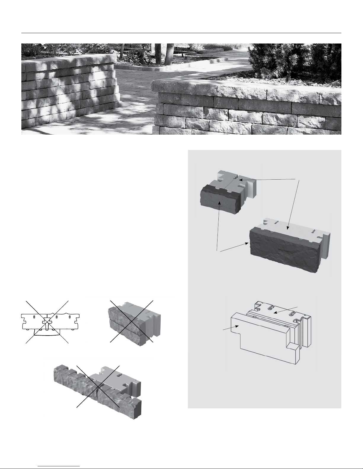
Tandem units come in 2 heights: 90 and 180 mm (3 9/16" and 7 1/16").
For each structural unit, there is a veneer unit of the same length and height.
The unit can be assembled using the dovetail joint (an interlocking male/
female system). Each structural unit has two vertical tenons (male side)
and each veneer unit has at least two mortises (female side). The veneer
units are joined to the structural units by simply sliding the mortises into
the tenons to create the Tandem unit. Today, there are three types of veneer
units; Lafitt, Melville and Esplanade Tandem units. The total depth of the
Lafitt and Melville Tandem unit is 222 mm (8 3/4"); for the Esplanade
Tandem unit, it is 233 mm (9 1/8").
Attention: in general, do not overlap two veneer units on a single
structural unit of the same height, and do not overlap two structural
units on a single veneer unit. Do not install two 90 mm veneer units
on a 180 mm structural unit.
LAFITT TANDEM UNIT
ESPLANADE TANDEM UNIT
Structural unit
Structural unit
La fit t Ta ndem
veneer unit
Esplanade Tandem
veneer unit
Page 7
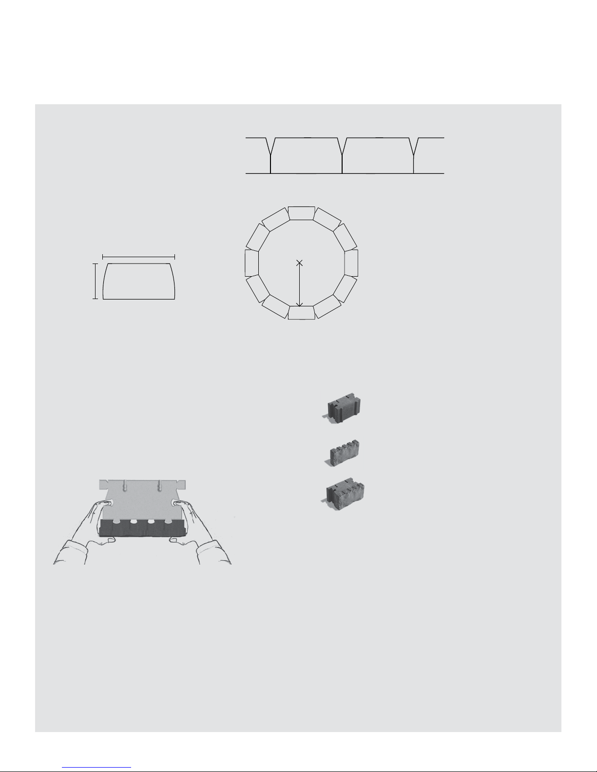
STARTER UNIT
200 mm
400 mm
TANDEM® SYSTEM – 7
R = 36"
STARTER UNIT
The first course of the Tandem wall is built using the Tandem
wall starter unit. This is to be installed directly on the granular
base foundation and levelled. The unit is bevelled to make it
easy to install curved walls.
The use of starter units is strongly recommended given that the
Tandem units (structural and veneer units) can then be placed
on a uniform base ensuring overall wall stability.
CURVED INSTAL LATION
(PLAN VIEW)
STRAIGHT INSTALLATION
(PLAN VIEW)
BUILDING A
RETAINING WALL
PRE-ASSEMBLY OF 90 UNITS
It is best to pre-assemble veneer and structural units before
beginning to stack them in building the wall.
Once pre-assembled, Tandem units are randomly installed on
starter units, using the four different sizes.
PRE-ASSEMBLY OF 180 UNITS
Because the Tandem System 180 components are heavier,
we recommend that you install the structural units first,
then attach their veneer units.
Recommended handling for the Tandem 90 unit
Structural unit
Veneer unit
Tandem unit
Page 8
8 – TANDEM® SYSTEM
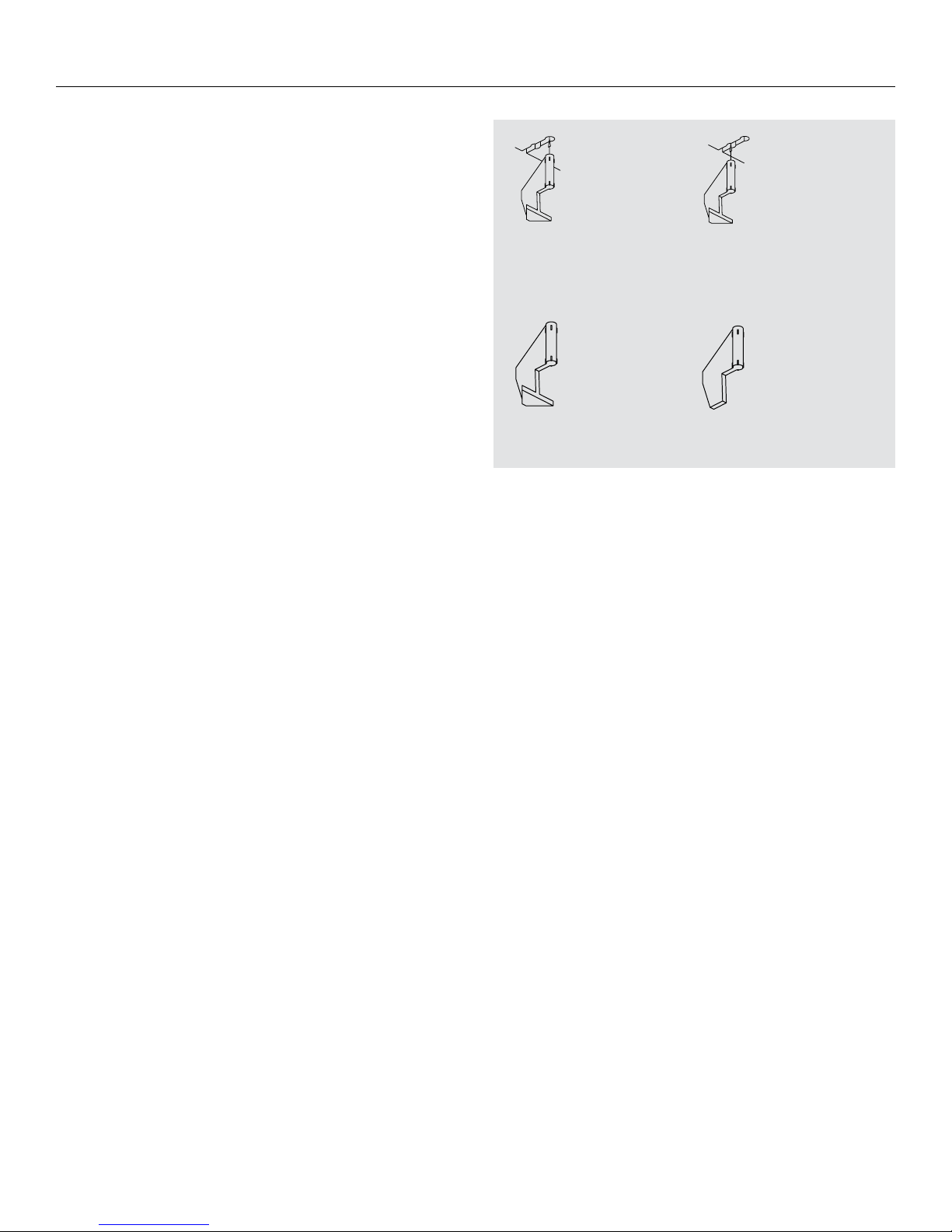
ANCHOR SYSTEM
The way in which the setback anchor is positioned in the Tandem wall
system determines the slope of the wall. This positioning is what allows
for either vertical or sloped walls.
Generally, at least one setback anchor must be installed per
Tandem 90 unit, with two setback anchors for the Tandem 180 unit,
to make sure the wall is stable. Setback anchors come with or without
blades. No-blade setback anchors are used in curved walls. Both types
of anchor can be used in straight walls.
Allowable heights
(1)
: 650 mm (26 in) without a slope (0°, vertical);
1.050 mm (42 in) with a slope of 9°
Note: For a 9° of slope, the setback per row of 90 mm (3 9/16")
is 14 mm (9/16") and the setback per row of 180 mm
is 28 mm (1 1/8")
(1)
Maximum height of the wall including the buried portion of 150 mm (6 in)
without additional load or embankment above the wall.
There are several ways to build a Tandem retaining wall:
Using only Lafitt and Melville Tandem 90 units
Using only Lafitt and Melville Tandem 180 units
Combining Lafitt and Melville Tandem 90 and 180 units in a single wall
Using only Esplanade Tandem 180 units
A typical cross-section and installation pattern are shown
for each type of wall.
BUILDING A RETAINING WALL
Position for building a wall
on a 9° slope.
Maximum height of 1.05 m (42" )
Position for building
a vertical wall.
Maximum height of 0.65 m (26")
Basic
model
Model
without blades
C1 C2
Note: It is possible to use Lafitt and Melville Tandem veneer units in the same wall.
Page 9
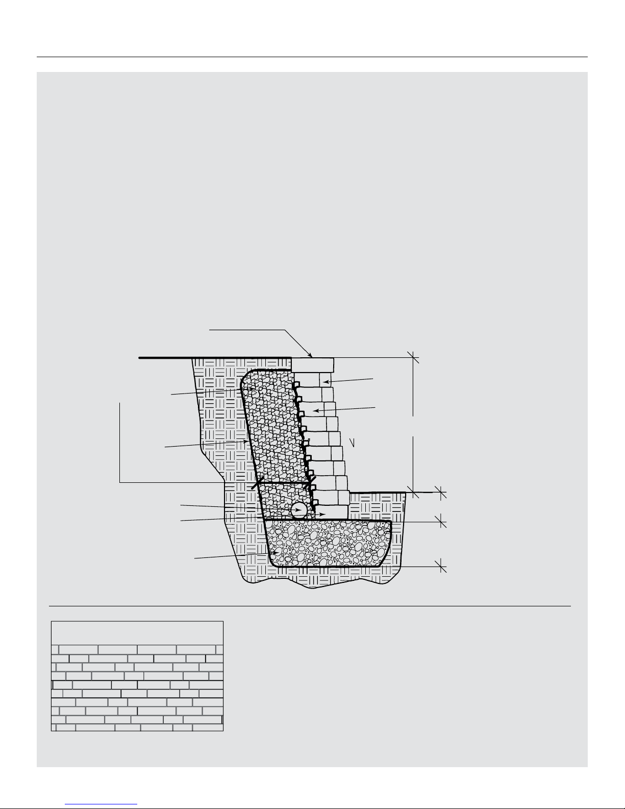
LINEAR PATTERN WITH ONLY LAFITT OR MELVILLE TANDEM 90 UNITS
TANDEM® SYSTEM – 9
BUILDING A RETAINING WALL
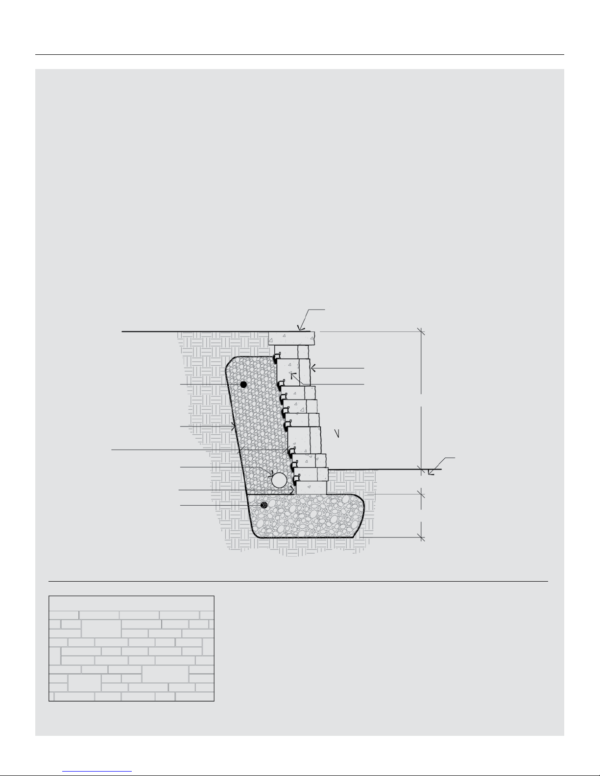
TYPICAL CROSS SECTION AND INSTALLATION PATTERN
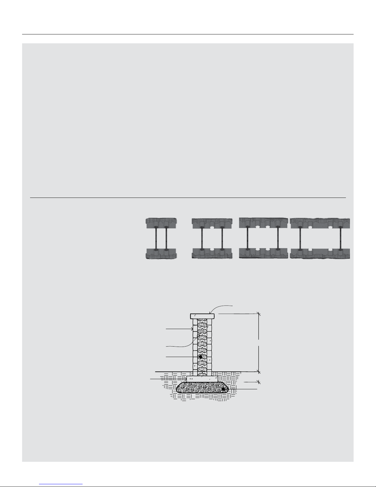
90 mm LAFITT OR MELVILLE TANDEM WALL
A Straight Capping unit
90 mm
×
305 mm × 400 mm
(3 9 /16" × 12" × 15 3/4" )
B Structural units
90 mm
×
155 mm × variable (201, 268, 335 or 402 mm)
3 9/16" × 6 1/8" × var (7 7/8", 10 1/2", 13 3/16", 15 13/16")
C Veneer units
90 mm × 67 mm × variable (201, 268, 335 or 402 mm)
3 9/16" × 2 5/8" × var (7 7/8", 10 1/2", 13 3/16", 15 13/16")
D Perforated drain 100 mm Ø (4 in) connected
E Geotextile membrane
F Granular base 0-20 mm (0-3 /4")
compacted 300 mm (12") min.
G Buried depth 150 mm (6" ) min.
H Clean stone 20 mm (3 /4")
I Starter unit
90 mm × 200 mm × 400 mm
(3 9 /16" × 7 7/8" × 15 3/4")
INSTALLATION PAT TERN
A
D
I
C
B
H
E
F
0° or 9°
300 mm
(12 in) min.
G 150 mm (6 in) min.
900 mm (36 in) max
300 mm (12 in) min.
Page 10
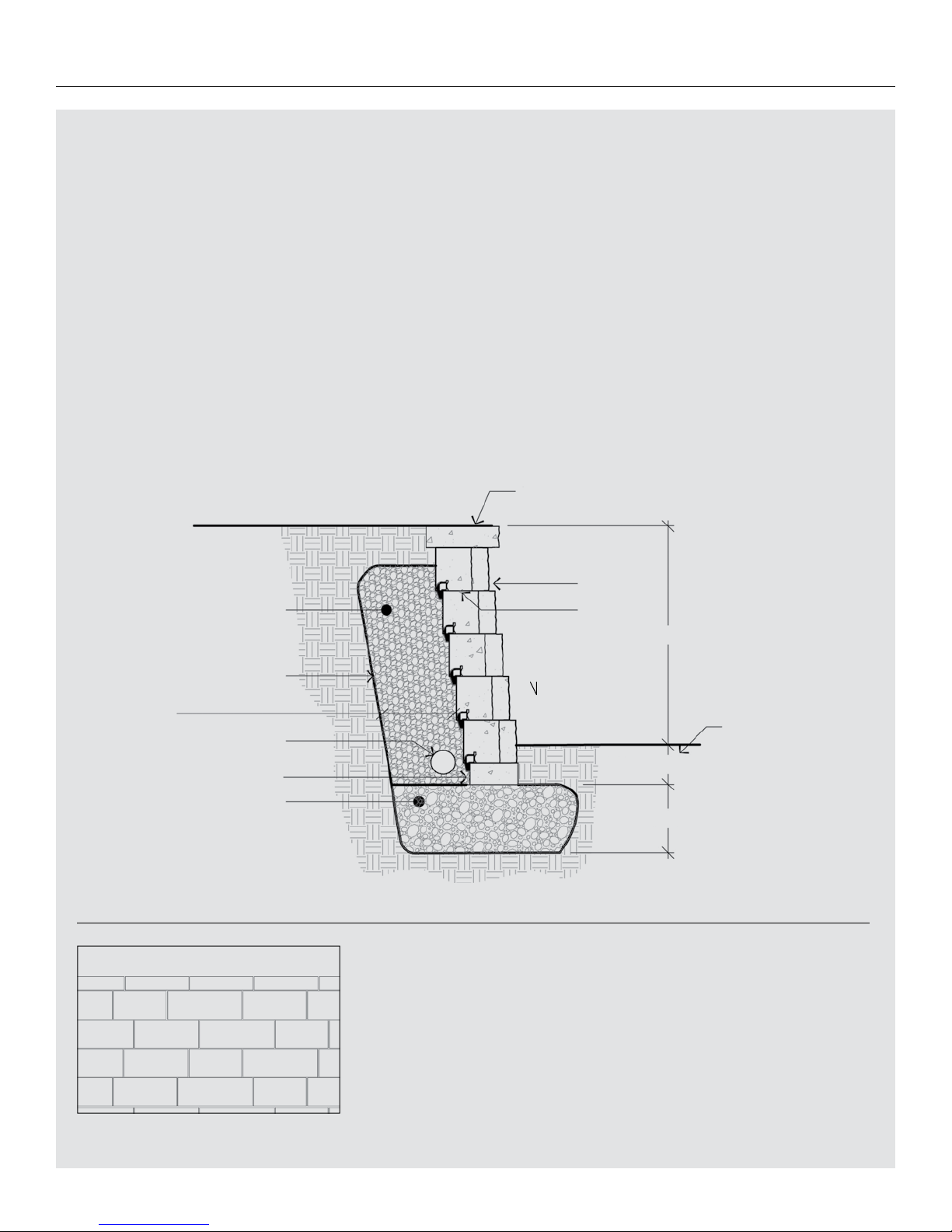
10 – TANDEM® SYSTEM
BUILDING A RETAINING WALL
TYPICAL CROSS-SECTION AND INSTALLATION PATTERN –
LAFITT OR MELVILLE TANDEM 180 WALL
A Straight capping unit
90 mm × 305 mm × 400 mm
(3 9 /16" × 12" × 15 3/4")
B Structural units
180 mm × 155 mm × variable (335, 402, or 469 mm)
7 1/16" × 6 1/8" × var (13 3/16", 15 13/16" or 18 1/2")
C Veneer units
180 mm × 67 mm × variable (335, 402, or 469 mm)
7 1/16" × 2 5/8" × var (13 3/16", 15 13/16" or 18 1/2" )
D 100-mm perforated drain (4") connected to drains
E Geotextile membrane
F 0-20 mm (0-3/4") compacted aggregate base,
min. 300 mm (12")
G Min. buried depth of 150 mm (6" )
H 20 mm (3/4") clean stone
I Starter unit
90 mm × 200 mm × 400 mm
(3 9/16" × 7 7/8" × 15 3/4")
INSTALLATION PAT TERN
LINEAR PATTERN WITH L AFITT OR MELVILLE TANDEM 180 UNITS ONLY
A
B
H
E
D
G
I
F
C
300 mm
(12 in) min.
150 mm (6 in) min.
900 mm (36 in) max
300 mm (12 in) min.
0° or 9°
Page 11
TANDEM® SYSTEM – 11
BUILDING A RETAINING WALL
TYPICAL CROSS-SECTION AND INSTALLATION PATTERN –
WALL WITH MIX OF LAFITT OR MELVILLE TANDEM 90 AND 180 UNITS
A Straight capping unit (connected to drains)
90 mm × 305 mm × 400 mm
(3 9/16" × 12" × 15 3/4")
B Structural units
90 mm or 180 mm × 155 mm × variable
(3 9/16" or 7 1/16" × 6 1/8" × variable)
C Veneer units
90 mm or 180 mm × 67 mm × variable
(3 9/16" or 7 1/16" × 2 5/8" × variable)
D 100-mm perforated drain (4") connected to drains
E Geotextile membrane
F 0-20 mm (0-3/4") compacted aggregate base
G Min. buried depth of 150 mm (6" )
H 20 mm (3/4") clean stone
I Starter unit
90 mm × 200 mm × 400 mm
(3 9/16" × 7 7/8" × 15 3/4")
INSTALLATION PAT TERN
MODULAR PATTERN: 75% TANDEM 90 UNITS
25% TANDEM 180 UNITS
A
D
I
C
BH
E
F
G
0° or 9°
300 mm
(12") min.
150 mm (6") min.
900 mm (36") max
300 mm (12") min.
Page 12
FFG
GF
FE
GE
GG
FE
G
E
A
B
C
D
E
F
G
H
I
12 – TANDEM® SYSTEM
BUILDING A RETAINING WALL
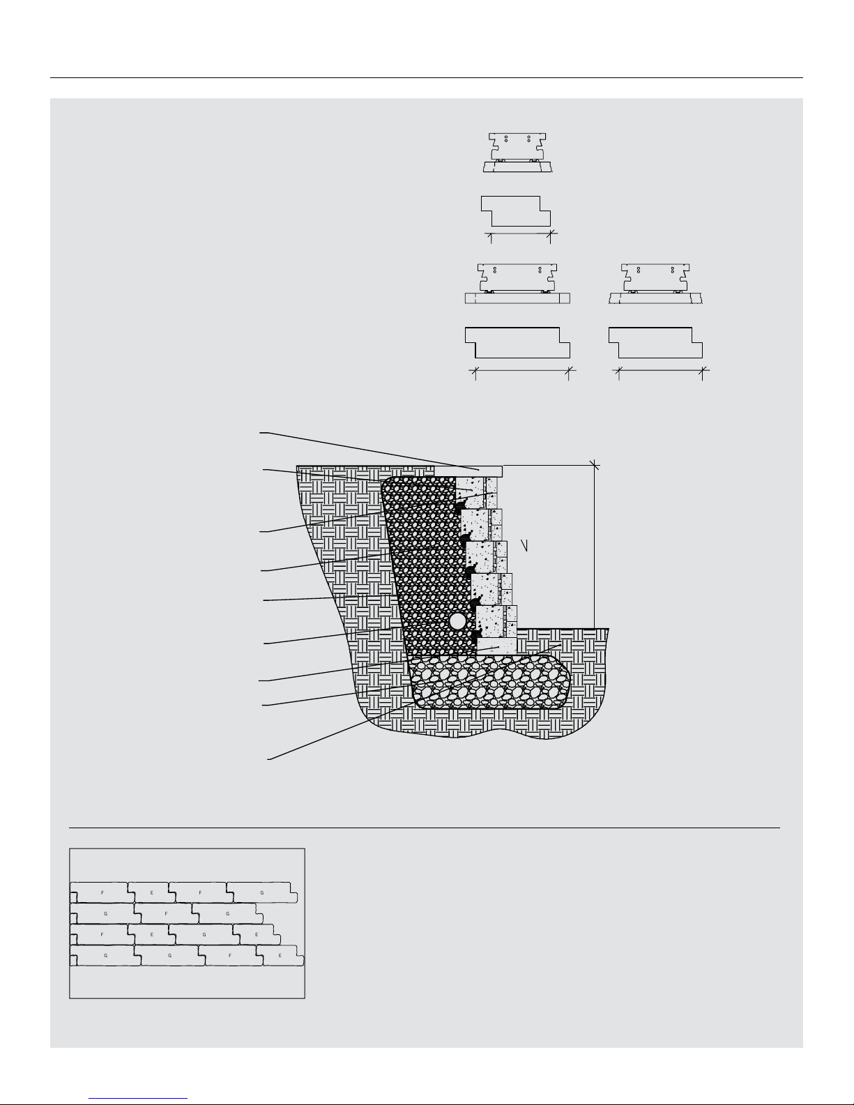
TYPICAL CROSS-SECTION AND INSTALLATION
PATTERN – ESPLANADE TANDEM WALL
A Esplanade chiseled capping unit
60 mm × 381 mm × 1 067 mm
(2 3/8" × 15" × 42")
B Structural units
180 mm × 155 mm × variable (335, 402, 469 mm)
7 1/16" × 6 1/8" × variable (13 3/16", 15 13/16", 18 1/2")
C Veneer units
180 mm × 60 mm × variable (350, 495, 562 mm)
7 1/16" × 2 5/8" × variable (13 3/4", 19 1/2", 22 1/8")
D 20 mm (3/4") clean stone
E Geotextile membrane
F 100 mm (4") perforated drain connected to drains
G Starter unit 90 × 200 × 400 mm (3 9/16" × 7 7/8" × 15 3/4")
H 0-20 mm (0-3/4") compacted granular base, min. 300 mm (12")
I Minimum buried depth 150 mm (6")
INSTALLATION PAT TERN
LINEAR PATTERN WITH ESPLANADE
TANDEM 180 UNITS ONLY
E
E
G F
G F
562 mm
(22 1/8")
495 mm
(19 1/ 2")
350 mm
(13 3/ 4")
0° or 9°
900 mm
(36") max
Page 13
C B A D
F EG
LAFITT TANDEM – 90 mm UNITS LAFITT TANDEM – 180 mm UNITS
TANDEM® SYSTEM – 13
BUILDING A RETAINING WALL
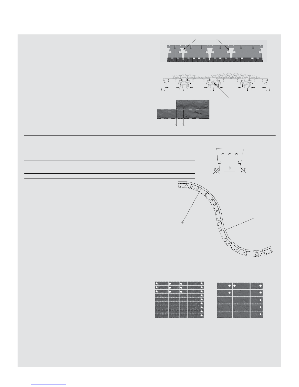
CURVED WALLS
Using some Tandem units yields the minimum following cur ves:
Curved sections of walls must generally be built
using the smallest units.
For a curved Lafitt Tandem 90 wall, use units A, B and C.
For Lafitt Tandem 180 and Esplanade Tandem walls,
units E and F must be used. Their ends are bevelled
to make it easier to install the curved wall.
Since Melville Tandem veneers all have a tex tured side,
the minimum bend radius is greater.
Remember that there will be a surplus of longer units for
the remainder of the wall. In building convex curves (outer curve),
the wings of structural units may have to be cut off.
STRAIGHT WALLS
To build straight Tandem walls, install the units randomly, using equal numbers of all
unit sizes according to the typical cross-section and installation pattern associated
with each type of walls.
To combine the Tandem 90 and 180 units in a single wall, just use units of each
height randomly, in a proportion that creates an aesthetically pleasing result. We
recommend the following proportions: 75% Tandem 90 and 25% Tandem 180
(in terms of wall surface).
Note that the Esplanade Tandem system requires 17% fewer structural units
than veneer units. 1 cube of 60 structural units = 4.32m2 (46.52 sq. ft)
1 cube of 60 veneer units = 5.06m
2
(54.52 sq. ft)
When building a Tandem wall, avoid aligning vertical joints between rows as much
as possible. Allow a minimum overlap of about 67 mm (2 3/4") between modules to
make sure the vertical joints do not line up. (See Installation pattern)
90° CORNER WALL
When building a retaining wall, it is best to start with a corner to avoid breaks
and alignment of vertical joints. Specially designed veneer units are needed
to build a 90º corner. These units have a textured end.
LAFITT TANDEM
A Lafitt Tandem 90 cube contains 18 textured end veneer units per row.
To form the corner, use B, C or D veneer units.
A Lafitt Tandem 180 cube contains 8 textured end veneer units per row.
All of the veneer units (E, F and G) can be used to build the corner.
MELVILLE TANDEM
All of Melville Tandem veneers have one textured side.
ESPLANADE TANDEM
Both ends of all Esplanade Tandem veneer units are textured,
use only F & G capping to create 90° angles.
LAFITT
TANDEM 90
LAFITT
TANDEM 180
MELVILLE
TANDEM 90
MELVILLE
TANDEM 180
ESPLANADE
TANDEM 180
Convex curves (outside) 1.5 m (5 ft) 1.5 m (5 ft) 1.8 m (6 ft) 2.4 m (8 ft) 1.5 m (5 ft)
Concave curves (inside) 1.2 m (4 ft) 1.5 m (5 ft) 1.8 m (6 ft) 2.4 m (8 ft) 1.2 m (4 ft)
67 mm min.
(2 3/4")
Fill the empty space with
20 mm (3/4") clean stone
LAFITT TANDEM WALL
(PLAN VIEW)
ESPLANADE TANDEM WALL
(PLAN VIEW)
STACKING POSITION ON PALLETS (WITH A TE XTURED END)
Empty space
Cut off the extremeties
(wings) if nece ssary
R = 1.5 m
(5 ft)
R = 1.2 or 1.5 m
(4 or 5 ft)
Page 14
14 – TANDEM® SYSTEM
BUILDING A RETAINING WALL
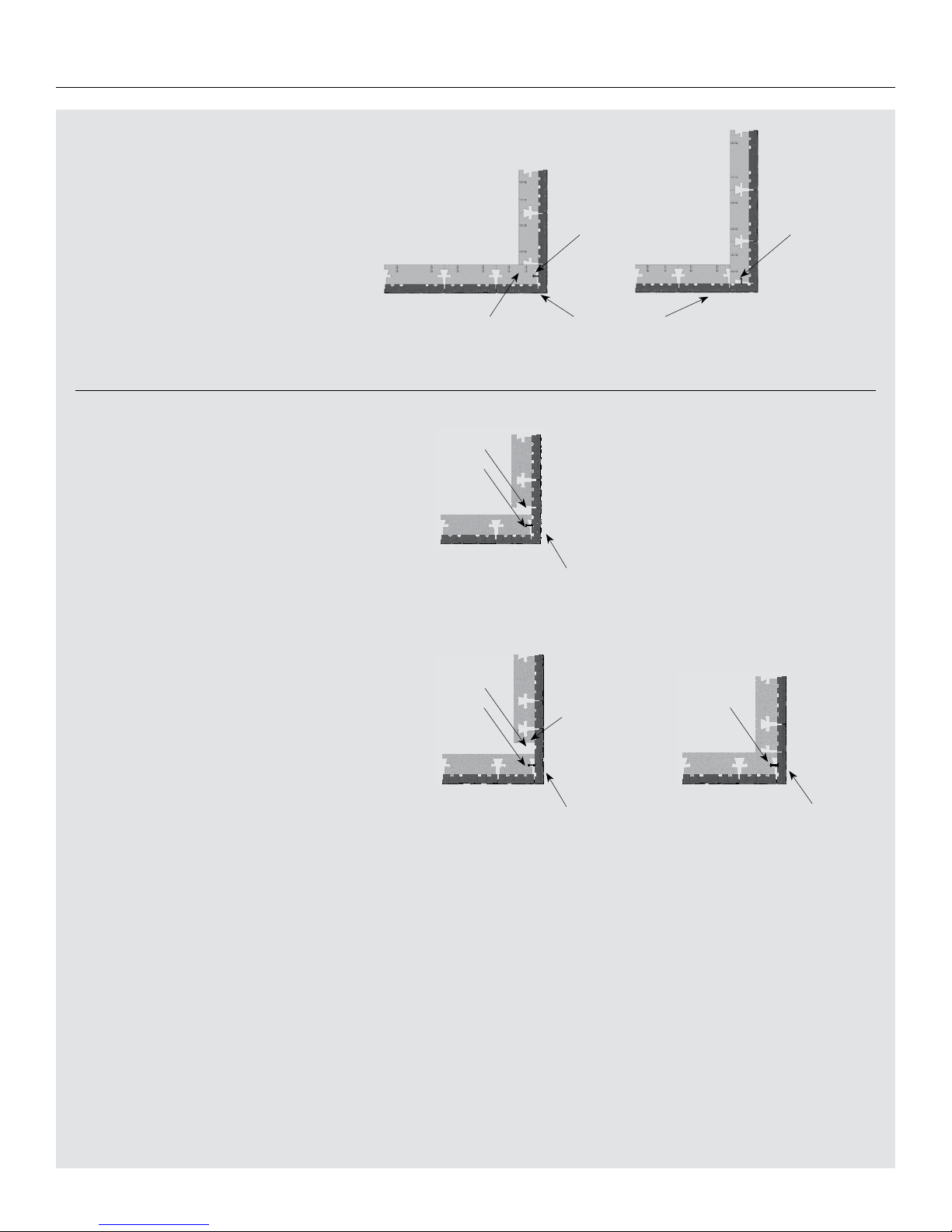
OUTER CORNER –
LAFITT OR MELVILLE TANDEM WALL
PRINCIPLES
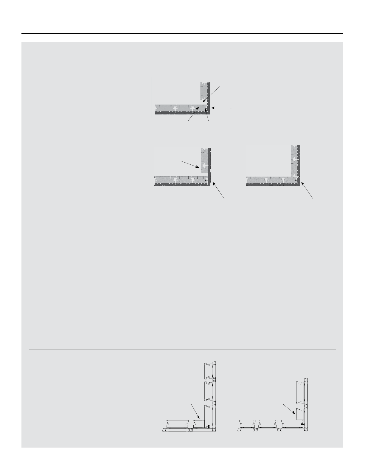
An outer corner is created using veneer units with the textured
end out.
These units are reversible to form both left and right corners.
For each course, the veneer that forms the corner is affixed
to the structural unit using corner connectors designed
specifically for this purpose. It is simply of question of
alternating the placement of units from one course to the next.
We recommend adhering the elements used to make the corner
of each row using Permapro concrete adhesive.
OUTER CORNER DETAIL –
90 mm LAFITT OR MELVILLE TANDEM WALL
There are three ways of building a corner:
Option 1
Use corner veneer unit with a textured end B uncut, and begin
the wall perpendicularly leaving an empty space that will be
backfilled with clean stone
Option 2
Use corner veneer unit with a textured end C or D, uncut,
attached to structural unit A cut in half.
Option 3
Use corner veneer unit with a textured end B, C or D, cut at
222 mm (8 3/4") and begin the wall perpendicularly, pressing it
up against the existing wall. Gently hammer the freshly cut side
to obtain a similar finish as the other sides.
1ST ROW
OPTION 1
OPTION 2 OPTION 3
2ND ROW
Corner connector
Corner connector
Corner connector Corner connector
Backfilled with clean stone
Backfilled with clean stone
Veneer unit B, C or D
cut at 222 mm
Corner connector
Structural unit Veneer unit with textured end
Veneer unit C and D
with a textured end, uncut
Veneer unit B
with textured end
Structural unit A
cut in half
Page 15
TANDEM® SYSTEM – 15
BUILDING A RETAINING WALL
90° OUTER CORNER DETAIL
180 mm LAFITT OR MELVILLE TANDEM
There are three ways to build an outer corner using
Lafitt or Melville Tandem 180 units:
Option 1
Use an uncut textured end veneer unit E and start the wall
perpendicularly, leaving an empty space that will be backfilled
with clean stone.
Option 2
Use an uncut textured end veneer unit F or G attached to a
structural unit E, cut in half. The empty space is back filled with
clean stone.
Option 3
Use a textured end veneer unit E, F or G cut at 222 mm, and
start the wall perpendicularly, simply pressing it up against the
existing wall. Gently hammer the freshly cut side to make the
finish similar to the other sides.
90° OUTER CORNER DETAIL
MIX OF LAFITT OR MELVILLE TANDEM 90 AND 180
To build a corner for a wall featuring a mix of Tandem 90
and 180 units, for each given row height, use corner units
of the same height ( Tandem unit with associated corner veneer).
Corners are built using the options available for that height
(90 or 180), as illustrated and explained earlier in this document.
This principle applies to both outer and inner corners.
The choice of corner unit heights is a matter of aesthetics.
The 90 and 180 units must be inserted in a similar proportion
to the remainder of the wall.
OPTION 1
OPTION 2 OPTION 3
Backfilled with 20 mm clean stone
Structural unit E
cut in half
Textured end veneer unit E,
F or G cut at 222 mm
Structural unit Corner connector
Textured end veneer
unit F or G uncut
90° OUTER CORNER DETAIL
ESPLANADE TANDEM
Build an outer corner by simply overlapping the ends of the
veneer units. The corner is formed by installing a veneer F
or G unit on the end of the last Tandem unit, and inserting a
corner connector to join the two components and strengthen
the corner. Then, cut a structural unit and install it behind the
previously attached veneer.
1ST ROW 2ND ROW
Structural unit cut in half Structural unit cut in half
Veneer unit E
uncut
BUILDING A RETAINING WALL
Page 16
16 – TANDEM® SYSTEM
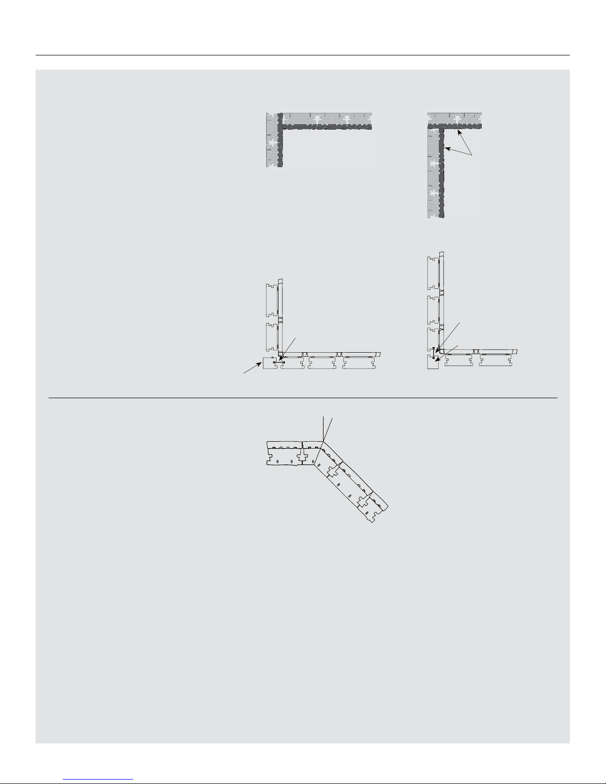
OPTION FOR ESPLANADE TANDEM
For the Esplanade Tandem wall, we recommend using units F
and G for the inner corners. Use half a structural unit to fill
the space created in installing the inner corner. It will support
the cap and will be attached to the adjacent structural unit
using a double-sided connector. (See the following illustration.)
BUILDING A RETAINING WALL
INNER CORNER
Build a Lafitt, Melville or Esplanade Tandem inner corner
according to the principle shown here, using Tandem 90
units C or D and 180 units E, F or G.
45° CORNER
It is also possible to build corners on a 45° angle. Simply cut
each Tandem unit used to make the corner on a 22.5° angle.
These Tandem units must be adhered together using Permapro
concrete adhesive on the horizontal and vertical sides.
INNER CORNER, PRINCIPLES
TANDEM CUT AT AN ANGLE
22.5°
1ST ROW 2ND ROW
Tandem 90 units C or D
and 180 units E, F or G
Double-sided
connector
Cut the structural
unit in equal halves
Double-sided
connector
Second half of the
structural unit
Page 17
TANDEM® SYSTEM – 17
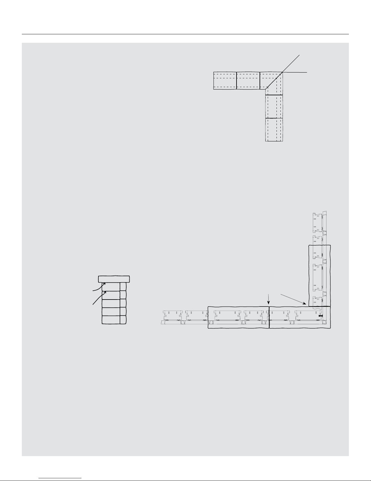
45°
BUILDING A RETAINING WALL
RETAINING WALL CAPPING
The Lafitt Tandem retaining wall is completed using Lafitt Tandem capping
units (90 × 305 × 400 mm). The Melville Tandem wall is finished with the use
of the Melville Tandem Capping units (60 mm × 305 mm × 600 mm). To cap a
wall with a 90° corner, capping units must be cut at a 45° angle.
Lafitt or Melville Tandem capping units are also used to cap curved walls.
The units must be bevelled on site to match the final shape of the wall.
Options: Straight and bevelled capping units from the Celtik wall system and
the Esplanade chiseled capping units can also be used to highlight the wall’s
finish (different colours and texture s).
Esplanade Tandem retaining walls are capped by placing the Esplanade
chiseled capping units (60 × 381 × 1067 mm or 2 3/8" × 15" × 42"). To cap a
90° corner, simply install two capping units at a 90° angle. Note that one out
of two Esplanade chiseled capping units is textured on 3 sides (2 sides and
one end). For cur ved walls, capping units must be bevelled on site to match the
final shape of the wall.
Options: Straight and bevelled Celtik wall system capping units
and Lafitt or Melville Tandem capping units can also be used.
Note that all capping units must be glued to the last row of Tandem units using
Permapro concrete adhesive.
If necessary, level the second last course with stone screening. Make sure
the surface is clean, so that the capping can be glued to the top course with
Permapro concrete adhesive.
Glue the capping units
to the last row.
Level with stone
screening
if required.
ESPLANADE RETAINING WALL CAPPING
For a better finish, grind
the ends if needed.
Page 18
18 – TANDEM® SYSTEM
BUILDING A DOUBLE-SIDED WALL
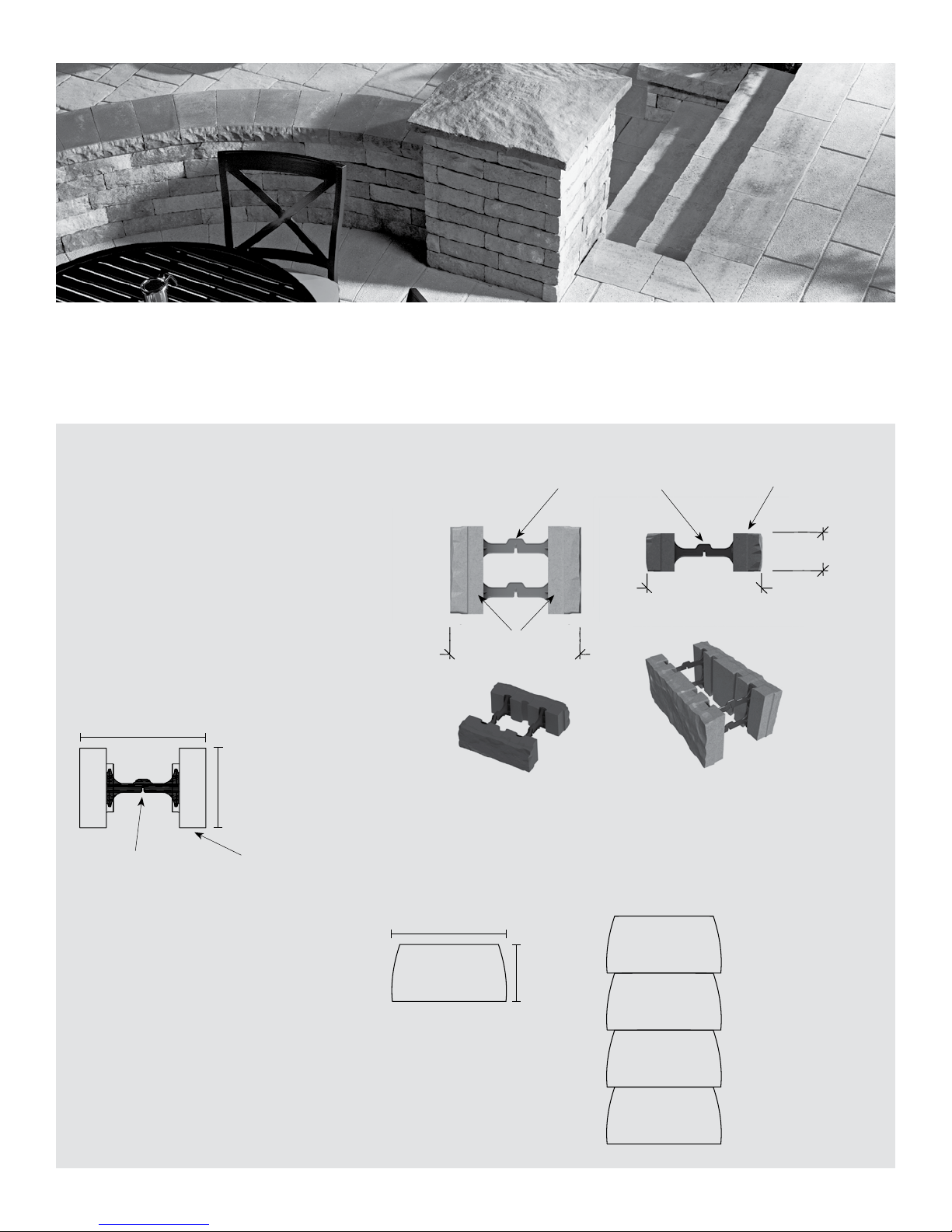
DOUBLE-SIDED TANDEM UNIT ASSEMBLY
Installing a double-sided wall requires the use of two veneer units held together
using connectors. Connectors are inserted into the mortises on the veneer units
thus connecting them two by two in order to create the double-sided Tandem unit.
The work is complete once 20 mm (3/4 in) clean stone is placed between the
veneers of every other course, and the capping unit is installed. Lafitt and Melville
Tandem 90 and 180 veneer units, as well as Esplanade units can be used to build
straight or cur ved double-sided walls, as well as 90° corners.
Allowable heights
The Tandem wall system can be used to build a double-sided wall
with a maximum above-ground height of 711 mm (28 in). The wall is built
completely vertical without a slope.
DOUBLE-SIDED LAFITT
TANDEM MODULES
DOUBLE-SIDED ESPLANADE TANDEM MODULE
DOUBLE-SIDED TANDEM UNIT ASSEMBLY
268 mm (10 9/16 in)
90 mm (3 9/16 in)
Veneer unit
Veneer unit
Double-sided connector
286 mm (11 1/4" )
180 mm
(7 1/16")
Veneer unit
Double-sided connector
Note: Lafitt and Melville Tandem 180 wall modules must be assembled using pairs of double-sided
connectors installed one on top of the other for greater stability.
268 mm (10 9/16 in)
STARTER UNITS
To build the double sided Tandem wall, begin by placing the
starter unit directly on the granular base perpendicular to the
wall and levelling it.
STARTER UNIT
INSTA LLATION
(PLAN VIEW)
STARTER UNIT
(PLAN VIEW)
200 mm
400 mm
Page 19
TANDEM® SYSTEM – 19
A
C
D
B
F
E
G
There are four ways to build a double-sided wall:
Using only Lafitt or Melville Tandem 90 units
Using only Lafitt or Melville Tandem 180 units
Using a mix of Lafitt or Melville Tandem 90 and 180 units
in the same wall
Using only Esplanade Tandem units
To build a solid structure, the empty space inside the doublesided Tandem unit must be filled with 20 mm (3/4") clean stone
on every second row. Before installing the capping, tap lightly
on each side of the wall with a rubber hammer to help compact
the aggregate between the veneer units.
Double-sided Tandem units are randomly installed on starter
units, using an equal number of all units. The same installation
patterns as for retaining walls are used here (see the installation
patterns in the “Retaining Wall” section). Each veneer unit
of the first row must be glued to the starter units with the
Permapro concrete adhesive.
BUILDING A DOUBLE-SIDED WALL
150 mm (6") min.
711 mm (28 in) max
DOUBLE-SIDED LAFITT or MELVILLE TANDEM
WALL WITH 90 mm VENEER UNITS
Note: Quantity of connectors required:
Lafitt and Melville Tandem 90 wall
7 connectors per sq. ft of double-sided wall (74 connectors
per m2) based on one of the sides of the wall
Lafitt and Melville Tandem 180 wall
5.5 connectors per sq. ft of double-sided wall (57 connectors
per m2) based on one of the sides of the wall
Esplanade Tandem wall
2.5 connectors per sq. ft of double-sided wall (24 connectors
per m2) based on one of the sides of the wall
For a double-sided Lafitt, Melville and Esplanade Tandem wall, we
recommend gluing all of the rows together.
STRAIGHT DOUBLE-SIDED WALL
When building a straight wall, assemble veneer units of the same
size using the double-sided connector. Because the veneer units
come in different lengths, several layouts are pos sible.
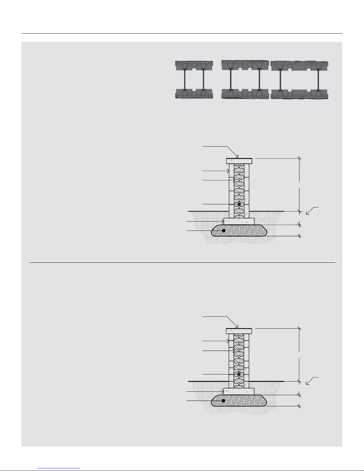
TYPICAL CROSS SECTION
A Capping unit (for double-sided wall)
B Veneer units
90 mm × 67 mm × variable
(3 9/16" × 2 5/8" × var)
C Double-sided connector
D 20 mm (3/4") clean stone
E Granular base 0-20 mm (0-3/4")
compacted 300 mm (12") min.
F Minimum buried depth 150 mm (6")
G Starter unit
90 mm × 200 mm × 400 mm
(3 9/16" × 7 7/8" × 15 3/4")
UNITS A – A
90 mm × 67 mm × 201 mm
(3 9/16" × 2 5/8" × 7 7/8")
UNITS B – B
90 mm × 67 mm × 268 mm
(3 9/16" × 2 5/8" × 10 1/2")
UNITS C – C
90 mm × 67 mm × 335 mm
(3 9/16" × 2 5/8" × 13 3/16")
UNITS D – D
90 mm × 67 mm × 402 mm
(3 9/16" × 2 5/8" × 15 13/16")
Page 20
20 – TANDEM® SYSTEM
A
D
F
G
E
C
B
A
D
F
G
E
C
B
TYPICAL CROSS SECTION
A Capping unit (for double-sided wall)
B Veneer units
180 mm × 67 mm × variable
(7 1/16" × 2 5/8" × variable)
C Double-sided connector
D 20 mm (3/4") clean stone
E
Granular base 0 -20 mm (0-3/4")
compacted 300 mm (12") min.
F Min. buried depth of 150 mm (6")
G Starter unit
90 mm × 200 mm × 400 mm
(3 9/16" × 7 7/8" × 15 3/4")
TYPICAL CROSS SECTION
A Capping unit (for double-sided wall)
B Veneer units
90 mm ou 180 mm × 67 mm × variable
(3 9/16" ou 7 1/16" × 2 5/8" × variable)
C Double-sided connector
D 20 mm (3/4") clean stone
E
Granular base 0 -20 mm (0-3/4")
compacted 300 mm (12") min.
F Min. buried depth of 150 mm (6")
G Starter unit
90 mm × 200 mm × 400 mm
(3 9/16" × 7 7/8" × 15 3/4")
BUILDING A DOUBLE-SIDED WALL
DOUBLE-SIDED LAFITT AND MELVILLE TANDEM WALL
WITH 180 mm VENEER UNITS
Note: Lafitt and Melville Tandem 180 wall modules must be
assembled using pairs of double-sided connectors installed one
on top of the other for greater stability.
DOUBLE-SIDED LAFITT AND MELVILLE TANDEM WALL
WITH 90 AND 180 VENEER UNITS
UNITS E – E
180 mm × 67 mm × 335 mm
(7 1/16" × 2 5/8" × 13 3/16")
UNITS F – F
180 mm × 67 mm × 402 mm
(7 1/16" × 2 5/8" × 15 3/16")
UNITS G – G
180 mm × 67 mm × 469 mm
(7 1/16" × 2 5/8" × 18 1/2")
180 mm (7 in)
300 mm (12 in) min.
180 mm (7 in)
720 mm (28 in) max
300 mm (12 in) min.
711 mm (28 in) max
Page 21
TANDEM® SYSTEM – 21
A
B
C
D
E
F
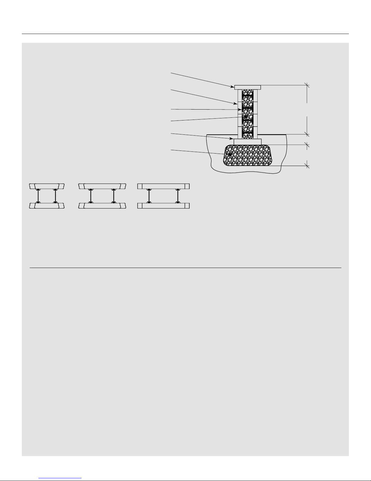
TYPICAL CROSS SECTION
A Esplanade chiseled capping unit,
60 mm × 381 mm × 1 067 mm
(2 3/8" × 15" × 42")
B Veneer units
180 mm × 60 mm × variable (350 mm, 495 mm, 562 mm)
(7 1/16" × 2 5/8" × var (13 3/4", 19 1/2", 22 1/8" ))
C Double-sided connector
D 20 mm (3/4") clean stone
E Starter unit 90 × 200 × 400 mm
F
Granular base 0 -20 mm (0-3/4")
compacted 300 mm (12") min.
BUILDING A DOUBLE-SIDED WALL
711 mm (28")
150 mm (6") min
300 mm (12") min
DOUBLE-SIDED ESPLANADE TANDEM WALL
UNITS E – E
180 mm × 60 mm ×
350 mm
(7 1/16" × 2 3/8" × 13 3/8")
UNITS F – F
180 mm × 60 mm ×
495 mm
(7 1/16" × 2 3/8" × 19 1/2")
UNITS G – G
180 mm × 60 mm ×
562 mm
(7 1/16" × 2 3/8" × 22 1/8")
Page 22
22 – TANDEM® SYSTEM
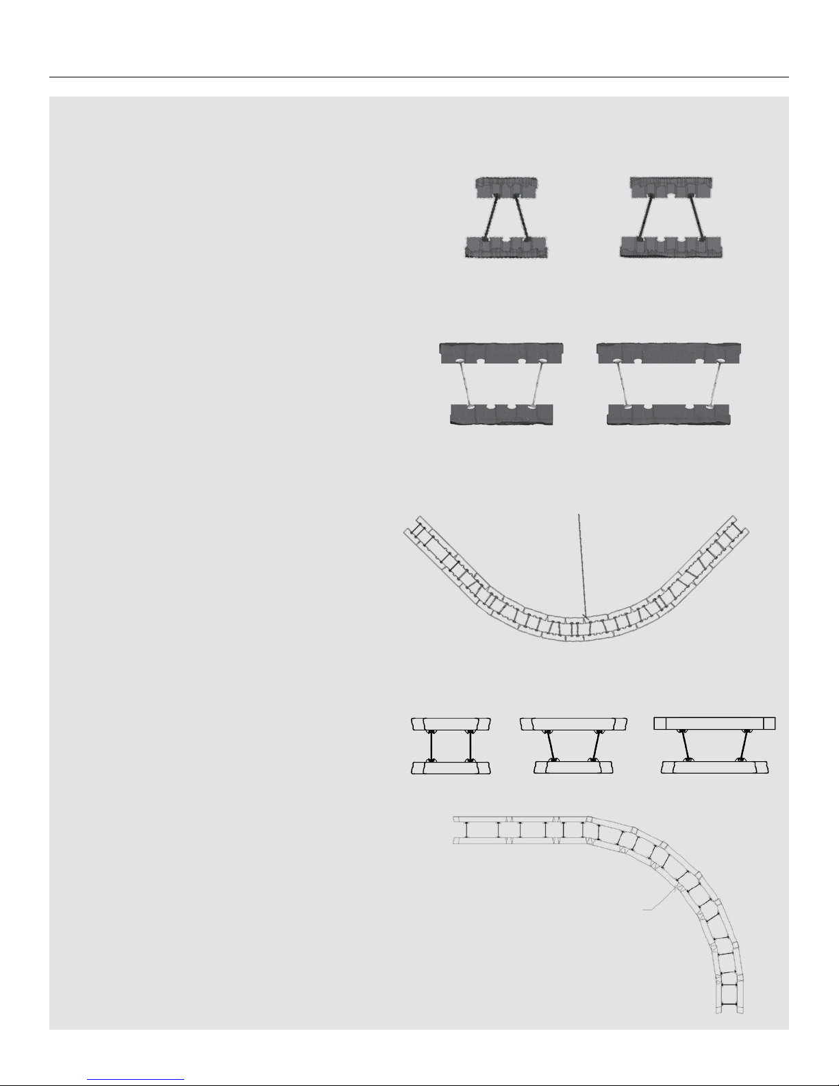
MODULES E – E MODULES E – F MODULES F – G
CURVED LAFITT AND MELVILLE TANDEM WALL
To build a curved double-sided wall, while maximizing results and minimizing
sizes, only the following pairs of veneer units are recommended for use:
A-A, A-B, B-B and B- C for 90 mm units and E-E, E-F, F-F and F-G for 180 mm
units. Consequently, there will be more D veneer units for the remainder of the
wall. Some units may have to be cut to fit perfectly into the selected curve.
The design flexibility of double-sided units means that connectors can be
inserted in all unit mor tises, providing for better adjustment in creating curves
with different radiuses.
Note: Lafitt and Melville Tandem 180 wall modules must be assembled using
pairs of double-sided connectors installed one on top of the other for greater
stability.
The minimum curves possible for the Lafitt Tandem wall:
- inner curves = 1.5 m (5.0 ft);
- outer curves = 1.8 m (6.0 ft).
Since Melville Tandem veneers all have a tex tured side,
the minimum bend radius is increased to 2.4 m (8 ft).
BUILDING A DOUBLE-SIDED WALL
R = 1 500 mm (60")
UNITS A – B UNITS B – C
UNITS E – F UNITS F – G
CURVED ESPLANADE TANDEM WALL
To build a curved double-sided wall, maximize results and
minimize sizes, we recommend using only the following veneer
unit pairs: E-E, E-F and F-G.
Note that the curves may vary depending on what units are
selected and how they are positioned. The minimum curve is
1500 mm (5 ft).
The flexibility of double-sided connectors is invaluable to
the construction of curved walls, since it is sometimes necessary
to offset the elements to adjust to the desired curvature.
DOUBLE-SIDED ESPLANADE TANDEM UNITS
FOR A CURVED WALL
R = 1 500 mm (60")
Page 23
TANDEM® SYSTEM – 23
#1
#1
#2
#2
ASSEMBLY FOR DOUBLE-SIDED 90 WALL:
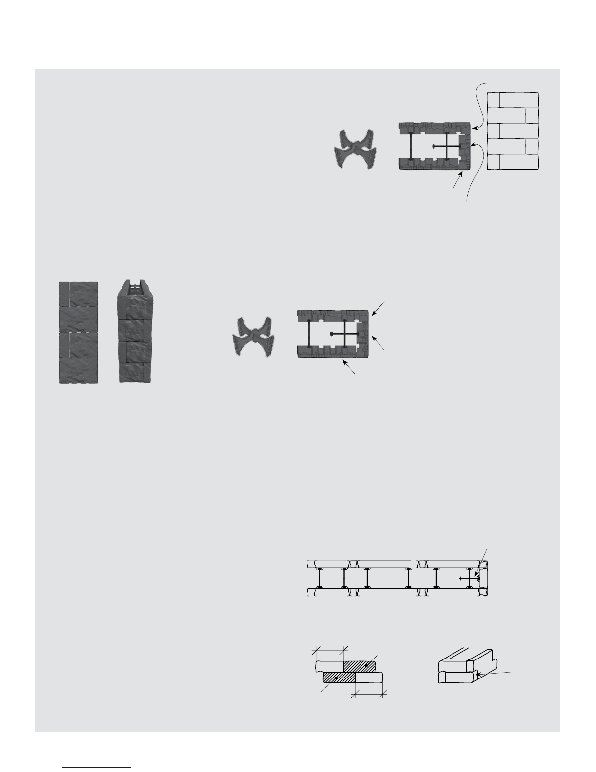
END OF WALL
Veneer
F (or G)
Tex tured ends
Textured end veneer
E
cut at 201 mm
Veneer
E (or F)
END OF DOUBLE-SIDED LAFITT
AND MELVILLE TANDEM WALL
The end of a double-sided Lafitt and Melville Tandem 90 wall is built using a
textured end veneer unit A installed on the end of the wall.
To ensure solid corner assembly, two double-sided connectors are
overlapped in a cross shape and inser ted into the mortises on the veneer units.
The first connector connects the two double-sided wall veneer units, while the
perpendicular connector connects the textured end veneer unit that forms
the end of the wall. Glue every course forming the end of the wall using
Permapro adhesive.
The end of a double-sided Lafitt and Melville Tandem 180 wall
is built using a textured end veneer unit E cut at 201 mm
and installed on the end of the wall.
ASSEMBLY FOR DOUBLE-SIDED 180 WALL:
END OF WALL
END OF A DOUBLE-SIDED LAFITT
AND MELVILLE TANDEM 90 AND 180 WALL
The end of a double-sided 90 and 180 wall is built by smoothly combining the
two kinds of construction (90 and 180) for a wall end, described previously in
this document. To build an end for a wall that mixes Tandem 90 and 180
units in the same wall, for each given row height, use units of the same height.
END OF A DOUBLE-SIDED
ESPLANADE TANDEM WALL
The end of a double-sided wall is built using a veneer unit F or G cut at 226 mm
and installed at the end of the wall (see ILLUSTRATION). For aesthetic reasons,
we recommend having the uncut end of the veneer unit face out.
BUILDING A DOUBLE-SIDED WALL
Connectors in
a cross shape
Plan viewIsometric view
Connectors installed
in a cross shape
Plan view
Elevation view
End of double-sided wall
- side view
Veneer A
Tex tured ends
226 mm (8.9")
Tex tured ends
Double-sided connector
Section to remove
Section to remove
Glue the unit joints
at the ends.
226 mm (8.9")
Veneer
F or G
Tex tured ends
Page 24
24 – TANDEM® SYSTEM
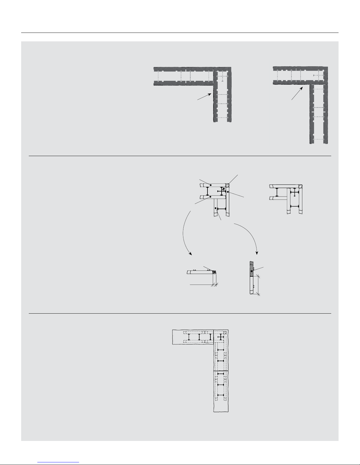
DOUBLE-SIDED WALL: 90° CORNERS
Building a 90º corner on a Lafitt and Melville Tandem wall
requires installing a wall end (described earlier), then juxtaposing
a second wall perpendicular to it.
Glue every course in the wall corner using Permapro adhesive.
Once again, for a natural look, avoid aligning vertical joints from
one row to the next on all visible surfaces.
90º CORNER IN A DOUBLE-SIDED 90
AND 180 WALL
Building a 90º corner on a wall requires installing a wall end
(described earlier), then juxtaposing a second wall perpendicular
to it. The second wall can be built starting with double-sided
Tandem 90 or 180 units. Adhere every course in the wall corner
using Permapro adhesive.
Corners are built using the options available for that height (90
or 180). These options were illustrated and explained earlier in
this document. The selection of corner module heights and their
positioning in the wall is a matter of aesthetics. The 90 and
180 units must be inserted in a similar proportion to the remainder
of the wall so that they harmonize.
90º CORNER IN A DOUBLE-SIDED ESPLANADE
TANDEM WALL
Building a 90º corner on a wall requires the assembly
described below.
Some components may have to be cut to adapt to the final anchor.
Veneer unit C or D only and
Veneer unit E or F only
to avoid placing a joint near
the junction between the two walls
Veneer unit 90 C or D only
Veneer unit 180 E or F only
To avoid placing a joint near the junction
between the two walls
1ST COURSE
and all odd course s
(Plan view)
2ND COURSE
and all even course s
(Plan view)
BUILDING A DOUBLE-SIDED WALL
Veneer
F cut
Veneer
G cut
Section to remove
60 mm (2.4")
Section to remove
335.88 mm
(13.2")
Veneer
G
Veneer
F
Double-sided
connector
1
ST
ROW 2ND ROW
CAPPING A DOUBLE-SIDED WALL
Double-sided Tandem walls are completed using Esplanade chiseled
capping units (60 × 381 × 1067 mm), laid side by side. Each unit
is textured on both sides (front and back), and one of two modules is
textured on one end. Modules can be rotated 180º for more flexibility.
To cap a 90° corner, simply install two capping units at a 90° angle.
For curved walls, capping units must be bevelled on site to match
the final shape of the wall.
Options: Straight and bevelled Celtik wall system capping units.
Note that all capping units must be attached to the last row
of Tandem units using Permapro concrete adhesive.
Page 25
TANDEM® SYSTEM – 25
BUILDING STAIRS
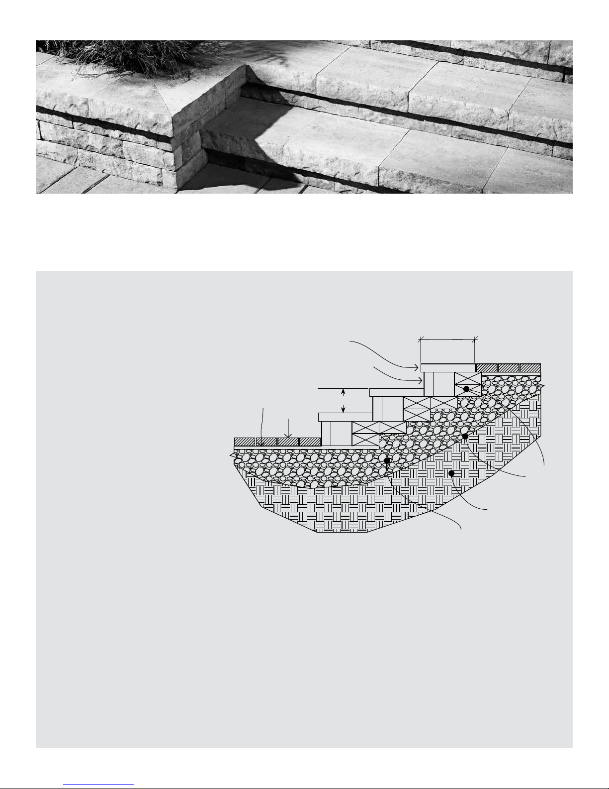
MELVILLE TANDEM STEP UNITS
To build Melville stairs, we suggest using Melville Tandem step unit
combined with the Melville Tandem unit (structural and veneer)
used as riser s.
A Melville Tandem step unit
60 mm × 400 mm × 600 mm
(2 3/8" × 15 3/4" × 23 5/8")
B Structural and veneer Melville Tandem unit
180 mm × 222 mm × variable
(3 9/16" × 8 3/4" × variable)
C Concrete paver 60 mm (2 3 /8" )
D 25 mm (1") bedding sand
E 0-20 mm (0-3/4") compacted aggregate base
F Existing soil
G Geotextile membrane
H Starter unit 90 mm × 200 mm × 400 mm
(3 9 /16" × 7 7/8" × 15 3/4")
All step and riser units must be glued together
using Permapro adhesive.
400 mm (15 3/4")
180 mm (7")
A
B
C
D
E
F
G
H
Page 26
26 – TANDEM® SYSTEM
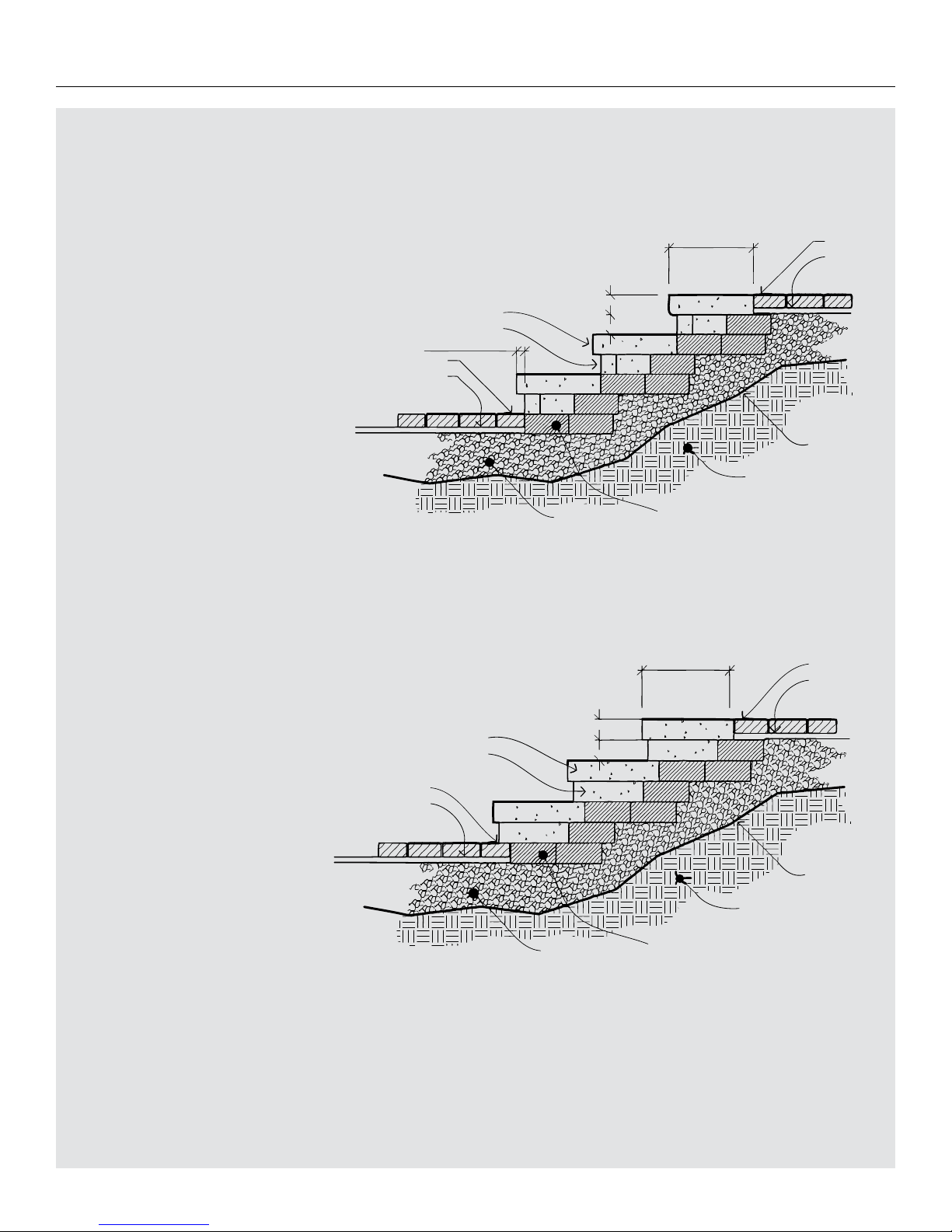
A
G
F
H
E
B
C
D
C
D
BUILDING STAIRS
OPTION 2
90 mm (3 9/16")
90 mm (3 9/16
"
)
400 mm (15 3 /4")
A
G
F
H
E
B
C
C
D
D
OPTION 1
400 mm (15 3 /4")
90 mm (3 9/16")
90 mm (3 9/16")
25 mm (1")
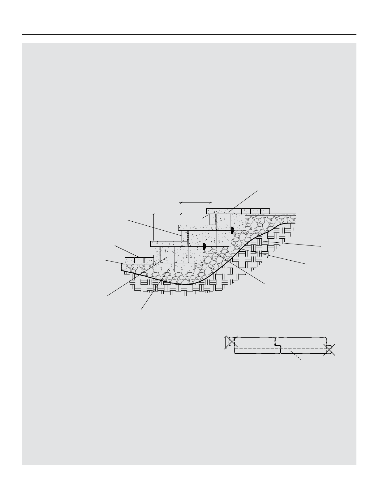
LAFITT TANDEM STEP UNITS
To build stairs, it is recommended that the step unit be used in
combination with one of the following options for the riser:
A Lafitt Tandem step unit
90 mm × 400 mm × 400 mm
(3 9/16" × 15 3/4" × 15 3/4" )
B Option 1
Structural unit and Laffit Tandem veneer
90 mm × 222 mm × variable
(3 9/16" × 8 3/4" × variable)
Option 2
Lafitt Tandem straight capping unit
90 mm × 305 mm × 400 mm
(3 9/16" × 12" × 15 3/4")
C Concrete paver
60 mm (2 3/ 8") or 80 mm (3 1/8" )
D 25 mm (1") bedding sand
E 0-20 mm (0-3/4") compacted aggregate base
F Existing soil
G Geotextile membrane
H Starter unit 90 mm × 200 mm × 400 mm
(3 9/16" × 7 7/8" × 15 3/4")
All step and riser units must be glued together
using Permapro adhesive.
Page 27
TANDEM® SYSTEM – 27
A
B
C
E
E1E
E1E
E1
E2
E2
E2
F
G
I
H
BUILDING STAIRS
ESPLANADE TANDEM STEPS
When building Esplanade Tandem stairs, we suggest using chiseled Esplanade
capping as a component, combined with the Esplanade Tandem units used as risers.
Additional structural units are used to reinforce the structure with additional support.
All step and riser units must be glued together using Permapro adhesive.
Esplanade step detail
A Chiseled Esplanade capping unit
60 mm × 381 mm × 1067 mm
(2 3/8" × 15" × 42")
B Concrete paver 60 mm (2 3/ 8") or 80 mm (3 1/8" )
C Bedding sand 25 mm (1")
D Veneer unit 180 × 60 mm × variable (350, 495, 562 mm)
7" × 2 3/8" × var (13 13/16", 19 1/2", 22 1/8")
E Structural unit 180 × 155 mm × variable (335, 402, 469 mm)
7" × 6 1/8" × var (13 3/16", 15 7/8", 18 1/2")
F Starter Unit (90 × 200 × 400 mm)
G 0-20 mm (0-3/4") compacted aggregate base
H Geotextile membrane
I Existing soil
Part to remove
* Veneer units must be cut to a height of 120 mm
and at either end (as needed)
Detail 1
120 mm
Note: Structural units E and E1 are installed back to back. The unit E1 tenons must be removed.
The unit E2 tenons must be removed to avoid a conflict with the setback anchors on the unit
above. Unit E2 rests on unit E1.
D
(see Detail 1)
38 mm
(1 1/2 in)
311 m m
(12 1/4 in)
311 m m
(12 1/4 in)
Page 28
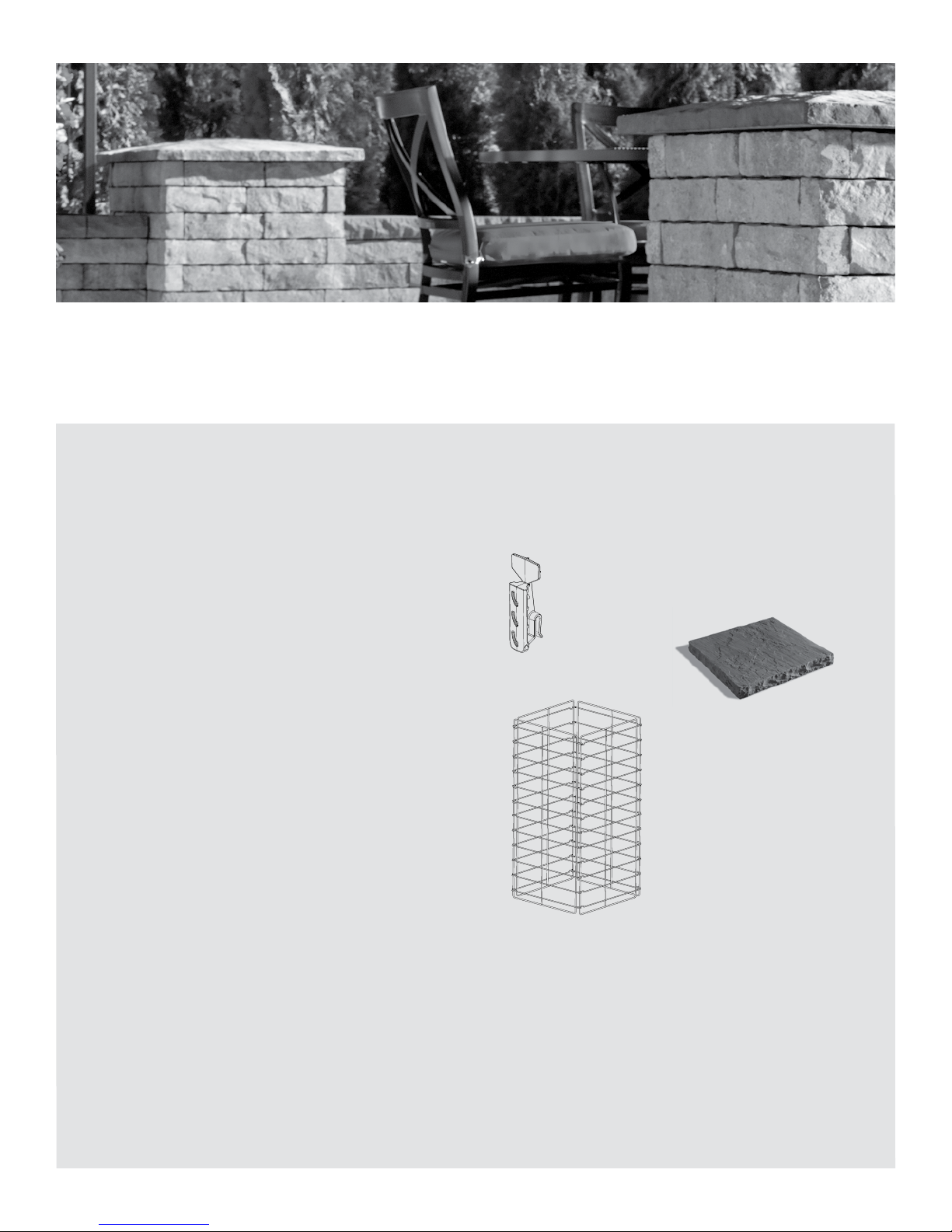
ESPLANADE CAPPING
PILLAR MODULE (29" × 29")
GRID CONNECTORS
200 UNITS PER BAG
1 PILLAR GRID
With this material, you can construct one Pillar:
670 mm × 670 mm (26 3/8" × 26 3/8") of 1080 mm in height (42 1/2").
One Pillar requires the use of 2.6 m
2
(28 ft2) of Veneer units.
One cube contains 10 Pillar grids and 10 bags of 200 grid connectors.
Note : All Melville veneer units come with
one textured end (corner units)
90 mm LAFIT T TANDEM
VENEER UNITS:
48 REGULAR UNITS
(12A, 12B, 12C, 12D)
48 CORNER UNITS
(12A, 12B, 12C, 12D)
28 – TANDEM® SYSTEM
This section discus ses the different types of pillars which can be built
using the Tandem system, namely:
Tandem pillars with steel pillar grids
Tandem pillars with structural modules
Tandem veneer units are used for the exterior facing of the pillar.
The interior core of the column serves a structural function and
can be built in accordance with one of the following two methods:
using structural units (regular Tandem system) or using a steel pillar
grid instead of structural units.
TANDEM PILLARS WITH PILLAR GRIDS
That type of pillar is built with Lafitt and Melville Tandem veneer units only.
The building of this type of column begins with the use of a steel pillar grid
which provides structural suppor t for the veneer units. The units are fastened
to the pillar grid using specially-designed connectors.
The essential details for building this type of pillar
are described below.
BUILDING PILLARS
90 mm LAFITT AND MELVILLE TANDEM COLUMN
WITH PILLAR GRID ASSEMBLY
MATERIAL NEEDED:
Page 29
TANDEM® SYSTEM – 29
BUILDING PILLARS
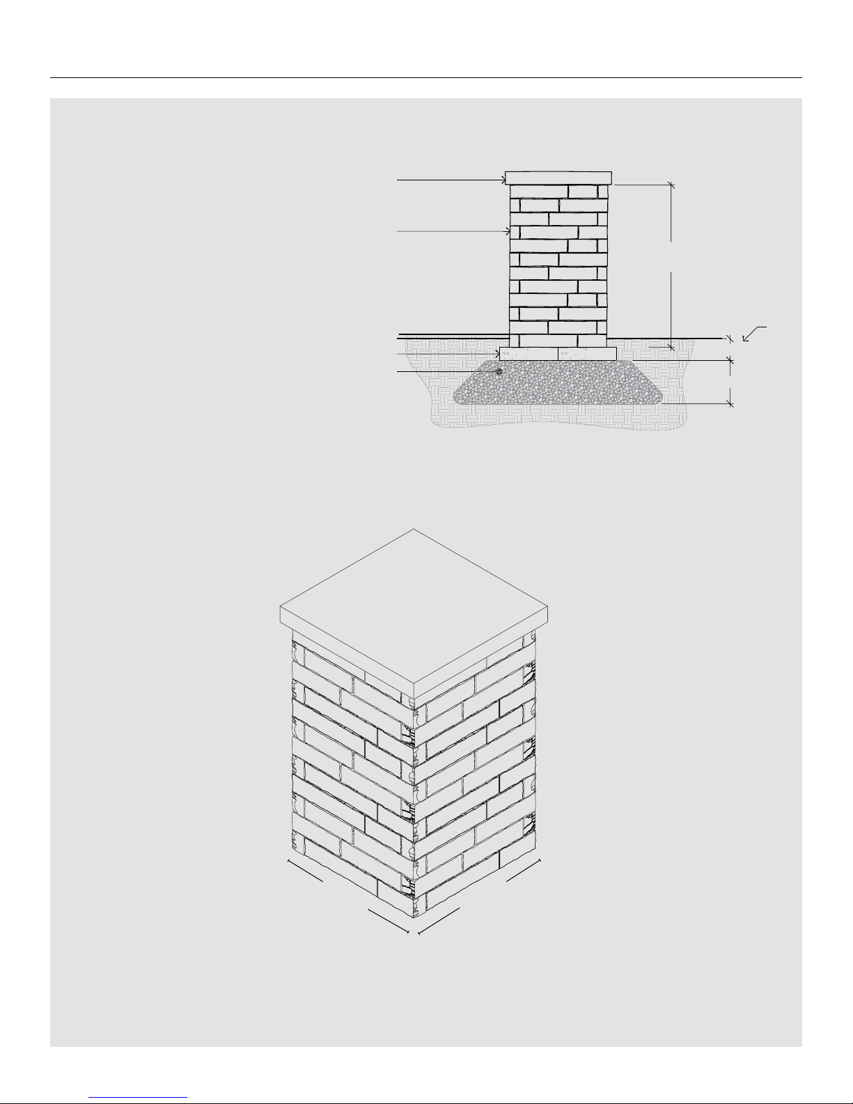
LAFITT OR MELVILLE TANDEM PILLAR GRID –
CROSS SECTION
A Esplanade Capping Pillar Module (29" × 29")
B 90 mm Lafitt or Melville Tandem Veneer unit
C Starter unit
D 0-20 mm compacted granular Foundation, 300 mm (12")
E Minimum Embeded Soil, 150 mm (6")
B
A
C
D
E
Max height
1080 mm (42 1/2")
150 mm (6")
300 mm (12" min.)
670 mm
(26 3/8 in)
670 mm
(26 3/8 in)
Page 30
30 – TANDEM® SYSTEM
BUILDING PILLARS
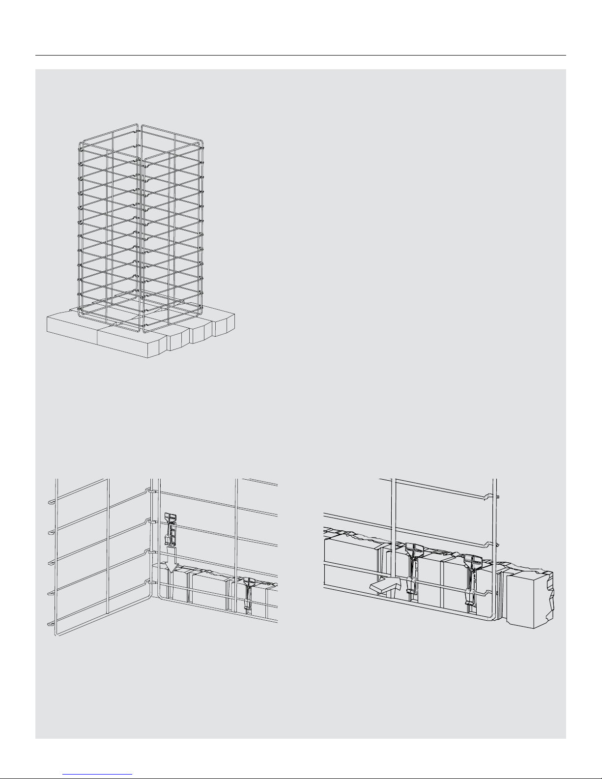
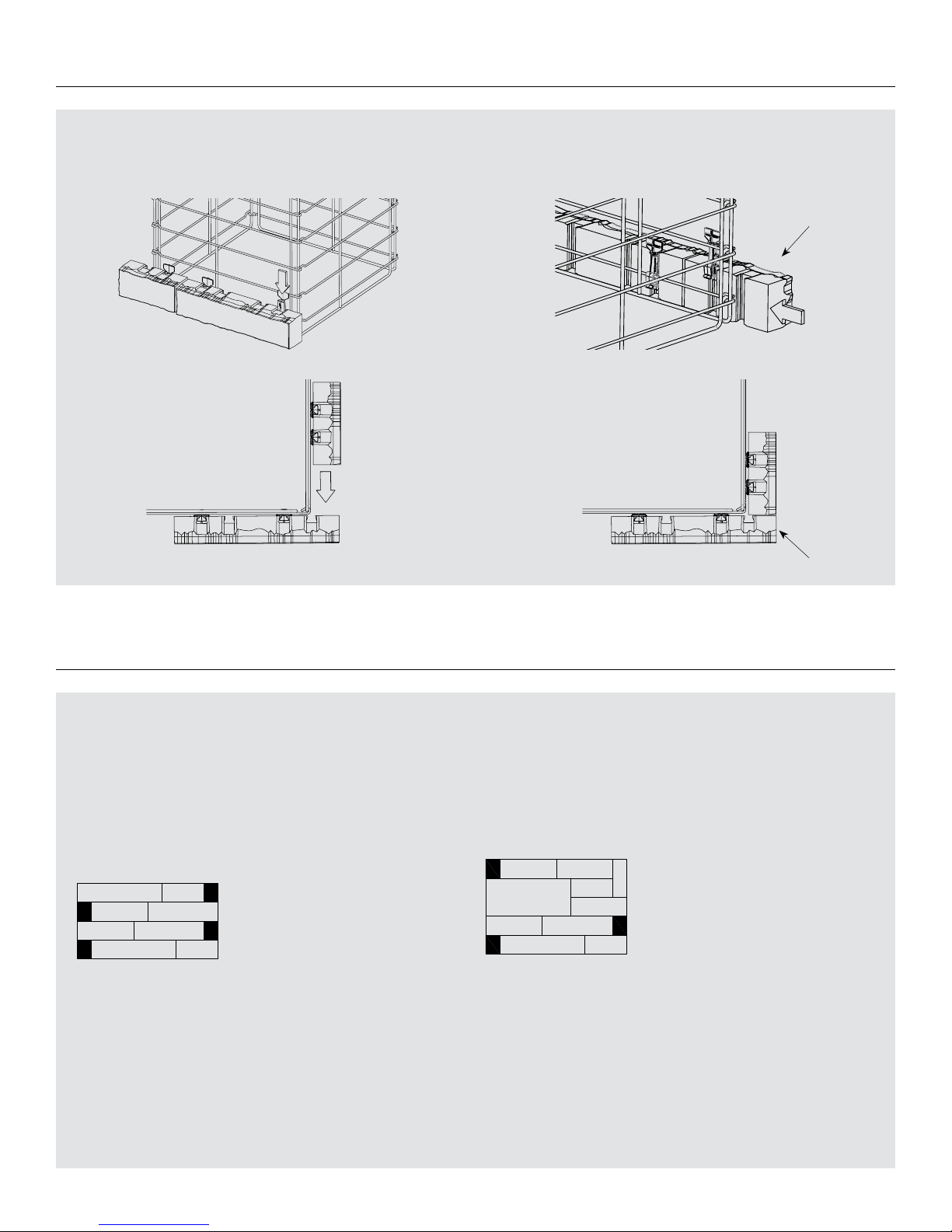
Begin by placing a row (8 units) of starter units on a base of
compacted crushed stone. Unfold the steel pillar grid and place it
on the prepared surface.
Insert the pillar connectors (using 2 connectors for each unit) into
the veneer units which form the first row of the pillar. Place the
veneer units for the first row around the steel pillar grid, making
sure to “click” the connectors onto the horizontal wires (refer to the
recommended installation pattern for the veneer units which have
been selected).
1ST ROW OF STARTER UNITS
Page 31
B B
5TH ROW
TANDEM® SYSTEM – 31
D
D
C
C
A
A
B
B
D
B
C
A
D
CB
A
B
A
F
E
A
B
A
D
BUILDING PILLARS
LAYING PATTERN
The corners of the pillar can be built easily by sliding the units
along the wire until they line up with the corner unit which was
installed previously.
Suggested installation pattern for the optimal use of the Tandem
veneer units.
2ND ROW
3
RD
ROW
4
TH
ROW
1
ST
ROW
2
ND
ROW
3
RD
ROW
4
TH
ROW
1
ST
ROW
FIRST 4 ROWS
(OVER THE STARTER UNITS)
360 mm (14 in)
FIRST 5 ROWS
(OVER THE STARTER UNITS)
(FOR REFERENCE ONLY)
INSTA LLATION PATT ERN TO REPEAT
UP TO DESIRED HEIGHT (FRONT VIEW)
INSTA LLATION PATT ERN TO REPEAT
UP TO DESIRED HEIGHT (FRONT VIEW)
TANDEM PILLAR WITH 90 mm UNITS
90 mm TANDEM PILLAR
WITH 180 mm UNITS
Corner Venee r Unit
Corner Venee r Unit
Page 32
32 – TANDEM® SYSTEM
BUILDING PILLARS
90 mm LAFITT OR MELVILLE TANDEM PILLAR
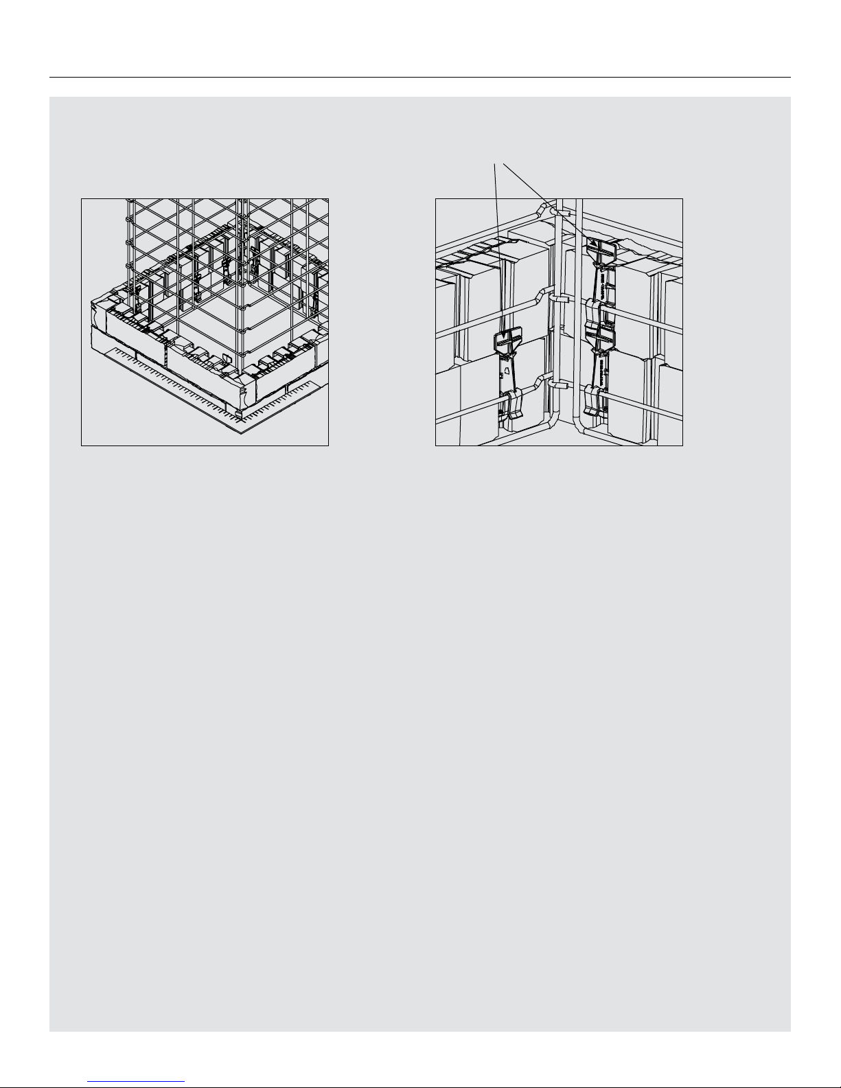
Once the first row has been completed, fill the interior space with
clean 20 mm aggregate, and then use a square to ensure that the
corner units are perpendicular to each other. Repeat this step after
every second row has been completed. Install subsequent rows in
the same manner, up to the desired height.
Ensure that the upper part of each connector is firmly in place
behind the veneer unit, since it will serve as a suppor t for the unit
which will be installed above it.
Upper part of the connector
Page 33
TANDEM® SYSTEM – 33
A
C
C
D
D
B
B
A
A
A
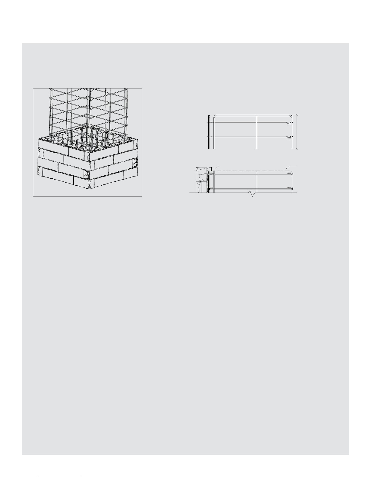
CUTTING INSTRUCTION OF PILLAR GRID (front view)
To build a pillar which is shorter than 1067 mm (42"), simply cut
away the exces s portion of the steel pillar grid with a grinder.
This is the recommended installation procedure for building
the first four rows of a pillar; it makes optimal use of the veneer
formats within a pallet: 16 regular Veneers and 16 Veneers
with a texture end.
Repeating this pattern two more times will build a pillar with
12 rows and a height of 42 1/ 2 inches.
Cutting line
UNNECESSARY
upper part
to be cut
15 mm Minimum
BUILDING PILLARS
Page 34
BUILDING PILLARS
34 – TANDEM® SYSTEM
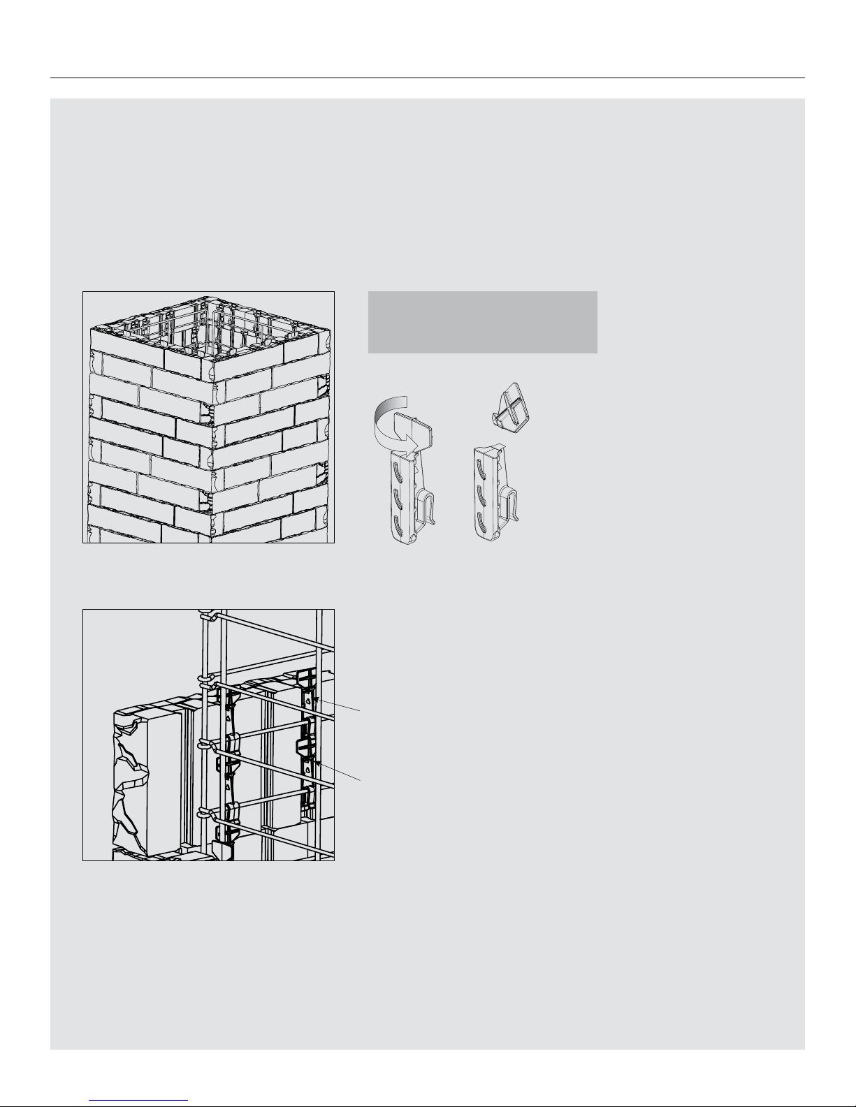
A full steel pillar grid can be used to build a pillar with an overall
height above ground, including the capping unit, of 1067 mm
(42").
When the last row is reached, cut off the tops of the connectors
with sheet-metal shears or twist them off by hand. Then install
the capping unit on the pillar, adhering it in place with glue.
Important note: the capping unit must rest on the veneer units
and not on the steel pillar grid.
Upper connector
Lower connector
When using 180 mm high veneer units, use four connectors
as shown below, beginning with the two lower ones and ending
with the two upper ones.
To integrate 180 mm units into a pillar, use only 180 mm
E and F units with textured corners. Carefully place the veneer units
so that the joints are staggered, and ensure that you place at least
one 180 mm unit on each side of the pillar, and not more than two.
LAFITT TANDEM PILLAR 90 and 180 mm VENEER UNITS
* Important note: the Capping unit must
rest on the veneer units and not on the
steel Pillar grid
Page 35
BUILDING PILLARS
TANDEM® SYSTEM – 35
JOINING A DOUBLE-SIDED WALL
TO A PILLAR
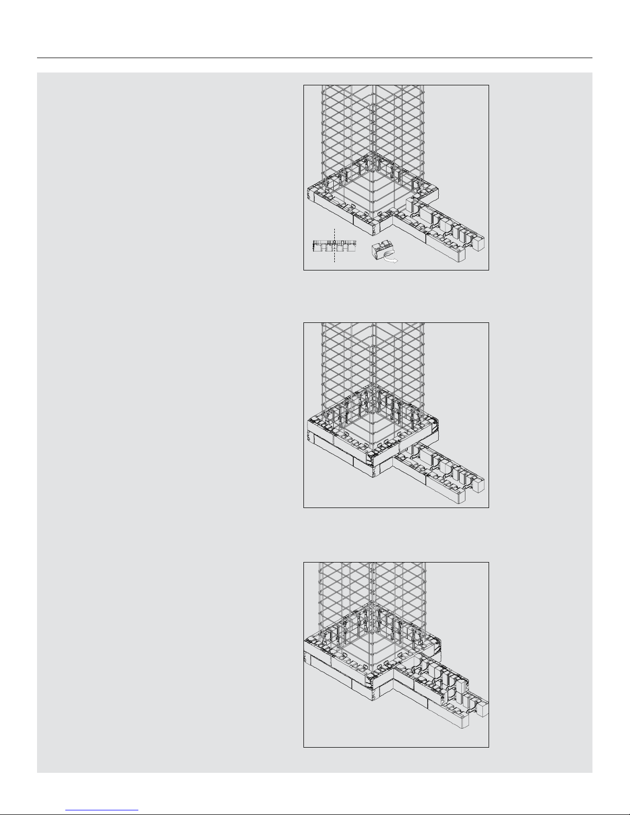
To join a double-sided wall to a pillar, you must cut the veneer unit
for the pillar at every second row. Cut it at the centre of the dovetail
recess.
For the second row, run the unit across the double -sided wall.
Begin the second row of the double-sided wall from the face of the pillar.
Page 36
BUILDING PILLARS
TANDEM PILLAR WITH STRUCTURAL UNITS
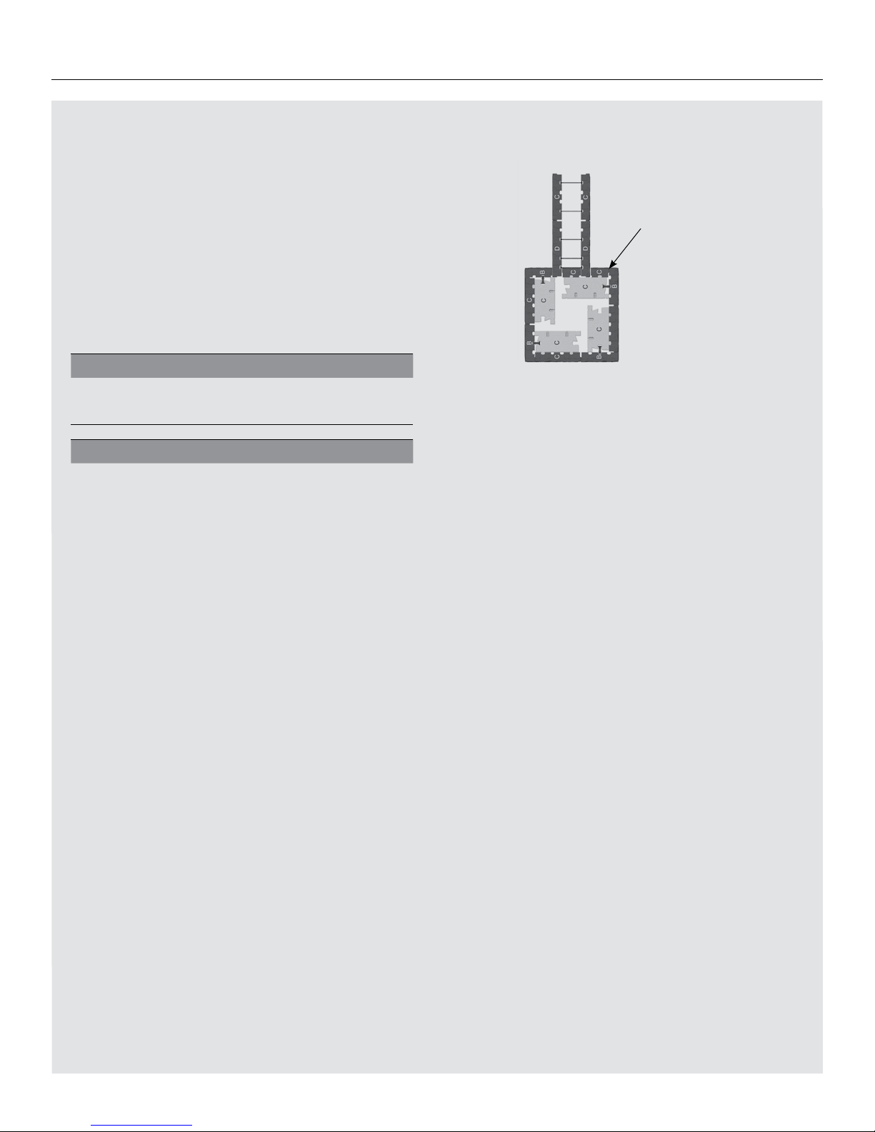
Three types of pillar can be built :
•
La fit t Ta ndem
•
Melville Tandem
•
Esplanade Tandem
Pillars are built by placing Tandem units at 90° angles to create a square. Corners can
then be completed by adding the appropriate textured veneer units. These veneers are
attached using a corner connector as mentioned in the section on building a corner. It is
advisable to glue each module together for every course.
Several different sizes of pillar can be built by using either 90 mm units or 180 mm units.
Maximum pillar height range s from 1200 mm to 1500 mm (4 to 5 ft) above ground level
with a minimum buried depth of 150 mm (6"). Capping is completed using the various
Esplanade capping units from Permacon (see the table below):
PILLAR 90 UNIT
ESPLANADE CAPPING MAXIMUM HEIGHT
670 mm × 670 mm
(26 3/8 in × 26 3/8 in)
737 mm × 737 mm
(29 in × 29 in)
1200 mm
(4 ft)
737 mm × 737 mm
(29 in × 29 in)
787 mm × 787 mm
(31 in × 31 in)
1500 mm
(5 ft)
PILLAR 180 UNIT
ESPLANADE CAPPING MAXIMUM HEIGHT
737 mm × 737 mm
(29 in × 29 in)
787 mm × 787 mm
(31 in × 31 in)
1200 mm
(4 ft)
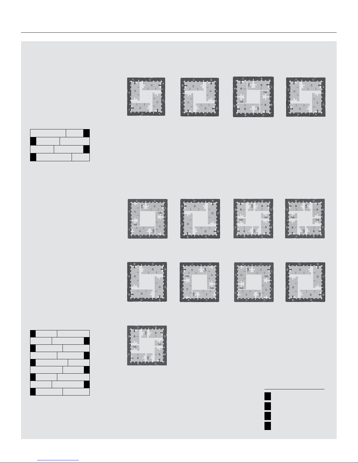
The predetermined installation patterns which are provided are intended to facilitate the
building of each type of pillar. They also permit the optimal use of the different Tandem
modules and the textured veneer units.
In all cases, it is important to avoid aligning ver tical joints from one row to the next
on all visible façades. For these reasons, some combinations should be avoid from row
to another.
Note that for some combinations, you need to use a structural unit A cut in two
and fitted together with the veneer units.
When a double-sided wall ends at a pillar, the pillar must be modified to ensure it is
solidly embedded, as in the following illustration:
Veneer pillars cut ever y two layers
to embed the double-sided wall.
EXAMPLE OF EMBEDDING
36 – TANDEM® SYSTEM
Page 37
TANDEM® SYSTEM – 37
B
B
B
B
B
B
D
D
D
D
D
D
C
C
C
C
C
C
D
C
B
D
C
B
C
D
B
D
D
B
B
C
C
A
A
D
B
C
A
LAFITT AND MELVILLE TANDEM PILLARS
WITH 90 mm UNITS
VENEER A WITH
TEXTURED END
1
ST
ROW
1
ST
ROW
5
TH
ROW
9
TH
ROW
VENEER B WITH
TEXTURED END
VENEER D WITH
TEXTURED END
VENEER C WITH
TEXTURED END
VENEER B WITH
TEXTURED END
2
ND
ROW
2
ND
ROW
6
TH
ROW
VENEER C WITH
TEXTURED END
VENEER B WITH
TEXTURED END
VENEER B WITH
TEXTURED END
VENEER C WITH
TEXTURED END
VENEER C WITH
TEXTURED END
3
RD
ROW
3
RD
ROW
7
TH
ROW
VENEER D WITH
TEXTURED END
VENEER D WITH
TEXTURED END
VENEER D WITH
TEXTURED END
4
TH
ROW
4
TH
ROW
8
TH
ROW
PILLAR
670 mm × 670 mm
(26 3/8 in × 26 3/8 in)
PILLAR
737 mm × 737 mm
(29 in × 29 in)
INSTA LLATION PATT ERN TO REPEAT
UP TO DESIRED HEIGHT
(FRONT VIEW)
FIRST 4 ROWS
360 mm (14 13/16 in)
1ST ROW
2
ND
ROW
3
RD
ROW
4
TH
ROW
INSTA LLATION PATT ERN TO REPEAT
UP TO DESIRED HEIGHT
(FRONT VIEW)
FIRST 9 ROWS
810 mm (31 7/8 in)
5TH ROW
4
TH
ROW
9
TH
ROW
3
RD
ROW
8
TH
ROW
2
ND
ROW
7
TH
ROW
1
ST
ROW
6
TH
ROW
D
C
B
A
LEGEND
VENEER D WITH TEXTURED END
VENEER C WITH TEXTURED END
VENEER B WITH TEXTURED END
VENEER A WITH TEXTURED END
BUILDING PILLARS
Page 38
38 – TANDEM® SYSTEM
EEE
E
E
EEE
E
E
E
E
BUILDING PILLARS
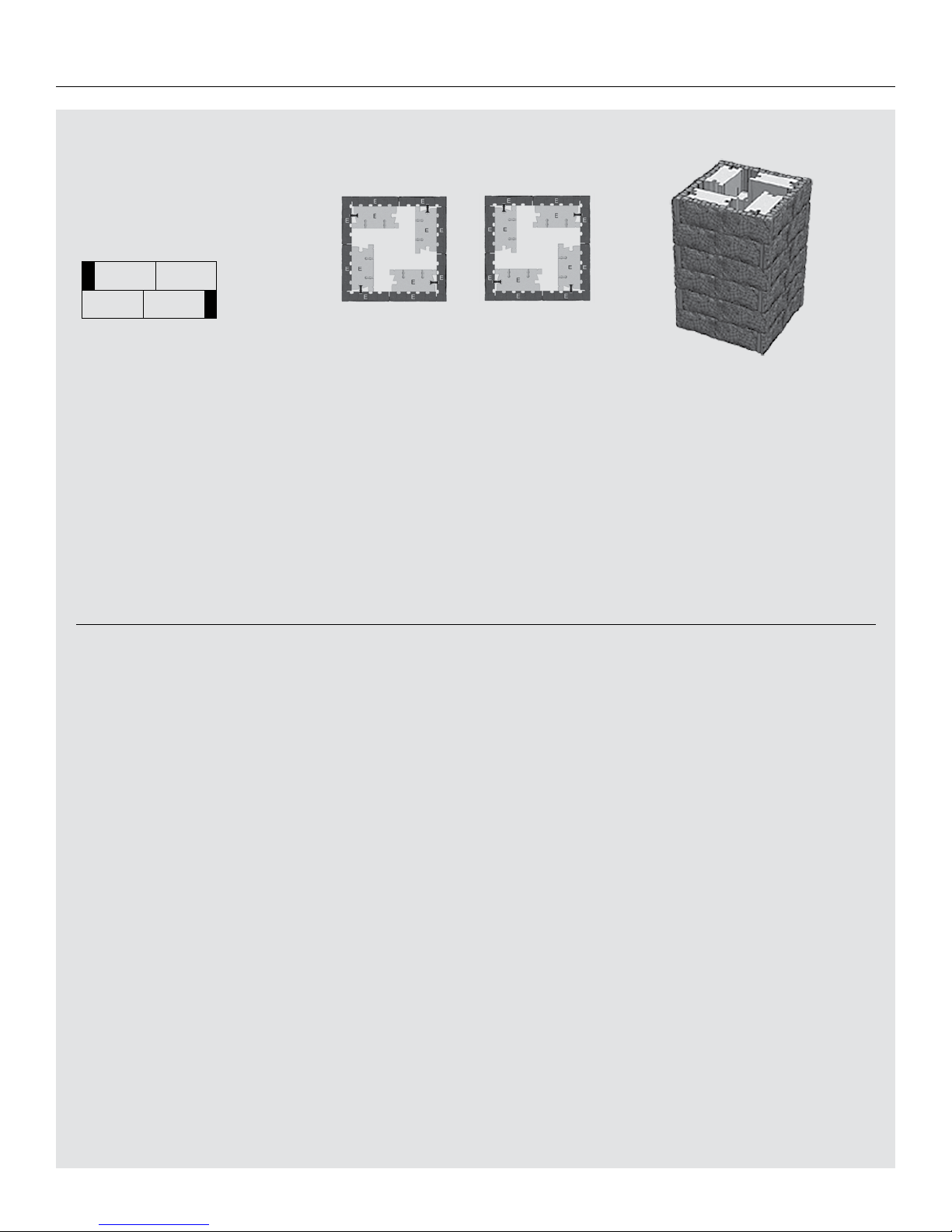
PILLARS WITH TANDEM 90 AND 180 UNITS
Note that it is possible to build a pillar using a mix of 90 and 180 units, but no pattern has been defined.
We recommend only using 90 mm structural units to build the inside of this type of pillar and by using
the 180 mm Lafitt veneer units E and F.
LAFITT AND MELVILLE TANDEM PILLARS
WITH 180 mm UNITS
FIRST ROW AND
EVERY ODD ROW
TEXTURED END
VENEER UNIT
SECOND ROW AND
EVERY EVEN ROW
TEXTURED END
VENEER UNIT
PILLAR
737 mm × 737 mm
(29 in × 29 in)
INSTA LLATION PATT ERN TO REPEAT
UP TO DESIRED HEIGHT
(FRONT VIEW)
FIRST 2 ROWS
360 mm (14 13/16 in)
2ND ROW
1
ST
ROW
Page 39
TANDEM® SYSTEM – 39
BUILDING PILLARS
ESPLANADE TANDEM PILLARS
The pillars are built by two Esplanade Tandem units (F or G) facing each other to form
the front and back surfaces of the pillar. Two veneers are then installed and attached
on either side of the structural units, using the corner connectors. This forms the first
course of the pillar. The second course repeats the first course, placed at a 90° angle.
We recommend attaching the units together using adhesive on every course.
It is possible to build 2 different pillar sizes. The maximum height of one pillar ranges
from 1200 mm to 1500 mm (4 to 5 f t) above ground, with a minimum buried depth of
150 mm (6"). The capping is added using the various Esplanade capping units from
Permacon (see table below)
ESPLANADE
PILLAR
ESPLANADE
CAPPING
MAXIMUM
HEIGHT
555 mm × 555 mm
(21 7/8 in × 21 7/8 in)
635 mm × 635 mm
(25 in × 25 in)
1200 mm
(4 ft)
ESPLANADE
PILLAR
ESPLANADE
CAPPING
MAXIMUM
HEIGHT
622 mm × 622 mm
(24 1/2 in × 24 1/2 in)
686 mm × 686 mm
(27 in × 27 in)
1500 mm
(5 ft)
In all cases, avoid aligning joints vertically from row to row on all visible surfaces.
DOUBLE-SIDED WALL
EMBEDDED IN A PILLAR
DETAIL #1 ON VENEER TO CUT
Detail #1 on
veneer to cut
83 mm
(3.3")
90 mm
(3.5")
PILLAR 555 mm × 555 mm
Structural unit F and Veneer unit F
555 mm (21,9" )
622 mm (24,9" )
PILLAR 622 mm × 622 mm
Structural unit G and Veneer unit G
1
ST
ROW
1
ST
ROW
2
ND
ROW
2
ND
ROW
83 mm
(3,3")
90 mm
(3,5")
60 mm
(2.4")
60 mm
(2.4")
135 mm (5 1/4" ) Veneer F
168 mm ( 6 5/8" ) Veneer G
135 mm (5 1/4" ) Veneer F
168 mm ( 6 5/8" ) Veneer G
Page 40
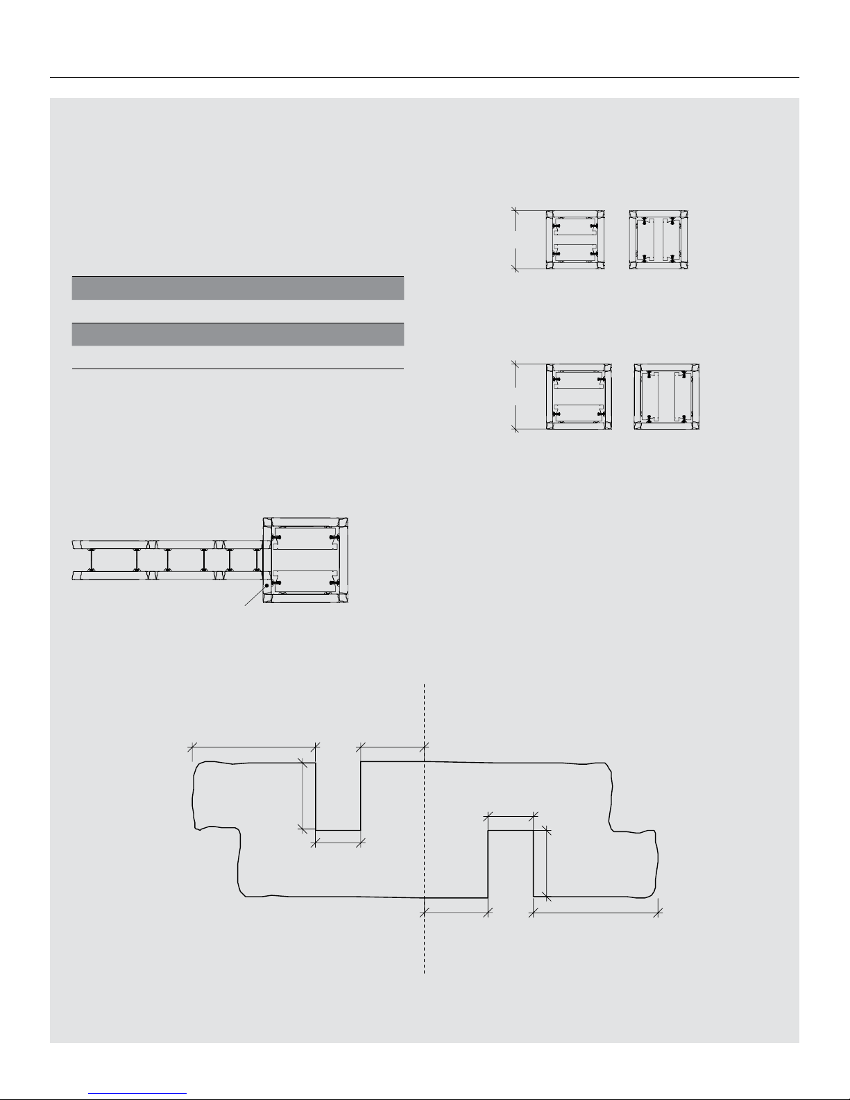
CONSTRUCTION OF OUTDOOR LIVING
COMPONENTS WITH THE NEW TANDEM
MODULAR GRID (GENERALITY)
40 – TANDEM® SYSTEM
The Tandem system allows you to install different outdoor living
components such as outdoor kitchens (barbecue, fridge, bar),
patio furniture (bench and table), flower box, outdoor gas fireplace,
privacy wall, fencing and deck skirting.
You can easily build all these features if you use
the new Tandem modular grid.
Our system has multiple benefits:
• Provides a unified look for all the features of the landscaping design.
• Provides a durable, economical and maintenance-free solution.
• Offers great flexibility and unrestricted creativity regarding
the configuration and size of components to be constructed.
• Offers a solution to difficult issues (e.g. deck skirting).
• Eliminates the use of cementitious products (mortar).
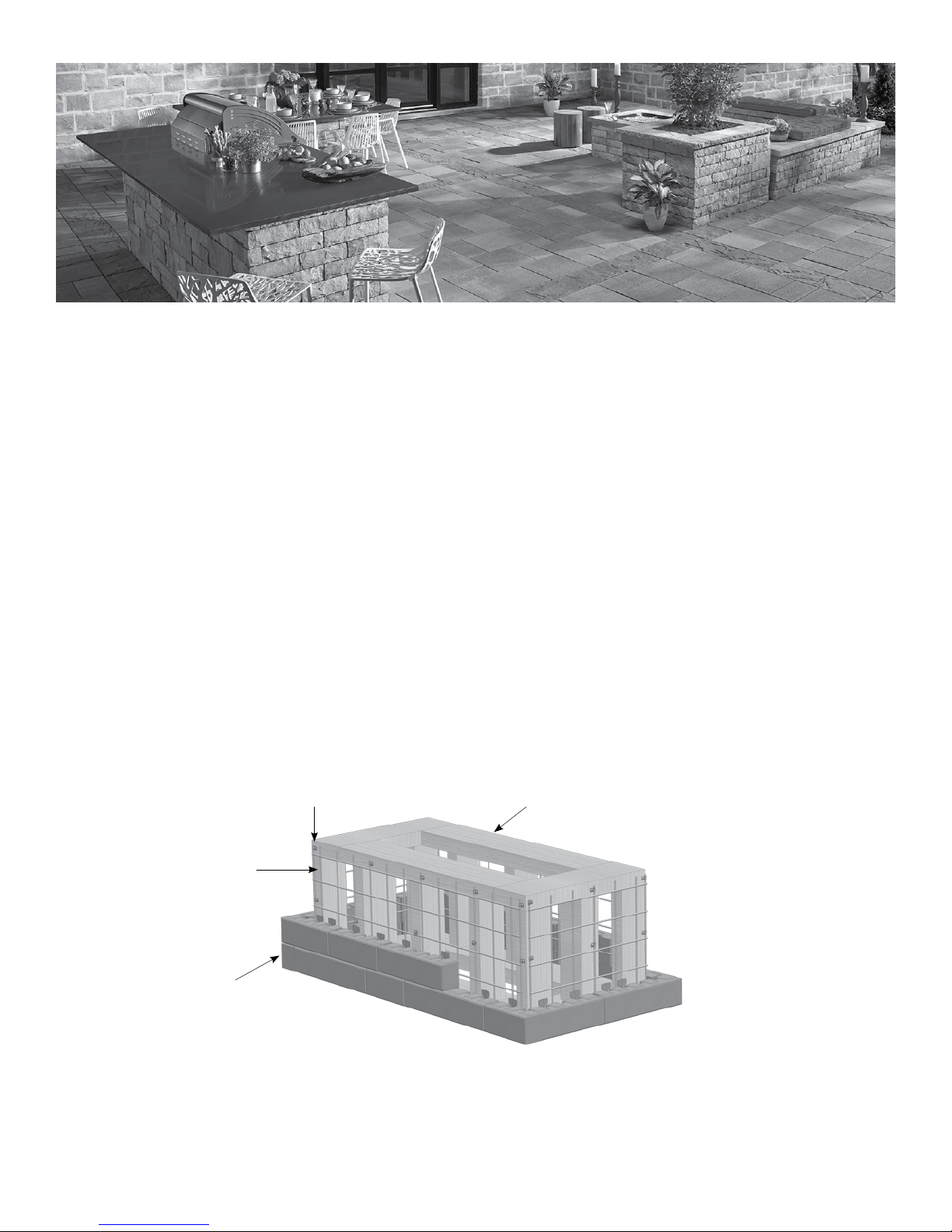
Wooden structure
(2 × 4 or 2 × 6)
Screw and loop clamp
Tandem modular grid
Tandem veneer units
(with grid connectors)
Page 41

TANDEM® SYSTEM – 41
CONSTRUCTION OF OUTDOOR LIVING COMPONENTS WITH THE TANDEM MODULAR GRID
Basic Principles
A set of Tandem modular grids is attached to a structure of treated wood
to which are attached Tandem veneer units (Lafitt or Melville). Since
veneer units are manufactured in multiples of 67 mm, the overall
dimensions of outdoor units should always be a multiple of 67 mm in
order to avoid cuts. The wooden structure should be built taking into
account the modular design of Tandem veneers. The same applies to the
height, which must be a multiple of 90 mm. The item is finished off with
an appropriate capping module. You can construct a range of outdoor
units of various dimensions.
Main components of the system
• Tandem modular grid, 720 mm × 1080 mm (28" × 42 1/2"),
including stainless steel screws and Loop clamps for fastening.
A modular grid covers a facing surface of 0.78 m² (8.40 sqft).
Each modular grid includes a kit of 60 connectors, 10 × 1 1/4" screws
and 10 loop clamps.
• Tandem veneer units (Lafitt or Melville).
• Galvanized shelf angle (for deck skirting, privacy walls
and fences) 2 1/2" × 2 1/2" × 8' (min 10 gauge, Z275 G90 galvanized
steel, ASTM A653 Grade 33).
• Permacon concrete capping module
(Lafitt, Melville and Esplanade Tandem, Mondrian).
Other components not supplied by Permacon
• Treated Wood: 2x4, 2x6 and 2x8 boards, 4x4 or 6x6 posts,
4x8 plywood sheets (all wood should be treated against rot
and must be category S-P-F #1 or better). Refer to the various
suppliers’ specific application sheets for details.
• Fiber cement panels 1220 mm × 2240 mm × 12 mm
(48" × 96" × 1/2").
• #10 screws of varying lengths, nuts, bolts and washers where required,
all in stainless steel. It is not recommended to use treated wood
screws (green ceramic) or metal plated screws (zinc, copper or other).
• Hilti Kwik Bolt-type anchors (for concrete deck skirting)
• Simpson Strong-Tie-type hardware for construction
of wood frame for deck.
• Custom countertops made of granite, quartz, marble
and natural stone as alternatives to concrete tops.
Page 42

42 – TANDEM® SYSTEM
CONSTRUCTION OF OUTDOOR LIVING COMPONENTS WITH THE TANDEM MODULAR GRID
WOOD FRAMING
You must always take the modular design of Tandem veneers into account
when constructing wood framing. The overall dimensions of outdoor units
must always be a multiple of 67 mm in length and width and 90 mm
in height. When installing the framing, remember that grids need a
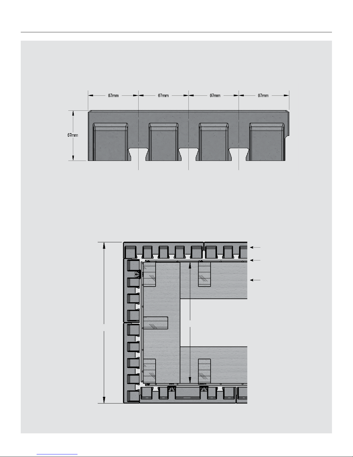
16 mm (5/8") space between the veneer and the frame.
Bearing this in mind, the following tables show detailed measurements
for the framing of units. These tables are very useful for quickly calculating
the actual dimensions of the wood framing and the unit to be constructed
to build the component without any veneers cut.
Table of component and its wood frame dimensions
based on the modular format of veneers
DIM A (mm) DIM A (in) DIM B (mm) DIM B (in)
201 7 15 /16 35 1 3/8
268 10 9/16 102 4
335 13 3/16 169 6 5/8
402 15 13/16 236 9 5/16
469 18 7/16 303 11 15/16
536 21 1/8 370 14 9/ 16
603 23 3/4 437 17 3/16
670 26 3 /8 504 19 13/16
737 29 571 22 1/2
804 31 5/ 8 638 25 1/8
871 34 5 /16 705 27 3 /4
938 36 15/16 772 30 3 /8
1005 39 9/16 839 33 1/16
1072 42 3 /16 906 35 11 /16
1139 4 4 13 /16 973 38 1/4
1206 47 1/2 10 40 40 15/16
1273 50 1/8 1107 43 9 /16
1340 52 3/4 1174 46 1/4
1407 55 3/8 1241 48 7/8
1474 5 8 1/ 16 1308 51 1 /2
1541 6 0 11/16 1375 54 1/8
1608 63 5/16 1442 56 3/4
1675 65 15 /16 1509 59 3/8
1742 6 8 9 /16 1576 62 1/16
1809 71 1/4 164 3 64 5/8
1876 73 7/8 1710 67 5 /16
1943 76 1/2 1777 69 15/ 16
2010 79 1/8 1844 72 5/8
2077 81 3/4 1911 75 1 /4
2144 84 7/16 1978 77 7/8
2211 87 1/16 2045 80 1/2
2278 89 11/16 2112 83 1/8
2345 92 5 /16 2179 85 3/4
2412 9 4 15 /16 2246 88 7/ 16
2479 97 5/8 2313 91 1/16
2546 10 0 1/ 4 2380 93 11/16
2613 102 7/ 8 2447 96 5 /16
2680 105 1/ 2 2514 99
Page 43
TANDEM® SYSTEM – 43
CONSTRUCTION OF OUTDOOR LIVING COMPONENTS WITH THE TANDEM MODULAR GRID
TANDEM VENEER UNITS –
MODULAR DESIGN
TYPICAL COMPONENT –
PLAN VIEW
DIM A
DIM B
Tandem veneer unit
Tandem Modular grid
Wooden structure
Page 44
44 – TANDEM® SYSTEM
CONSTRUCTION OF OUTDOOR LIVING COMPONENTS WITH THE TANDEM MODULAR GRID
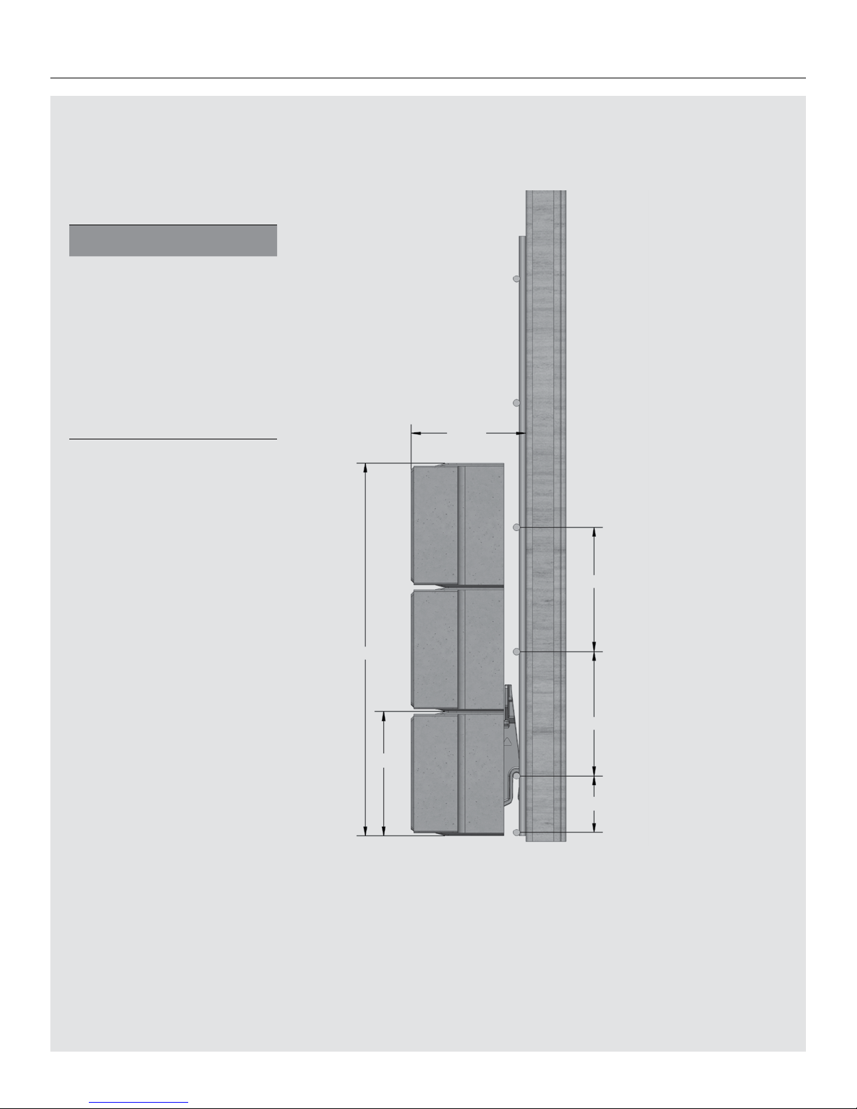
H
83 mm
(3 1/4 in)
90
45
90
90
TYPICAL COMPONENT –
SIDE VIEW
Table – Height of components and its wood frame according
to the modular design of veneer units (90 mm)
# OF ROWS HEIGHT (mm) HEIGHT (in)
2 180 mm 7 1/16
3 270 mm 10 5 /8
4 360 mm 14 3 /16
5 450 mm 17 11/16
6 540 mm 21 1/4
7 630 mm 24 13 /16
8 720 mm 28 1/ 3
9 810 mm 31 1/8
10 900 mm 34 5/8
11 990 mm 39
12 1080 mm 42 1/2
Page 45
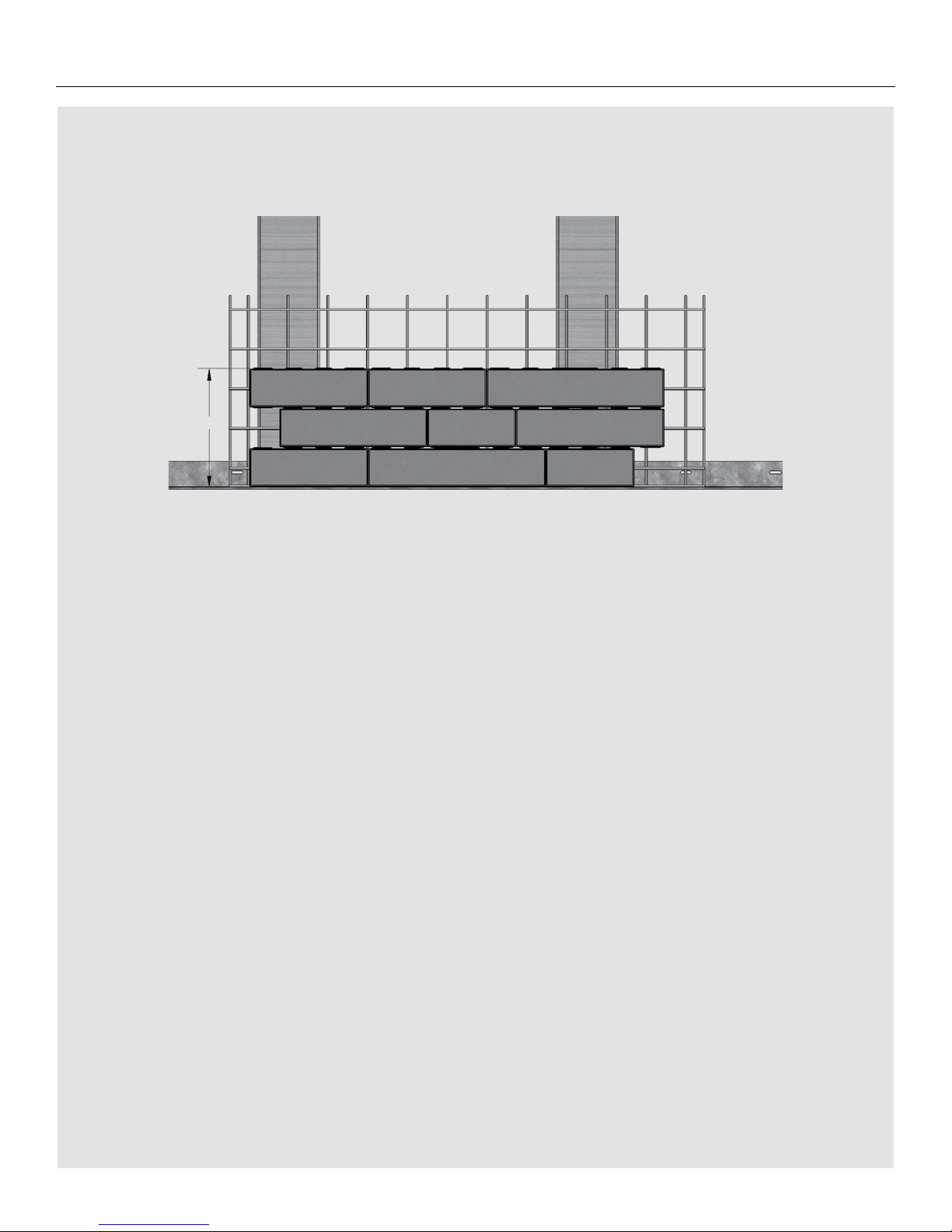
TANDEM® SYSTEM – 45
TYPICAL COMPONENT –
FRONT VIEW
H
CONSTRUCTION OF OUTDOOR LIVING COMPONENTS WITH THE TANDEM MODULAR GRID
Page 46
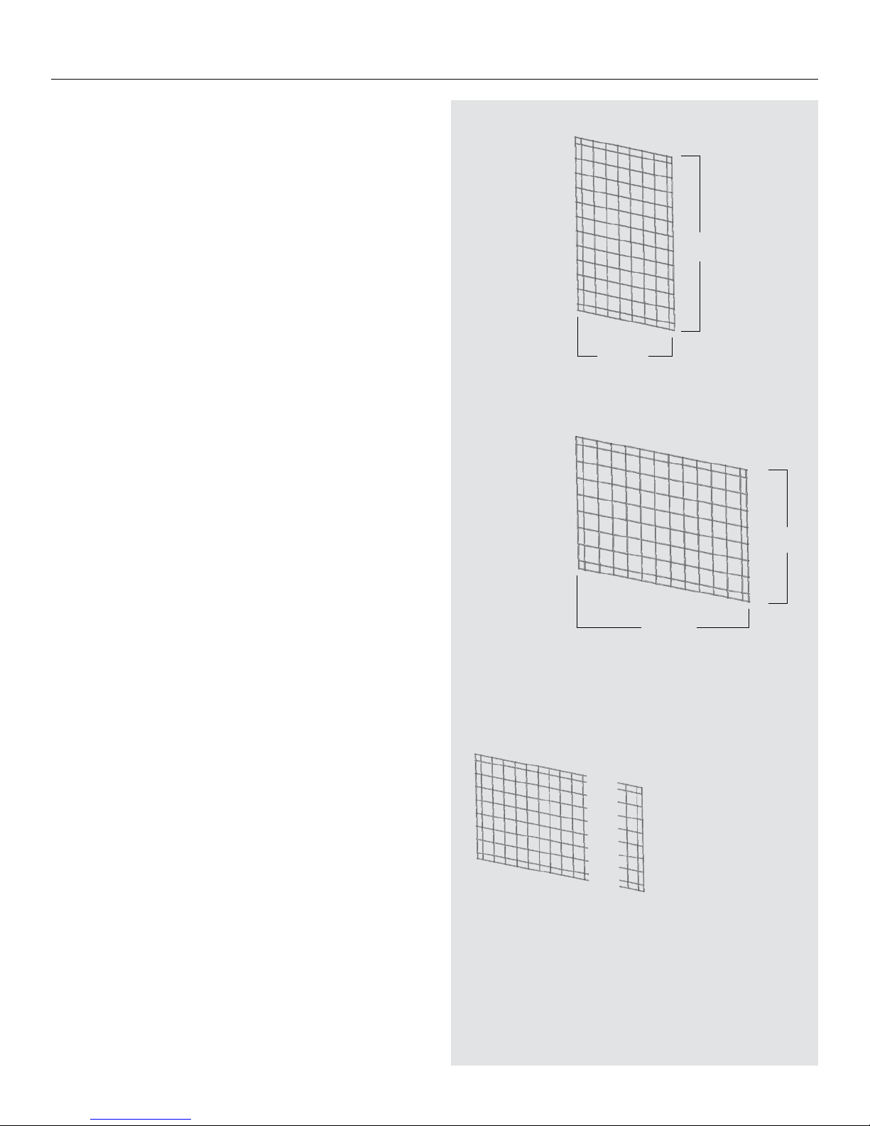
46 – TANDEM® SYSTEM
CONSTRUCTION OF OUTDOOR LIVING COMPONENTS WITH THE TANDEM MODULAR GRID
TANDEM MODULAR GRID
It is important to note that the units to be constructed must always be
straight and have corners (inner and outer) forming a 90° angle. Therefore,
making a corner is a common element in all construction plans. You can
also refer to the plan view detail (page 43) to see how to make a 90°
corner, taking into account the modular design of Tandem veneers and
grids. When building the wood frame, keep in mind that you have to install
Tandem grids. The flexibility of the grid means that you can install it
in either direction, horizontally or vertically.
You have to cut the grids when the unit you’re building is smaller in size
(height or length) than a complete grid of 28" or 42 1/2". It may be helpful
to decide the direction of the grid so as to minimize cuts. To cut a grid,
use any suitable tool like a grinder or bolt cutters.
To avoid making cuts in the veneers, simply follow the dimensions based
on the modular design of the veneers shown in the previous tables.
VERTICAL
INSTA LL ATION
1080 mm
(42 1/2 in)
1080 mm
(42 1/2 in)
720 mm
(28 3/8 in)
720 mm
(28 3/8 in)
HORIZONTAL
INSTA LL ATION
DETAIL 1
Page 47
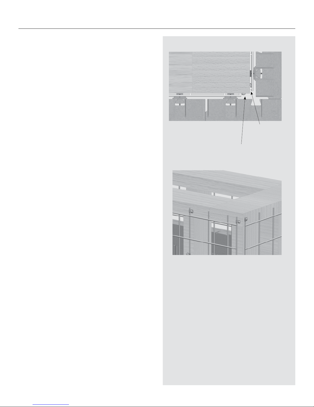
TANDEM® SYSTEM – 47
CONSTRUCTION OF OUTDOOR LIVING COMPONENTS WITH THE TANDEM MODULAR GRID
The grid is attached with the loop clamps and screws supplied. Simply
place the loop clamps around the vertical rods of the grid and then insert a
screw into the wood frame. There are 10 loop clamps per Tandem grid.
To secure a grid, the loop clamps should be evenly positioned, starting with
the edge of the grid and moving towards the center. To ensure the solidity
of the grid, use approximately one fastener (screw and loop clamps) per
square foot of grid or 10 fasteners per square meter. To attach a grid to the
wood frame, the vertical rods must be placed directly against the structure.
Since the metal rods of the grids are spaced every 90 mm, it’s helpful
if the intermediate posts of the wood framing are multiples of 90 mm.
This will increase the available attachment area for the grid. A continuous
attachment area like plywood sheeting can also be used to provide a
larger surface for attaching the Tandem grid.
When a unit requires more than one grid either horizontally or vertically,
they should be installed one after the other in both directions.
CUTTING INSTRUCTION OF
MODULAR GRID (PLAN VIEW)
DETAIL 2
3D VIEW
Keep the last ver tical rod
intact for better fixation
Leave free space to attach
the loop clamps
Page 48
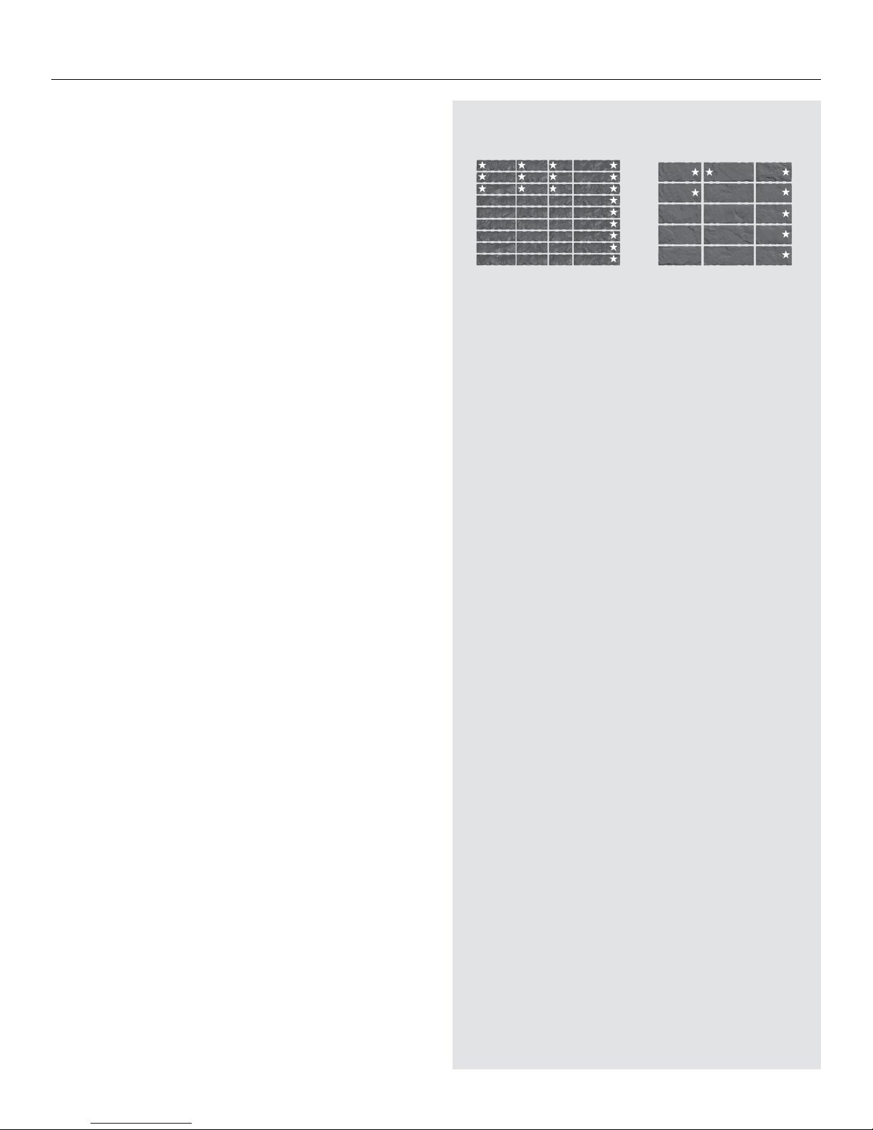
C B A D
F EG
LAFITT TANDEM – 90 mm UNITS LAFITT TANDEM – 180 mm UNITS
STACKING POSITION ON PALLETS (WITH A TE XTURED END)
48 – TANDEM® SYSTEM
CONSTRUCTION OF OUTDOOR LIVING COMPONENTS WITH THE TANDEM MODULAR GRID
TANDEM VENEERS
When the grids have been installed, just insert the veneers for the unit
using the connectors specially designed for the purpose. We recommend
using 2 connectors per veneer for a solid job, but sometimes it can happen
that a connector can’t be inserted because of the grid’s geometry. You can
then secure the veneer by gluing it around other veneers with a concrete
adhesive such as Permapro adhesive.
Normally, for a standard project, all formats of the veneer units are
used randomly. As for retaining walls, always keep in mind the principle
of staggering the vertical joints from one row to another. For the corners,
you need corner units just like constructing a pillar with steel grids
(see “Building Pillars” section). But it should be noted that sometimes
the construction of a short unit requires a larger quantity of the same
format veneers, especially corner units (the quantity of corner units
supplied comes to approximately one-third of a pallet). It is important
to check this when calculating the quantity so as to have enough of
the appropriate veneers on hand.
It is also possible to use 180 mm veneers when constructing a unit,
the same as for a retaining wall or a column.
Page 49
TANDEM® SYSTEM – 49
CONSTRUCTION OF OUTDOOR LIVING COMPONENTS WITH THE TANDEM MODULAR GRID
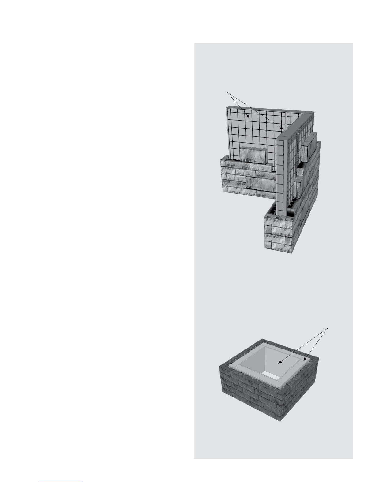
BRACING
Some items require bracing panels like plywood sheeting, especially
for privacy walls, fencing and deck skirting. These panels are needed
to strengthen the unit to withstand stress such as wind and to limit
distortion under regular loads.
Other units require the installation of fiber cement panels for
heat insulation (barbecues and outdoor gas fireplaces) or as protection
against moisture (flower boxes). In these situations, we recommend
fiber cement panels of a minimum thickness of 12 mm (1/2").
EXAMPLE OF A HEAT PROTECTION SET-UP
EXAMPLE OF BRACING
(PRIVACY WALL)
Plywood sheeting
for bracing
Fiber cement panel for
protection against heat
Page 50
50 – TANDEM® SYSTEM
CONSTRUCTION OF OUTDOOR LIVING COMPONENTS WITH THE TANDEM MODULAR GRID
Note: When a section of a unit has veneers that are not directly supported on the ground
(foundation modules, pavers or concrete slabs), for example for installing doors, the veneers
must be supported on shelf angle sections attached to the wood frame.
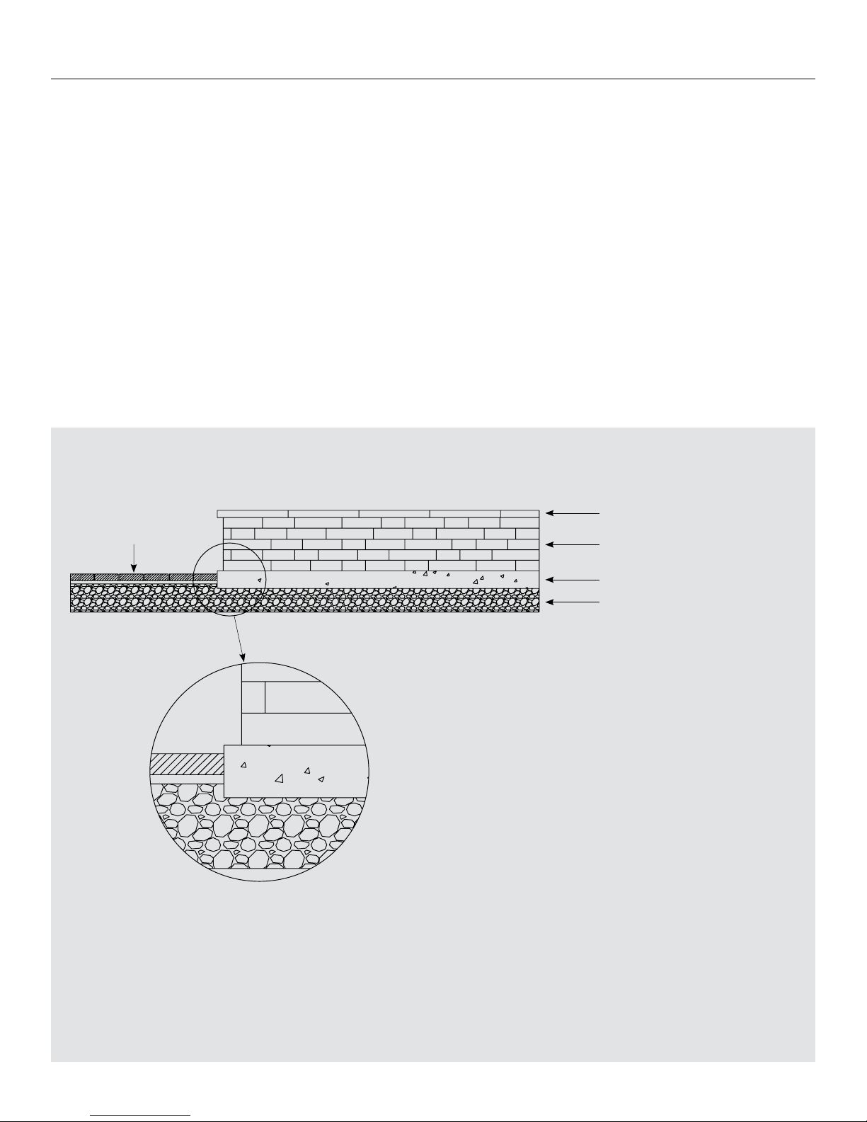
BASE SUPPORT FOR OUTDOOR UNITS
Outdoor units like a bench, flower box or outdoor fireplace can
usually be built on a base of concrete foundation (starter modules)
or placed directly onto concrete pavers. A granular base of compacted
crushed stone should be laid before the foundation. However, we
recommend that long or heavy units be supported on a concrete slab
(minimum thickness of 150 mm or 6"). We also recommend that units
like barbecues or tables with a single granite, quartz or marble top over
their entire surface be supported on a reinforced concrete slab to prevent
the top from breaking if the ground shifts. In each case, a compacted
granular base should underlie the concrete slab.
COMPONENTS SUPPORTED
ON A CONCRET SLABS – CROSS SECTION
Tandem capping unit
Concrete pavers
Tandem veneer units
(with modular grid)
Concrete slab 150 mm (6 in)
Granular foundation
Page 51

TANDEM® SYSTEM – 51
CONSTRUCTION OF OUTDOOR LIVING COMPONENTS WITH THE TANDEM MODULAR GRID
CONSTRUCTION LUMBER
Building the different units in this guide requires construction lumber
for the framing: 2 × 4, 2 × 6 and 2 × 8 boards, 4 × 4 and 6 × 6 posts
and plywood sheets. We recommend that all wood used outdoors be
treated against rot according to established procedures approved by Health
Canada. You should use S-P-F #1 or #2 wood, or better. This type of wood
usually has a minimum life of 15 years without maintenance in normal
outdoor conditions.
Note : Wooden components that have been cut or sawed
should be treated with an anti-rot product.
COMPLIANCE WITH CONSTRUCTION STANDARDS
In all circumstances, units to be constructed must always comply
with the requirements of the National Building Code (version specific
to your region) and local municipal bylaws and regulations.
Page 52
52 – TANDEM® SYSTEM
CONSTRUCTION OF OUTDOOR
LIVING COMPONENTS WITH
THE TANDEM MODULAR GRID
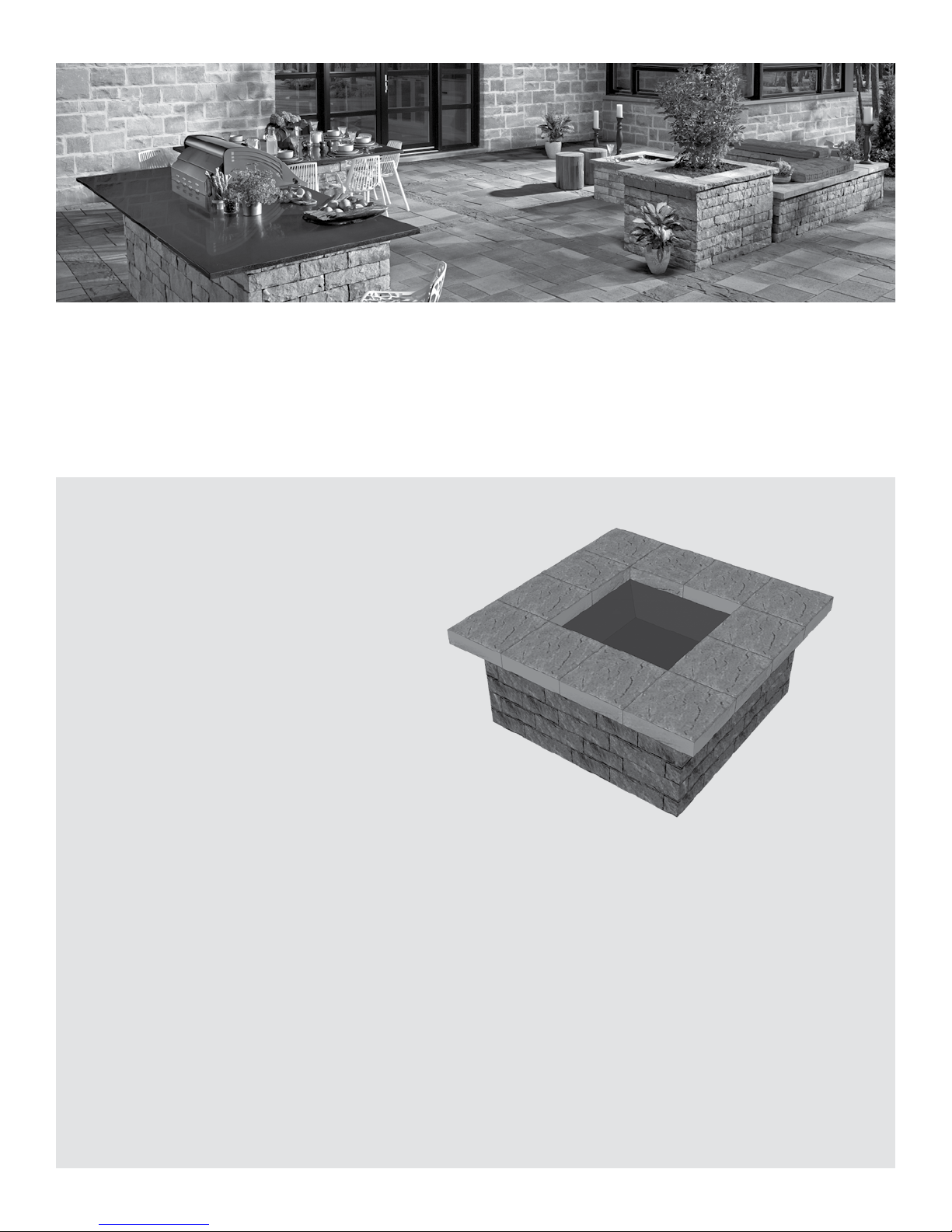
BUILDING AN OUTDOOR GAS FIREPLACE
Note that the only type of fireplace recommended for
this type of construction is a propane gas or natural gas fireplace.
A wood fireplace is not permitted.
Construction should begin with laying a solid foundation
that is leveled, compacted and well drained.
The wood framing must be built according to the type of
fireplace chosen. Dimensions are calculated using the data on
shop drawings provided by the fireplace manufacturer. It may be
necessary to add some extra parts like plywood shims for adjusting
to the exact modular dimensions of the fireplace (Tandem modular
veneers according to the wood frame design).
It is essential to install heat insulation. A fiber cement panel of a
minimum thickness of 12 mm (1/2" ) is recommended for adequate protection.
The panels must be installed all around the heating element (burner).
You must also plan to install conduits in the ground for gas pipes
and for electric cables if required.
Page 53
TANDEM® SYSTEM – 53
CONSTRUCTION OF OUTDOOR LIVING COMPONENTS WITH THE TANDEM MODULAR GRID
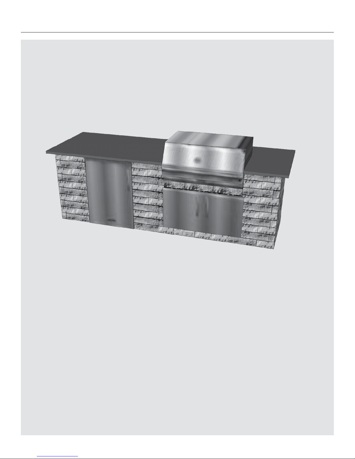
BUILDING AN OUTDOOR KITCHEN
(BARBECUE, REFRIGERATOR, BAR)
The wood frame must be constructed according to the type of barbecue chosen.
Dimensions are calculated using data on the shop drawings provided by the barbecue
manufacturer. Additional accessories such as a fridge or integrated cabinet doors are
also possible. Naturally, you have to plan on adding pieces of wood to attach accessories
to the wooden structure, like a frame in the case of doors. When purchasing supplies,
you will usually find moldings to finish the edges of the various units.
It is essential to install protection from heat and sparks. A fiber cement panel
of a minimum thickness of 12 mm (1/2") or a double-skinned steel section if provided
by the BBQ manufacturer is recommended for adequate protection. The panels must
be installed all around the heating element (burner).
Finish off with concrete coping or panels of granite, quartz, marble or natural stone.
The panels must be made to measure by specialized companies. You must make special
provisions for handling and installation to avoid possible breakage. The panels are
attached on top of the plywood with silicone adhesive to prevent movement.
Provide adequate means for venting gases when constructing the barbecue.
(Refer to the barbecue manufacturer's recommendations for the position and
size of the ventilation grid required).
You should also plan to install conduits for gas pipes and electric cables.
The conduits may in certain cases be installed in the ground.
Page 54
54 – TANDEM® SYSTEM
CONSTRUCTION OF OUTDOOR LIVING COMPONENTS WITH THE TANDEM MODULAR GRID
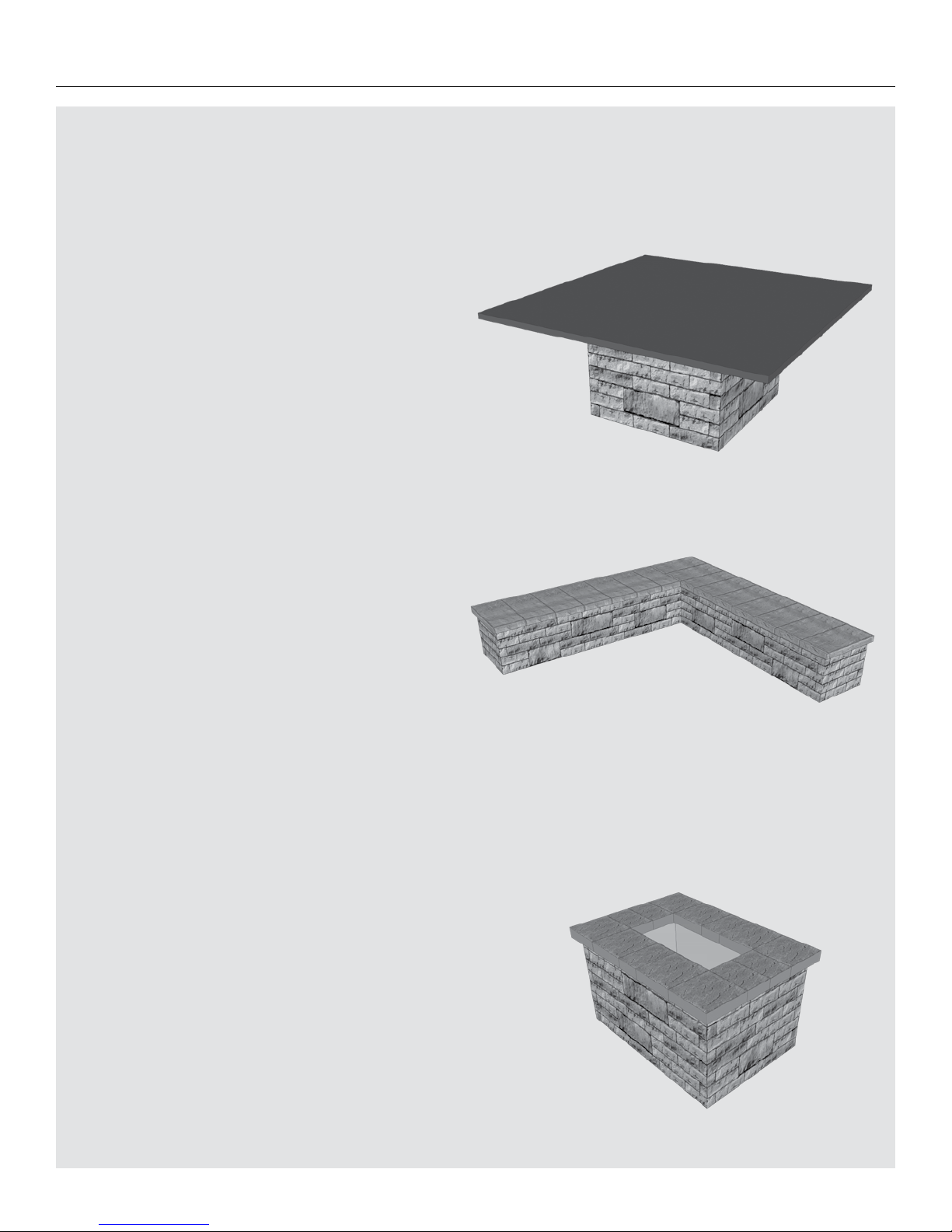
BUILDING PATIO FURNITURE
(TABLE AND BENCH) AND FLOWER BOX
TABLE
You can make a table by building a Tandem unit (grid and veneers) to form
the base and then adding a tabletop. The tabletop can be wood, granite, quartz,
marble or natural stone.
Dimensions may vary. It is essential to leave a minimum space between the table edge
and the base. At least 460 mm (18") is needed for leg room.
Granite, quartz or marble tabletop: the tabletop must be attached to the veneers
with a silicone adhesive. We recommend that a tabletop resting on a Tandem unit
be made from a single piece to increase rigidity and stability. This allows you to avoid
adding a metal fastener to secure the tabletop to the structure for increased stability
and extra protection where necessary. For very large tabletops, it is recommended
to install steel supports (angles) to better stabilize the whole unit. You should enquire
from the tabletop supplier what are the optimal sizes and thicknesses for stability
and security and to avoid possible breakage.
BENCH
You can make a bench by building a structure for the base and simply adding
a concrete coping unit for the seat. Bench dimensions can vary, but it may be helpful
to make your decision based on available coping units in order to avoid cuts.
For a typical bench, the coping will be of the Melville Tandem type.
FLOWER BOX
It is recommended to install a fiber cement panel and a geotextile membrane to protect
the wood against deterioration caused by vegetable and mineral materials (plants and soil).
You should provide water drainage when building the structure.
For the coping, use the following Permacon capping products for retaining walls:
Mondrian capping module 50 mm, Lafitt, Melville and Esplanade capping modules.
Page 55
TANDEM® SYSTEM – 55
CONSTRUCTION OF OUTDOOR LIVING COMPONENTS WITH THE TANDEM MODULAR GRID
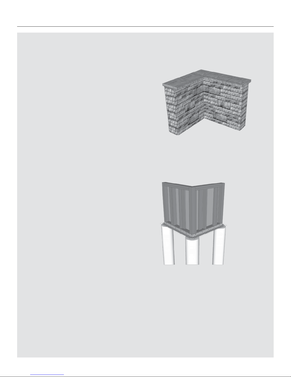
BUILDING PRIVACY WALLS AND FENCES
When you’re building a fence or when you want to hide or conceal various
pieces of equipment (e.g. pool filter, heat pump) or utility items (e.g. trashcans
or storage bins), the Tandem modular grid system is just what you need.
Fencing is mostly built with treated wood posts (structural, select quality) supported
by cast-in-place concrete foundations (Sonotubes) for the main structure. An intermediate
structure in treated wood boards is then installed between the posts to attach the fence
components of Tandem modular grids and veneers. A shelf angle is fixed to the base of
the structure to provide continuous support for the weight of the veneers. The shelf angle
(2 1/2" × 2 1/2" × 8' ) is attached to the base of the structure (wood poles and boards
forming the stringer) with suitable screws (#10 x 3 1/2" ) every 200 mm (8"). This shelf
angle can be cut to the size of the unit under construction.
The wooden structure between the posts, combined with the shelf angle, supports
the weight of the walls and transfers it to the foundations. Fences and privacy walls
must rest on pillars (Sonotubes) and concrete foundations to transfer the weight of
the walls to the ground. The foundations are also necessary to prevent the walls
from collapsing due to the force of the wind.
The dimensions of the foundations in this guide were calculated to respect the
weight-bearing capacity of the soil and to limit irregular subsidence that could lead
to distortions in the wall. Calculations were made for soil conditions of low weight-bearing
capacity. For different soil conditions, we recommend consulting a qualified engineer.
The foundation must be built to withstand local frost conditions. The depth of frost in this
guide is 1.8 m (6'). The use of screw piles is not recommended for this type of application.
Privacy walls are made with the same main structure to which
a perpendicular section is added to obscure non-aesthetic items.
The maximum height of a fence or a privacy wall is limited to 1.8 m (6 ft).
The maximum length of a wall facade between posts is 2.4 m (8 ft).
The unit can be built to display its aesthetic appearance on one side
or both sides simultaneously.
The wood frame must integrate a bracing panel such as a sheet of 12 mm (1/2")
treated plywood to provide a continuous attachment area and stabilize the structure
to withstand loads. To finish the walls, attach a cap on top of the wood frame, either
in concrete (sizes to be decided on site) or metal (custom bent by a specialized company).
Esplanade coping and Tandem Melville steps can be used to finish the top of a fence
or privacy wall.
The capping unit is fixed with a suitable concrete adhesive spread on the wooden
structure and the top of veneers. It may be useful to fix the wooden structure
to the concrete cap with a metal attachment to provide additional wind protection.
PRIVACY WALL
PRIVACY WALL ON CONCRETE
PILLAR (SONOTUBE) – CONSTRUCTION
DETAILS OF WOODEN STRUCTURE
Page 56
56 – TANDEM® SYSTEM
CONSTRUCTION OF OUTDOOR LIVING COMPONENTS WITH THE TANDEM MODULAR GRID
Since unit components will vary according to height from zero to 1.8 m (6'),
we present the main minimum requirements in table form.
DESIGN DATA FOR FENCES
Fence with veneer on one side
HEIGHT Ø PILASTER FOOTING EMBEDDING POST POST STRUCTURE
0 to 4 ft – Option 1 12 in / 300 mm Ø 24 in / 600 mm 24 in / 600 mm 4 × 4* 2 × 4
0 to 4 ft – Option 2 12 in / 300 mm 16 in × 16 in / 400 mm × 400 mm 24 in / 600 mm 4 × 4* 2 × 4
0 to 4 ft – Option 3 24 in / 600 mm N/A 24 in / 600 mm 4 × 4* 2 × 4
4 to 5 ft – Option 1 12 in / 300 mm Ø 24 in / 600 mm 24 in / 600 mm 6 × 6** 2 × 6
4 to 5 ft – Option 2 12 in / 300 mm 16 in × 16 in / 400 mm × 400 mm 24 in / 600 mm 6 × 6** 2 × 6
5 to 6 ft – Option 1 12 in / 300 mm Ø 24 in / 600 mm 24 in / 600 mm 6 × 6** 2 × 6
5 to 6 ft – Option 2 12 in / 300 mm 20 in × 20 in / 500 mm × 500 mm 24 in / 600 mm 6 × 6** 2 × 6
Fence with veneer on both sides
HEIGHT Ø PILASTER FOOTING EMBEDDING POST POST STRUCTURE
0 to 4 ft – Option 1 12 in / 300 mm Ø 24 in / 600 mm 24 in / 600 mm 4 × 4* 2 × 4
0 to 4 ft – Option 2 12 in / 300 mm 20 in × 20 in / 500 mm × 500 mm 24 in / 600 mm 4 × 4* 2 × 4
4 to 5 ft – Option 1 12 in / 300 mm Ø 24 in / 600 mm 24 in / 600 mm 6 × 6** 2 × 6
4 to 5 ft – Option 2 12 in / 300 mm 20 in × 20 in / 500 mm × 500 mm 24 in / 600 mm 6 × 6** 2 × 6
5 to 6 ft – Option 1 12 in / 300 mm Ø 24 in / 600 mm 24 in / 600 mm 6 × 6** 2 × 6
5 to 6 ft – Option 2 12 in / 300 mm 22 in × 22 in / 550 mm × 550 mm 24 in / 600 mm 6 × 6** 2 × 6
DESIGN DATA FOR PRIVACY WALLS
Wall with veneer on one side
HEIGHT Ø PILASTER FOOTING EMBEDDING POST POST STRUCTURE
L1 and L2 Configuration = 1.2 m (4 ft)
0 to 3 ft 16 in / 400 mm N/A 24 in / 600 mm 4 × 4* 2 × 4
3 to 6 ft – Option 1 24 in / 600 mm N/A 24 in / 600 mm 6 × 6 2 × 6
3 to 6 ft – Option 2 12 in / 300 mm 16 in × 16 in / 400 mm × 400 mm 24 in / 600 mm 6 × 6 2 × 6
3 to 6 ft – Option 3 12 in / 300 mm Ø 24 in / 600 mm 24 in / 600 mm 6 × 6 2 × 6
L1 Configuration = 2.4 m (8 ft) and L2 = 1.2 m (4 ft)
0 to 4 ft – Option 1 24 in / 600 mm N/A 24 in / 600 mm 4 × 4* 2 × 4
0 to 4 ft – Option 2 12 in / 300 mm 16 in × 16 in / 400 mm × 400 mm 24 in / 600 mm 4 × 4* 2 × 4
4 to 5 ft – Option 1 24 in / 600 mm N/A 24 in / 600 mm 6 × 6** 2 × 6
4 to 5 ft – Option 2 12 in / 300 mm 16 in × 16 in / 400 mm × 400 mm 24 in / 600 mm 6 × 6** 2 × 6
4 to 5 ft – Option 3 12 in / 300 mm Ø 24 in / 600 mm 24 in / 600 mm 6 × 6** 2 × 6
5 to 6 ft – Option 1 12 in / 300 mm 16 in × 16 in / 400 mm × 400 mm 24 in / 600 mm 6 × 6** 2 × 6
5 to 6 ft – Option 2 12 in / 300 mm Ø 24 in / 600 mm 24 in / 600 mm 6 × 6** 2 × 6
Wall with veneer on both sides
HEIGHT Ø PILASTER FOOTING EMBEDDING POST POST STRUCTURE
L1 and L2 Configuration = 1.2 m (4 ft)
0 to 4 ft 16 in / 400 mm N/A 24 in / 600 mm 4 × 4* 2 × 4
4 to 6 ft – Option 1 12 in / 300 mm 16 in × 16 in / 400 mm × 400 mm 24 in / 600 mm 6 × 6** 2 × 6
4 to 6 ft – Option 2 12 in / 300 mm Ø 24 in / 600 mm 24 in / 600 mm 6 × 6** 2 × 6
L1 Configuration = 2.4 m (8 ft) and L2 = 1.2 m (4 ft)
0 to 3 ft 24 in / 600 mm N/A 24 in / 600 mm 4 × 4* 2 × 4
3 to 4 ft – Option 1 12 in / 300 mm 16 in × 16 in / 400 mm × 400 mm 24 in / 600 mm 4 × 4* 2 × 4
3 to 4 ft – Option 2 12 in / 300 mm Ø 24 in / 600 mm 24 in / 600 mm 4 × 4* 2 × 4
4 to 6 ft – Option 1 12 in / 300 mm 20 in × 20 in / 500 mm × 500 mm 24 in / 600 mm 6 × 6** 2 × 6
4 to 6 ft – Option 2 12 in / 300 mm Ø 24 in / 600 mm 24 in / 600 mm 6 × 6** 2 × 6
N/A : Not Applicable *
4 × 4 SFP Wood Select Structural
**
6 × 6 #1 SFP Wood
It should be noted that the base of concrete pillars should normally have a wider section in the ground for a footing. The footing can take two shapes,
square or round. There are round footings on the market, sold as Bigfoot, which can be used for the construction of pillars. Square footings must be
made on site with wooden formwork.
PLAN VIEW
L1
L2
Page 57

TANDEM® SYSTEM – 57
CONSTRUCTION OF OUTDOOR LIVING COMPONENTS WITH THE TANDEM MODULAR GRID
DESIGN ASSUMPTIONS
The construction of privacy walls or fences
must take into account the following assumptions:
Wall weight (grid and veneers): 28 lbs/sq f t (1.35 kN/m²)
Wind: 20 lbs/sq ft (1 kPa)
Minimum allowable bearing capacity of soil: 1,575 lbs/sq ft (75 kPa)
Density of soil around pillars and foundations (y): 112 lbs/cu ft (18 kN/ m³)
Backfill must be compacted around Sonotubes and spread footings
Minimum depth of foundations: 6 ft (1.8 m) away from frost
(consult an engineer to check the typical depth of frost for your area)
Note: Design assumptions do not take into account ear thquake effects.
It may be necessary to consult an engineer.
Leave a free space under the Tandem wall of at least 75 mm (3")
to ensure proper ventilation and adequate room for the potential effects
of freezing and thawing.
Page 58
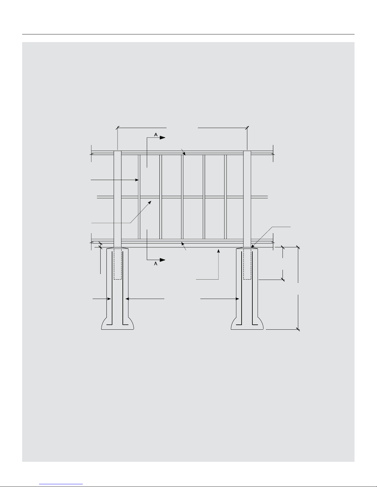
2400 mm max
(8 ft)
2-2
× 4 or 2–2 × 6
4 × 4 or 6 × 6
4 × 4 or 6 × 6
2 × 4 or 2 × 6
at 400 mm (16 in) c/c
Sonotube
Ø 300 mm (12 in)
Finish the concrete
with a drainage slope
Girth at mid-height
if H>1370 mm (4 ft 6 in)
2-2
× 4 or 2–2 × 6
Minimum reinforcement
4-15 M
Finished grade
Variable height
(see table of design data)
1.8 m
(6 ft)
75 mm
(3 in)
Footing
(see table of design data)
600 mm
(24 in)
58 – TANDEM® SYSTEM
CONSTRUCTION OF OUTDOOR LIVING COMPONENTS WITH THE TANDEM MODULAR GRID
Note : The details shown here are only valid for the application suggested in
this guide, taking into account the prescribed limitations. You are strongly
recommended to engage a structural engineer or specialist in the field
to validate structural design details for other configurations or for different soil
conditions (lower or higher load capacity, presence of blocks, support on rock, etc.).
PRIVACY WALLS AND FENCES –
TYPICAL FRONT VIEW
Page 59
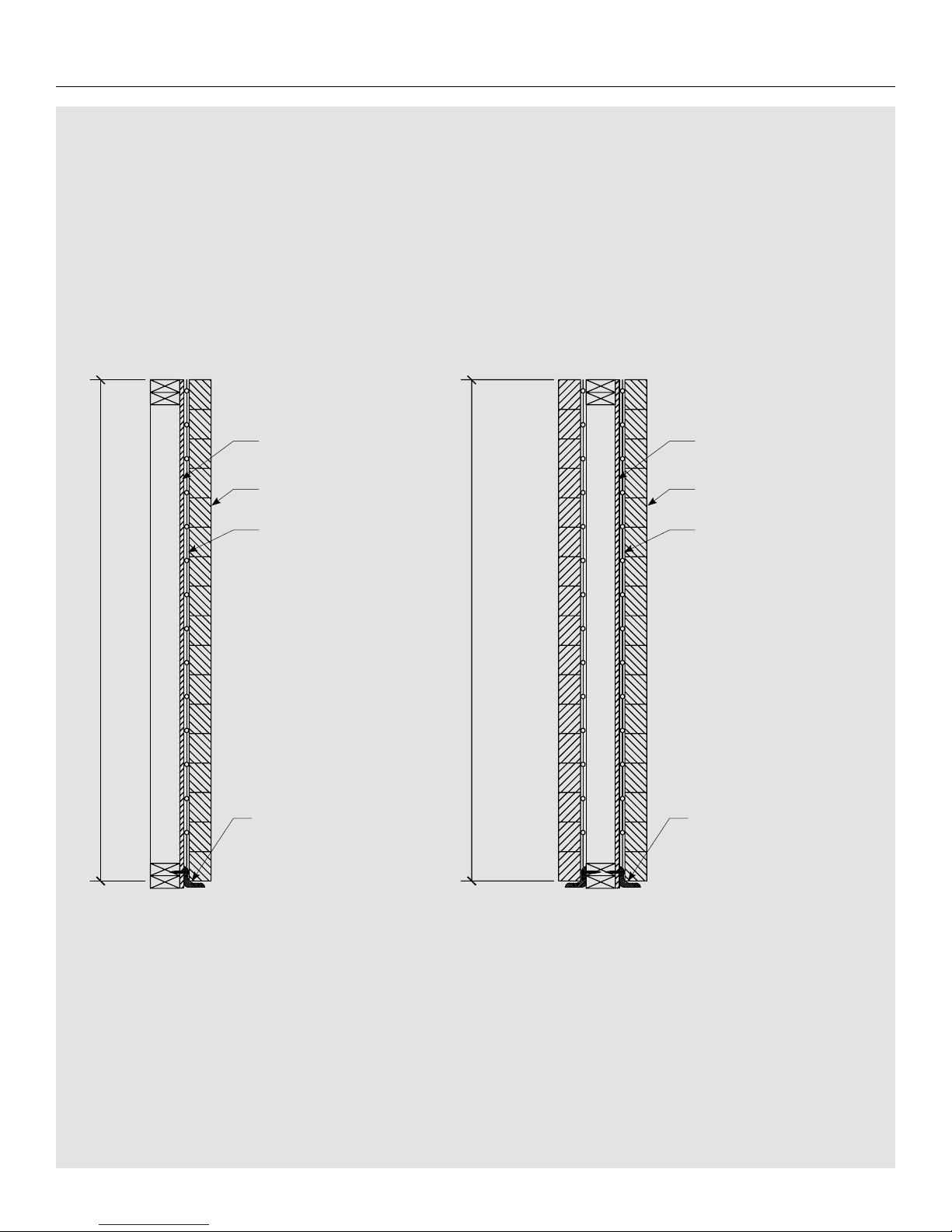
VARIABLE HEIGHT (SEE TABLE)
VARIABLE HEIGHT (SEE TABLE)
2 × 4 OR 2 × 6 @ 400 mm (16 in) c/c
2
× 4 ou 2 × 6 @ 400 mm (16 po) c/c
TANDEM® SYSTEM – 59
CONSTRUCTION OF OUTDOOR LIVING COMPONENTS WITH THE TANDEM MODULAR GRID
PRIVACY WALLS AND FENCES –
CROSS-SECTION A-A
ONE-SIDED DOUBLE-SIDED
Treated plywood 12 mm (1/2 in)
Tandem veneer
Tandem gr id
Shelf angle
64
× 64 × 2439 × 4 mm
(
2 1/2" × 2 1/2" × 8' min 10 gauge)
#10 Screw × 3 1/2" in long at 20 0 mm (8 in) c/c
Stainless Steel
Shelf angle
64 × 64 × 2439 × 4 mm
(
2 1/2" × 2 1/2" × 8' min 10 gauge)
#10 Screw × 3 1/2" in long at 20 0 mm (8 in) c/c
Stainless Steel
Treated plywood 12 mm (1/2 in)
Tandem veneer
Tandem gr id
Page 60
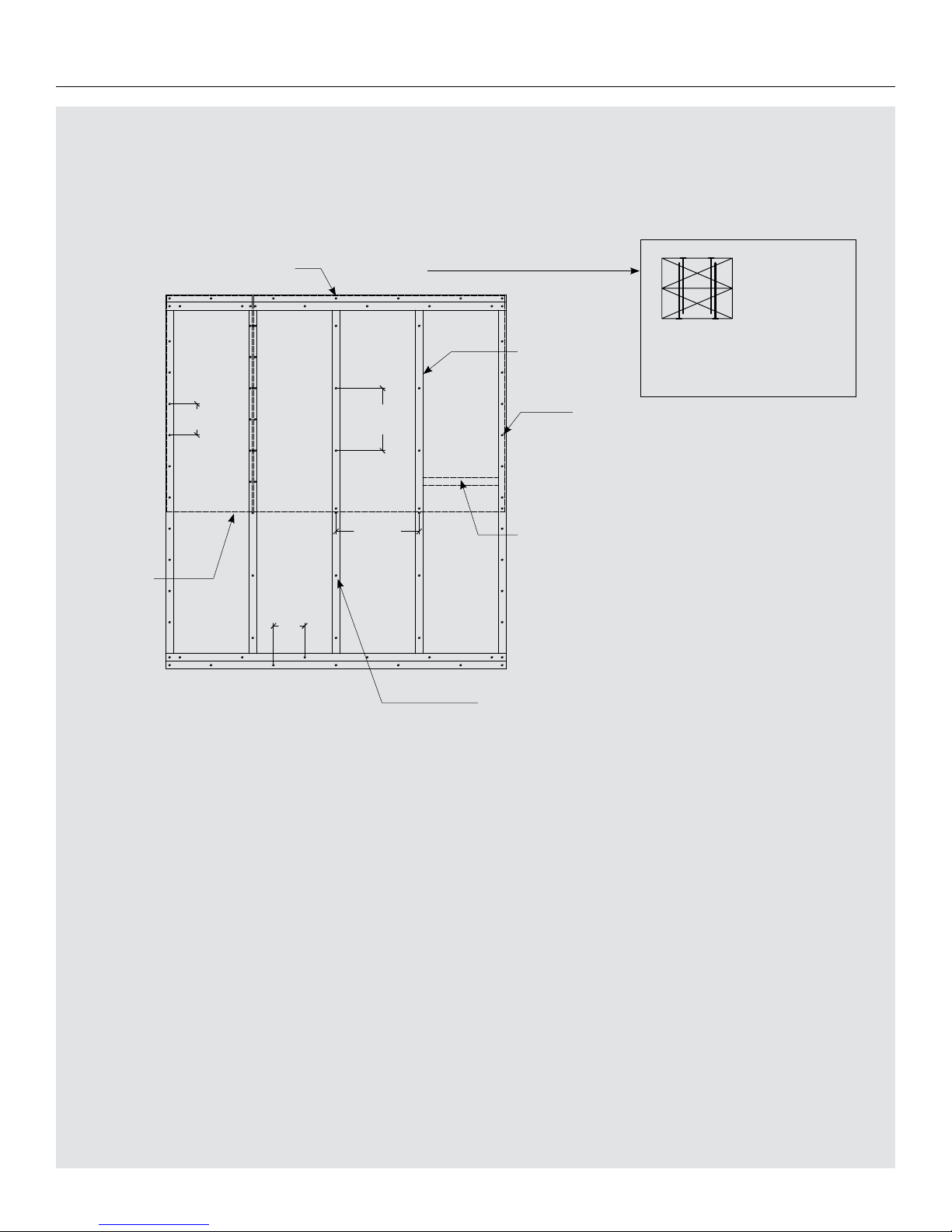
60 – TANDEM® SYSTEM
CONSTRUCTION OF OUTDOOR LIVING COMPONENTS WITH THE TANDEM MODULAR GRID
SCREW DIAGRAM OF COMPONENTS
OF WOODEN STRUCTURE
ASSEMBLY 2-2 × 4 OR 2-2 × 6
WITH #10 SCREW × 3 1/2 in LONG
STAGGERED
Double rail (2 × 2 × 4 or 2 × 2 × 6)
screwed together at 200 mm (8 in) c/c
2 #10 screw × 3 1/2 in
for vertical post
Plywood sheet
(see note)
2 × 4 or 2 × 6
at 400 mm (16 in) c/c
#10 screw × 1-1/2 in
at 6 in c/c
at the perimeter
Girth at mid-height if
H>1370 mm (4 ft 6 in)
Note: Leave a space of 2-3 mm (1/8 in)
between plywood sheets
#10 screw × 1-1/2 in @ 12 in c/c
150 mm
(6 in)
6 in
300 mm
(12 in)
400 mm
(16 in )
Page 61
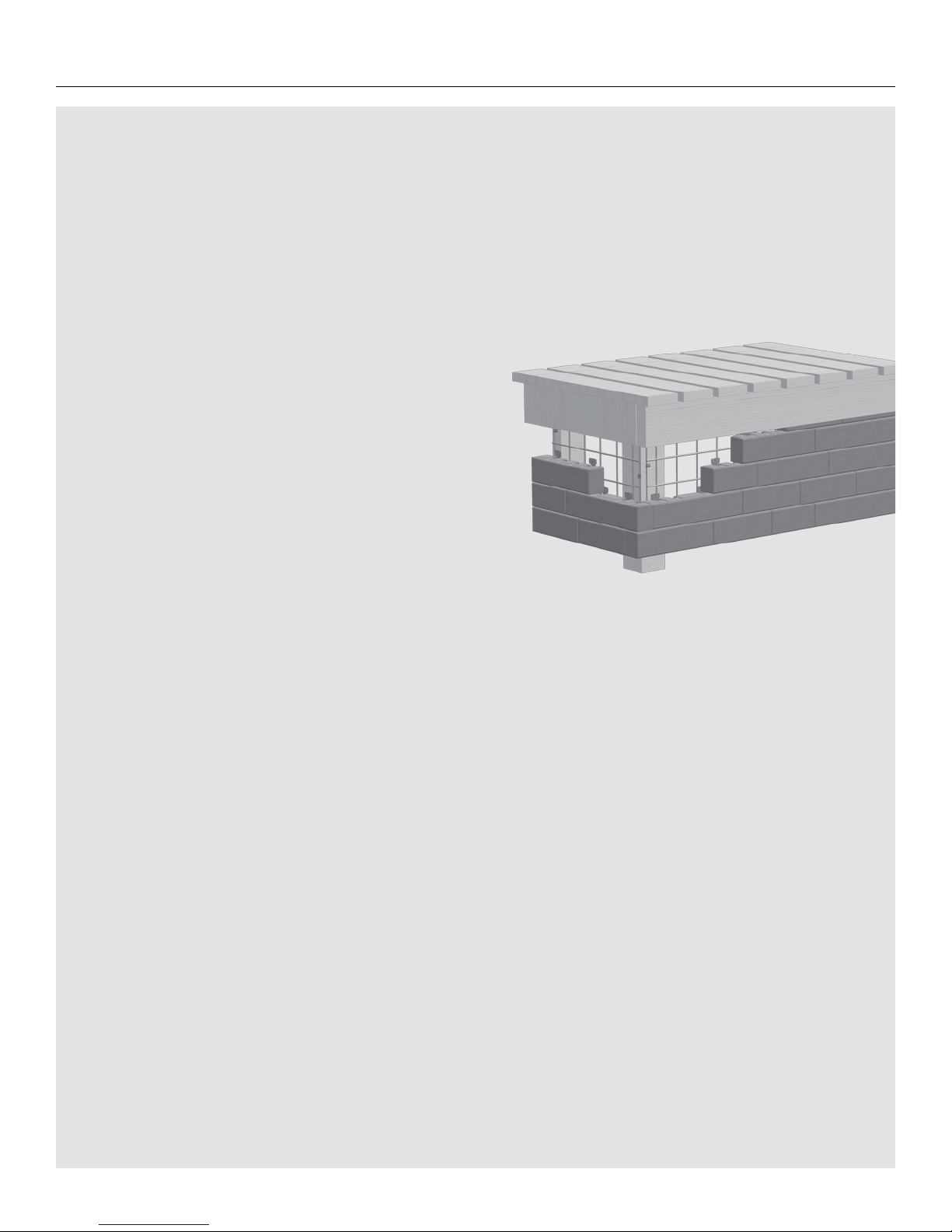
TANDEM® SYSTEM – 61
CONSTRUCTION OF OUTDOOR LIVING COMPONENTS WITH THE TANDEM MODULAR GRID
BUILDING DECK SKIRTING
Applications: new wood or concrete decks,
or existing concrete decks
Another application of the Tandem grid consists of covering the free space
under a deck by building a Tandem wall around it. Tandem veneers are supported
by a galvanized shelf angle and a wood frame fixed to the deck (wood or concrete).
The wood frame consists of treated plywood to provide a continuous attachment area
for the grid, and ver tical bracing to stabilize the structure and withstand lateral
loads such as the wind. The whole structure is supported by appropriate foundations
(screw piles for wooden decks and concrete foundations for concrete decks).
Maximum height of Tandem wall: 1.5 m (5 ft)
To install deck skirting on existing concrete structures, you must first ensure
that the initial structure (the deck itself) can bear the additional weight of new
covering components: wooden structure, shelf angle and Tandem veneers.
For this kind of project, it is strongly recommended to engage a structural engineer
or specialist in the field to validate the structural design details for adequate
load bearing.
In all cases, it is necessary to minimally comply
with the design criteria shown below:
Wall weight (grid and veneers): 1.35 KN /m² (28 lbs /sq ft)
Wind: 1 kPa (21 lbs /sq ft)
Overload : 1.9 kPa (40 lbs/sq ft)
Note: Design assumptions do not take into account earthquake effects.
It may be necessary to consult an engineer.
Minimum allowable bearing capacity of soil: 75 kPa (1575 lbs/sqft).
Minimum depth of foundations in soil: 1.8 m (6 ft) away from frost
(consult an engineer to check the typical depth of frost for your area).
Leave a free space under the Tandem wall of at least 75 mm (3").
Note: As there is no direct access from the top of a unit (since the Tandem wall
is built under the deck), it will be impossible to attach the last row of veneers
to the Tandem grid with connectors. Simply glue the last row of veneers to the
second-to-last row with a concrete adhesive like Permapro adhesive.
The sketches shown here have been designed to withstand the additional loads of
Tandem walls. The details shown are valid for applications suggested in this guide.
It is strongly recommended to engage a structural engineer or specialist in the field
to validate structural design details for other configurations.
DECK SKIRTING –
3D VIEW
Page 62
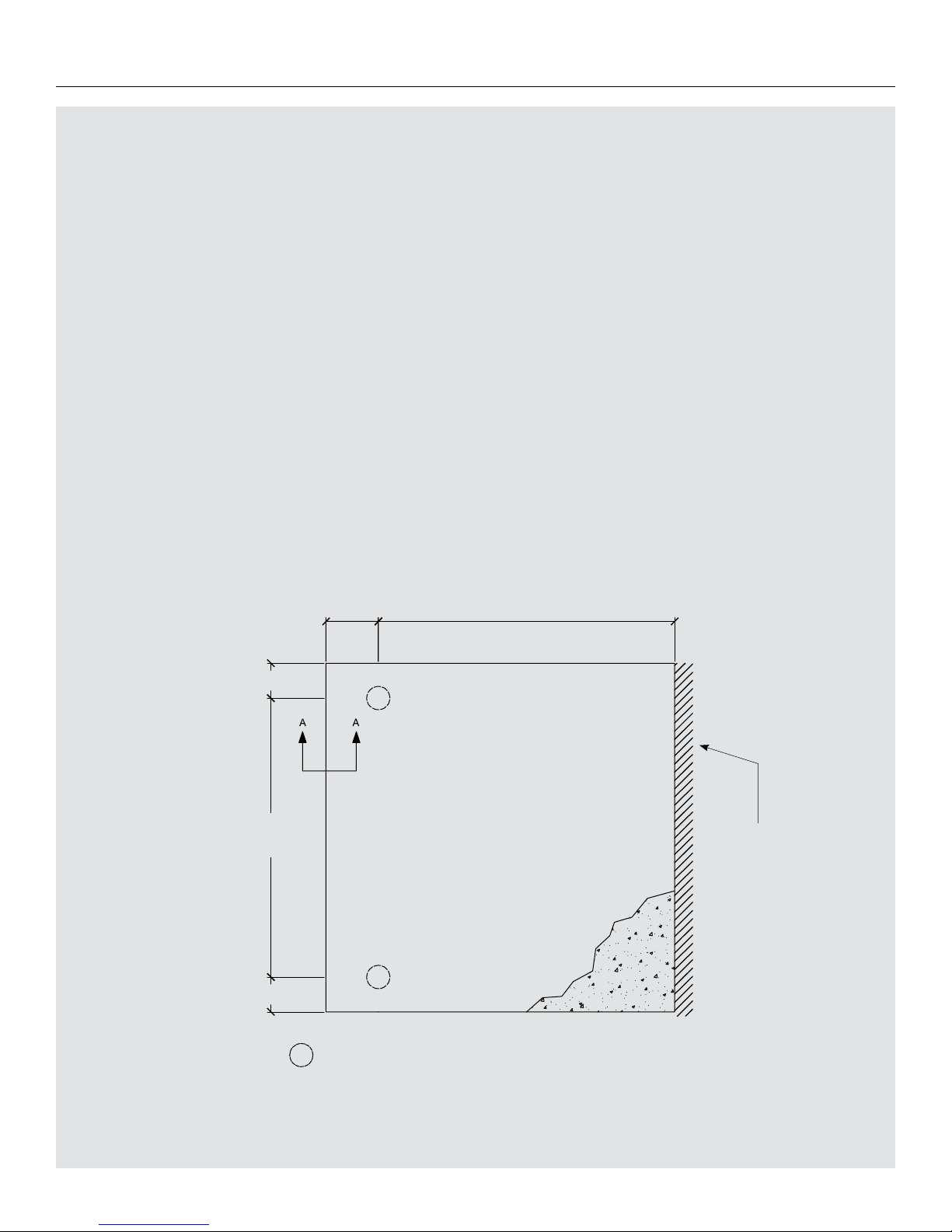
62 – TANDEM® SYSTEM
CONSTRUCTION OF OUTDOOR LIVING COMPONENTS WITH THE TANDEM MODULAR GRID
CONCRETE DECK
To cover a concrete deck, you must comply with
additional minimum design criteria detailed below:
The minimum thickness of the slab should be 140 mm (5 1/2" )
The slab should be reinforced with a minimum 10M reinforcement
at 300 mm (12") c / c in both directions and positioned at the center
of the slab. The concrete deck should be suppor ted by pillars of
reinforced concrete (Sonotubes), 200 mm (8") in diameter with
a minimum footing of 600 mm (24" ) or larger in diameter.
The compressive strength of the concrete (slab and pillars)
must be at least 30 MPa with 5% to 8% entrained air.
Maximum distance between pillars: 2400 mm (8 ft)
Maximum overhang of concrete slab: 600 mm (2 ft)
To attach the components of the wooden structure to the concrete slab,
you should use mechanical anchors like Hilti Kwik Bolt TZ
(12 mm diameter by 140 mm long) or equivalent (not supplied by Permacon).
Leave a space of at least 12 mm (1/2" ) between the top
of the Tandem wall and the underside of the concrete slab.
CONCRETE DECK SKIRTING –
PLAN VIEW
2.4 m
(8 ft)
300 mm
(1 ft)
300 mm
(1 ft)
Post
Ø 200 mm (8 in)
450 mm
(1 ft 6 in)
2.55 m
(8 ft 6 in)
Concrete foundation wall
Concrete slab
140 mm (5 1/2 in)
minimum thickness
Page 63
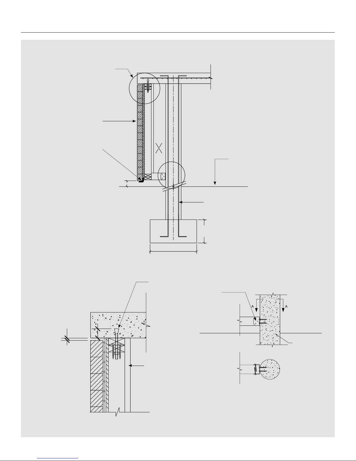
TANDEM® SYSTEM – 63
CONSTRUCTION OF OUTDOOR LIVING COMPONENTS WITH THE TANDEM MODULAR GRID
CONCRETE DECK SKIRTING –
CROSS-SECTION A-A
DETAIL 1 DETAIL 2
DETAIL 1
Tandem wall (with grid)
Shelf angle
Reinforcement 4 – 15M
Finished grade
300 mm
(12 in)
Square or round spread
footing Ø 600 mm (24 in)
600 mm
× 600 mm
Minimum 76 mm (3 in) clearance
50 mm
(2 in)
* Diagonal bracing
2
× 4 *
12 mm
(1/2 in)
Sonotube
Ø 200 mm (8 in)
Cross-section A-A
2-2
× 4
2-2 × 4
Hilti Kwik Bolt KB-TZU
concrete anchors with
washer Ø 12 mm (1/2 in)
× 140 mm (5 1/2 in)
at 300 mm (12 in) c/c,
or equivalent, sunk
50 mm (2 in) in concrete
Simpson Strong-Tie
BC40-type
galvanized fastener
or equivalent
(with Tapcon-type #10
× 90 mm (3 1/2 in)
long concrete anchors)
2 × 4 DIAGONAL
2 × 4 @ 16 in c/c
2
× 4 @ 16 in c/c
Page 64
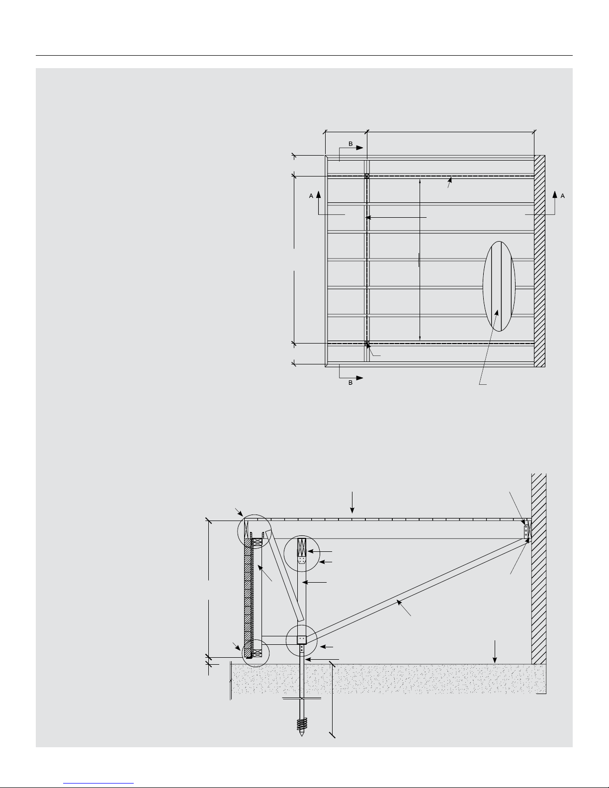
64 – TANDEM® SYSTEM
CONSTRUCTION OF OUTDOOR LIVING COMPONENTS WITH THE TANDEM MODULAR GRID
WOODEN DECK
Warning: We recommend installing a Tandem wall only for
new wooden decks to be built according to the minimum
specifications and data detailed below.
The wooden deck should be built with a structure composed of 2 × 8 joists
spaced ever y 16" (400 mm) or less. The deck beams must be made of
at least two 2 × 8 boards.
The beams are supported on 4 × 4 (89 × 89 mm) wooden posts.
The posts themselves are supported on screw piles designed for
this purpose (helical piles).
Maximum length of wood joists in both directions: 2400 mm (8 ft).
Minimum overhang of 300 mm (12" ) and maximum overhang of 600 mm (24").
To attach the components of the wooden structure to the deck joists,
you should use #10 stainless steel wood screws.
Simpson Strong-Tie hardware (or equivalent) should be used.
A waterproofing membrane must be installed on top of the wood frame
to protect the wood from water saturation and rot (in the case of wood
board flooring with free space). The membrane can be omitted for waterproof
deck flooring such as fiberglass.
It is recommended to leave a space of ⅛1/ 8" to 1/4" between the wooden
boards of the deck for ventilation under the deck so as not to trap moisture.
WOODEN DECK SKIRTING –
CROSS-SECTION A-A
A Simpson Strong-Tie LUS 26 and LUS 26-2 (GA 18)
galvanized steel joist hangers, or equivalent
B 2x8 continuous rail attached to foundation wall with
Hilti KB-TZU 12
×
140 mm (1/2 in x 5 1/2 in) anchors,
or equivalent
Alternative: joists resting on foundation wall.
C Diagonal brace at mid-height for wall
over 1200 mm (4 in) tall
D Floor coverings 2
×
6 spaced at 6 mm (1/4 in)
Note: During construction, 2
×
4 posts
should face floor joists to enable construction
of assemblies
FLOOR STRUCTURE –
PLAN VIEW
2 × 8
2-2 × 8
2 × 8 @ 16 in c/c
2-2 × 8
4 × 4 Post
Vertical bracing
2-2
× 8 beams
Joists 2
× 8 or Beams 2-2 × 8 (see note)
2-2
×
4
2-2 × 4
DETAIL 4
DETAIL 2
Screw pile Ø 60mm (2-3/8 in) min.
1.8 m (6 ft) or frost depth according to locality
Diagonal bracing on upright posts
Finished grade
C
DETAIL 3
DETAIL 1
D A
B
Min. 75 mm
(3 in) clearance
1524 mm
(5 ft)
4 × 4 Post
vertical bracing
(see cross-section B-B)
Diagonal bracing
2
× 6 Floor covering
Spaced ever y 6 mm (1/4")
2438 mm
(8 ft)
2438 mm
(8 ft)
300 mm
(1 ft)
300 mm
(1 ft)
600 mm
(2 ft)
2 × 4 @ 16 in c/c
2-2
×
4 each side of post
Page 65
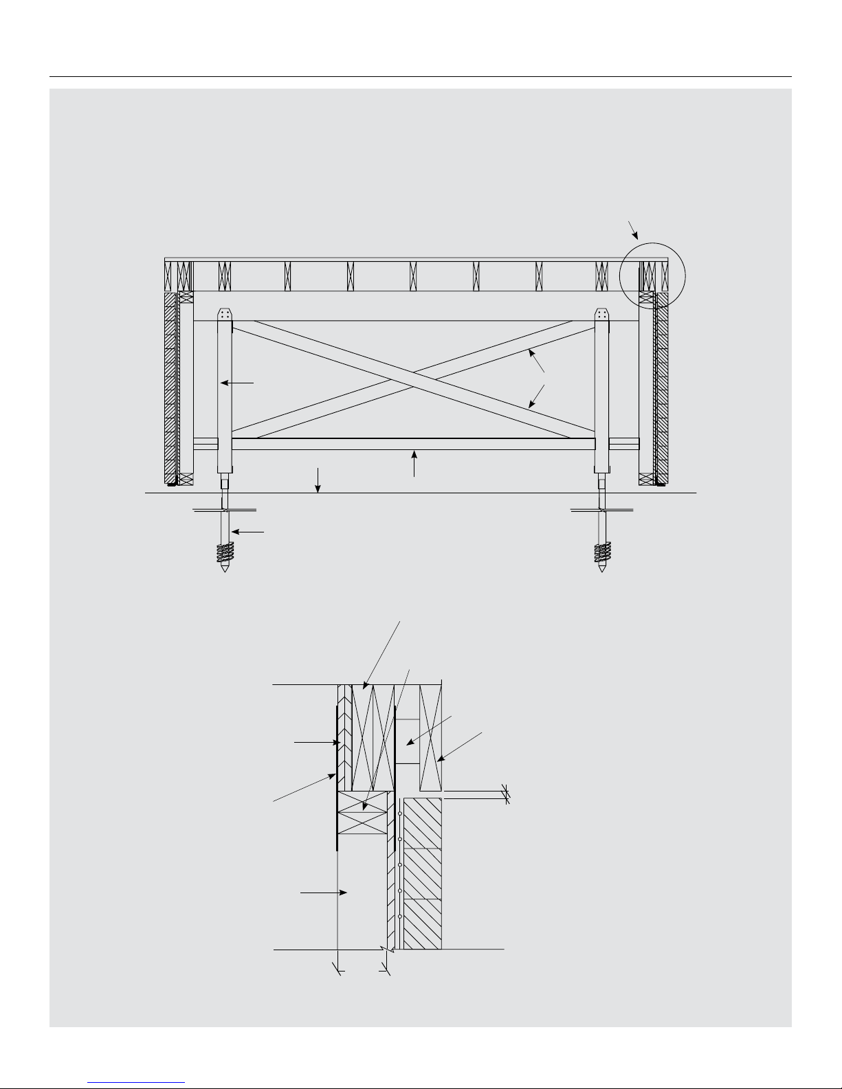
2 × 8
TANDEM® SYSTEM – 65
CONSTRUCTION OF OUTDOOR LIVING COMPONENTS WITH THE TANDEM MODULAR GRID
WOODEN DECK SKIRTING –
CROSS-SECTION B-B
DETAIL 5
Beam 2-2 × 8
4
× 4 Post
DETAIL 5
Screw piles
Minimum capacity of 17 kN (4000 lbs) weighted load
and 13 kN (3000 lbs) total weight
2-2
× 4
2-2 × 4
Double 2
× 4 rail interrupted
at upright of 2-2
× 8 beam
2-2
× 8
Wooden blocks
Plywood 2 × 1/2 in
2
× 4 at 16 in c/c
Simpson Strong-Tie
LSTA9 steel connector,
or equivalent
89 mm
(3 1/2 in)
12 mm clearance
(1/2 in)
2 × 4 @ 16 in c/c
2 × 4 @ 16 in c/c
Finished grade
Page 66
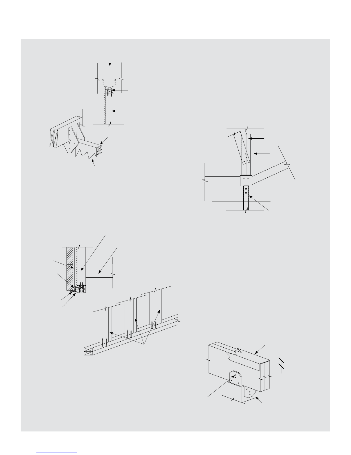
66 – TANDEM® SYSTEM
CONSTRUCTION OF OUTDOOR LIVING COMPONENTS WITH THE TANDEM MODULAR GRID
WOODEN DECK SKIRTING –
DETAILS
Soprema waterfproofing membrane
on top of beam
76 mm
(3 in)
Post 4 × 4
2
× 8 joist
or 2-2
× 8 beam
Simpson Strong-Tie
H1, H5 or H8 fasteners
or equivalent
(each side of wall)
Plywood
12 mm (1/2 po)
2 #10 Screw × 3 1/2 in long
in each 2 × 4
2-2
× 4s screwed diagonally
on 2-2
× 4s ver tically
Soprema waterfproofing membrane
on top of assembly
4
× 4 Post
(veneers not showing)
2 #10 screw × 3 1/2 in long
in vertical 2 × 4s
Post
2-2 × 4 vertical bracing
between columns
Fixing bolt with drilling on site,
2 bolts Ø 16 mm (3/ 8 in)
(according to manufacturer's
recommendations)
Techno- Metal Post #UF2-4G
galvanized fixed support system,
or equivalent
* Screwed diagonally on the 4 × 4 post
with #10 screws × 76 mm (3 1/2 in) long
(4 screws minimum per assembly)
Simpson Strong-Tie BSC 2-2/4 galvanized
fasteners, or equivalent, with #10 screws,
50 mm (2 1/2 in) long (assemble according
to manufacturer's recommendations)
2-2
×
8
DETAIL 4
DETAIL 3
3D VIEW
DETAIL 1
DETAIL 2
2-2 × 4*
2 × 4 @ 16 in c/c
(Doubled at upright posts)
Tandem Gr id
#10 stainless steel screws
× 75 mm (3 in) long
at 200 mm (8 in) c /c
Galvanized shelf angle
Plywood 12 mm (1/2 in)
2
× 4 at 400 mm
(16 in) c/c
2-2
×
4*
1-2
×
4*
each side
of post
Page 67

Page 68
logo FSC EN de l’imprimeur
1-888-PERMACON
PERMACON.CA
PERMACON BOLTON
3 BETOMAT COURT
BOLTON, ONTARIO L7E 2V9
TELEPHONE: 905-857-6773
FAX: 905-857-4774
PERMACON LONDON
1201 BRYDGES STREET
LONDON, ONTARIO N5W 2B5
TELEPHONE: 519-453-9501
FAX: 519-453-8849
PERMACON MILTON
8375 5th SIDE ROAD
MILTON, ONTARIO L9T 2X7
TELEPHONE: 905-875-4215
FAX: 905-875-1350
PERMACON OTTAWA SOUTH
6860 BANK STREET
METCALFE, ONTARIO K0A 2P0
TELEPHONE: 613-821-0898
1-800-361-2707
FAX: 613-821-4593
PERMACON OTTAWA WEST
6775 HAZELDEAN ROAD
STITTSVILLE, ONTARIO K2S 1B9
TELEPHONE: 613-821-0898
1-800-361-2707
FAX: 613-821-4593
PERMACON MONTREAL
8140, BOMBARDIER STREET
ANJOU, QUEBEC H1J 1A4
TELEPHONE: 514-351-2120
FAX: 514-351-7454
PERMACON QUEBEC
8845, PIERRE-BERTRAND BLVD
QUÉBEC, QUEBEC G2K 1W2
TELEPHONE: 418-622-3333
FAX: 418-622-9603
PERMACON SHERBROOKE
1080, PANNETON STREET
SHERBROOKE, QUEBEC J1K 2B4
TELEPHONE: 819-564-1414
FAX: 819-564-1340
PERMACON TROIS-RIVIÈRES
1100, DE LA COMMUNE BLVD
TROIS-RIVIÈRES, QUEBEC G9A 2W6
TELEPHONE: 819-378-2721
FAX: 819-378-6125
 Loading...