

Perlick HP15, HP24, HP48, Signature HP15TS, Signature HP24TS Operation & Installation Manual
...Page 1

Luxury
Operation &
Installation Manual
Signature Series (HP15-, HP24- and HP48-inch models)
Beer Dispenser Models Only
HP15TS
HP24TS
HP48RT
Form No. Z2259
Rev. 06/07/2012
Page 2

Page 3

Operation & Installation Manual
Signature Series Beer Dispensers (HP15, HP24 and HP48 models)
Table of Contents
Introduction ..........................................................................................................3
Warranty Registration ..................................................................................... 3
General Precautions .........................................................................................4
Installation Specications .............................................................................4
Overall Dimensions and Drawings ......................................................... 5
Preparing the Space ........................................................................................ 8
Preparing the Electrical Connections ...................................................8
Unpacking and Moving .................................................................................8
Anti-tip Brackets ................................................................................................. 9
Installation .............................................................................................................10
Shelving ...................................................................................................................11
Toe Plate Wood Overlay Drawings..........................................................12
Shelf and Drawer Removal .......................................................................... 14
INTRODUCTION
Congratulations on your purchase of a Perlick residential
refrigeration product. Perlick has taken its expertise and experience
into creating the highest quality and most innovative residential
products on the market. Perlick’s product oering gives you the
opportunity to enjoy the functionality and user friendliness in
just about any room of your home, including kitchens, bedrooms,
entertainment rooms, basements and even bathrooms. All Perlick
products are built with commercial-grade stainless steel – providing
you with the beauty and durability for a lifetime of use.
This Installation and Operation Manual will answer your questions
about the features, operation and maintenance of your Refrigerated
Cabinet model. If you have questions that are not addressed here,
call 800 558-5592.
IMPORTANT : PLEASE READ all instructions completely before
attempting to install or operate the unit. First, as you follow these
Installation and Operation instructions, take particular note of the
DANGER!, CAUTION! and WARNING! symbols when they appear.
This information is important for the safe and ecient installation,
operation and care of your Perlick unit.
Door Options and Wood Overlay Installation .................................. 15
Operation ............................................................................................................... 24
General .................................................................................................................24
Temperature Controller ..............................................................................25
Unit Temperatures/Product Temperature ......................................26
Cleaning and Maintenance .........................................................................26
Installing Tapping Equipment ...................................................................27
Mounting Hole Template for Draft Arms ............................................ 30
CO2 Connections .............................................................................................. 31
Tapping a Keg ......................................................................................................32
Cleaning the Beer System ............................................................................33
Pouring the Perfect Glass of Beer ............................................................ 34
Troubleshooting ................................................................................................. 35
Warranty ..................................................................................................................37
Once the unit is completely installed, we suggest you keep this
manual and purchasing documentation in a safe place for future
reference. Should problems occur: refer to the troubleshooting
section of this manual. The information will help you quickly identify
a problem and get it remedied. In the event you require assistance,
please contact the dealer where you purchased your unit.
WARRANTY REGISTRATION CARD
To request information or service, the model number and serial
number must be provided. This information is located on the inside
ceiling of the unit and on the warranty registration card included
with information packet shipped with the unit.
IMPORTANT : Read through the included warranty statement
then complete and mail the Warranty Registration Card as
soon as possible to validate the registration date. Warranty
registration can also be done online at www.perlick.com. If
warranty registration is not completed, Perlick will use the date
of sale as the rst date of warranty for the unit. Please record the
purchase date of the unit and the dealer’s name, address and
telephone number below.
DANGER
Indicates a hazard that will result in serious injury or death if
precautions are not followed.
WARNING
Indicates a hazard may cause serious injury or death if
precautions are not followed.
CAUTION
Indicates a hazard where minor injury or product damage may
occur if you do not follow instructions.
MODEL NUMBER: ____________________________________
SERIAL NUMBER: ____________________________________
PURCHASE DATE: ___________________________________
DEALER NAME & ADDRESS:
__________________________________________________
__________________________________________________
__________________________________________________
DEALER PHONE: ____________________________________
3
Page 4
Operation & Installation Manual
Signature Series Beer Dispensers (HP15, HP24 and HP48 models)
GENERAL PRECAUTIONS
DANGER
Risk of child entrapment, before you throw away your old
refrigerator or freezer, take o the doors and leave shelves in
place so that children may not easily climb inside.
DANGER
Altering, cutting of the power cord, or removal of the power
cord, removal of power plug, or direct wiring can cause serious
injury, re and/or loss of property and/or life and will void the
warranty.
WARNING
• Never attempt to repair or perform maintenance on the unit
until the electricity has been disconnected.
• The anti-tip kit must be installed on this unit before it is used.
Never use the drawers, shelves or door as steps or to support
more than they were designed to support.
INSTALLATION INSTRUCTIONS
CAUTION
• Do not lift unit by drawer or door handles.
• Failure to clean the condenser every three (3) months can
cause the unit to malfunction. This could void the warranty.
• Never install the unit behind closed doors. Be sure front
louvered toe plate is free of obstruction. Obstructing the
airow can cause unit to malfunction, and may void the
warranty.
CAUTION
Use only genuine Perlick replacement parts. Imitation parts can
damage the unit, and may void the warranty.
GENERAL
• All electrical instructions assume that outlet is located 4 to 10
inches from oor.
• Floor must be level in area of installation. Leg levelers are used
for ne-tune adjustment only and should not be used to compensate for oor dierences exceeding 1/2-inch.
• When moving unit into position, take care to protect oor surface with cardboard, rugs, etc.
• Never attempt to move unit without the aid of at least one
other person.
• Always secure door shut prior to moving the unit.
FINISHED OPENING REQUIREMENTS
15” Signature Series
Height Depth Width
34-3/8” minimum,
35-1/2” maximum
24” Signature Series
Height Depth Width
34-3/8” minimum,
35-1/2” maximum
48” Signature Series
Height Depth Width
34-3/8” minimum,
35-1/2” maximum
24” 15”
24” 24”
24” 48”
4
Page 5
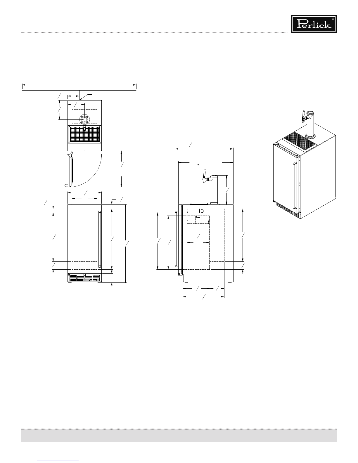
HP15TS Model
SCALE: 1:10
DATE:
95004
9/30/09
Signature Series HP15 Models
(Figure 1)
electrical outlet must be located
1
5
"
16
7
8
"
16
5
1
"
8
50" Area in which
7
"7
16
7
14
8
11"
Power cord 65/8" off floor.*
Min. clearance
for door swing.
"
*
Leg leveler can add
3/4" to these dimensions
when fully extended.
15
"
15
16
15
1
"
16
Operation & Installation Manual
Signature Series Beer Dispensers (HP15, HP24 and HP48 models)
Tapping
7
25
" Values may change
16
due to custom pull
with a wood overlay door.
24"
(with
1/16" toleramce)
3
12
"
4
3
21
"
8
1
3
"
2
PERLICK CORPORATION
MILWAUKEE, WI 53223
9
26
16
*3 7/8"
3
9
"
"
1
"*34
4
7
1
" 24
8
"
23
2
Typical
sixth
barrel.
11
7
4
" 6
8
3
18
"
16
1
"
4
1
23
"
16
1
3
"
2
DAS
DR.:
PRINTED
5
Page 6
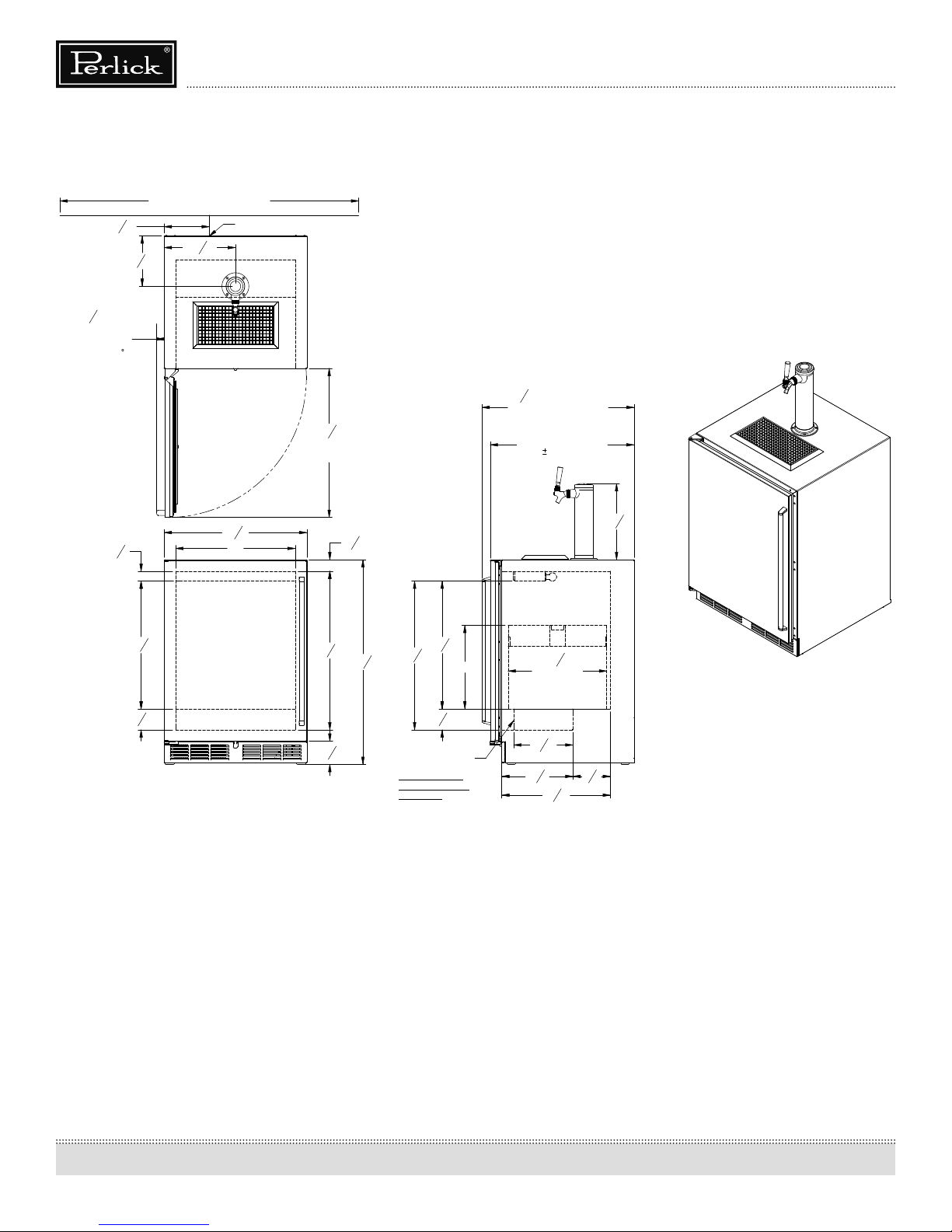
HP24TS Model
95005
9/30/09
SHEET 2 OF 3
(Figure 2)
electrical outlet must be located
9
7
"
16
7
"8
16
Operation & Installation Manual
Signature Series Beer Dispensers (HP15, HP24 and HP48 models)
50" Area in which
Power cord 65/8" off floor. *
15
"
11
16
Signature Series HP24 Models
Tapping
1
1
" Min.
4
clearance from
a corner to
acheive 90
door swing.
5
1
"
8
3
21
"
8
1
3
"
2
PERLICK CORPORATION
MILWAUKEE, WI 53223
PROPERTY OF THE PERLICK CORP.
NOT TO BE COPIED OR USED DETRIMENTAL TO OUR INTERESTS
23
20"
Leg levelers can add
*
3/4" to these dimensions
when fully extended.
7
25
" Value may change
16
due to custom pull
15
24
"
16
Min. clearance
for door swing.
7
"
8
15
1
"
16
3
21
9
26
"
16
1
34
*
"
4
7
*3
"
8
Shelf included with
dispensing cabinets.
Also fits two sixth
barrels when shelf
is removed.
"
8
7
24
"
8
14"
1
3
"
2
with a wood overlay door.
24"
1/16" tolerance)
(with
1
16
"
2
Typical
quarter barrel.
15
9
"
16
7
11
8
18
" 6
3
"
16
1
4
3
12
"
4
SCALE: 1:10
DAS
DR.:
"
PRINTED
4/12/2012
DATE:
6
Page 7
Operation & Installation Manual
50" Area in which
20 11/16"
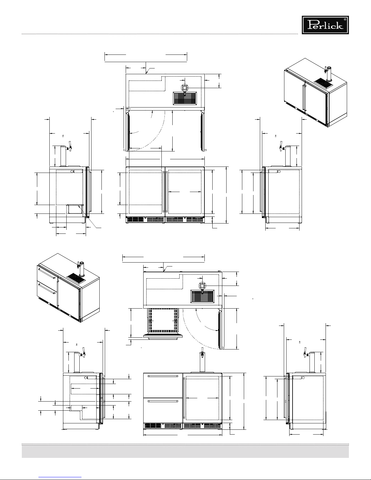
Signature Series HP48 Models
*4"
Signature Series HP48 Models
Signature Series Beer Dispensers (HP15, HP24 and HP48 models)
HP48RT Models
Door (Figure 3)/Drawer
Models (Figure 4)
25 7/16" Values may change
due to custom pull
with a wood overlay door.
24"
(with 1/16" tolerance)
12 3/4"
19 5/8"
5 1/4"
1 1/4" Min.
clearance from
a corner to
acheive 90
door swing.
26 9/16"
50" Area in which
electrical outlet must be located.
12 1/4"
pullout shelf
19 5/8"
5 1/4"
90° Swing
required for
clearance.
19 7/8"
Power cord 81/4" off floor.*
24 15/16"
Min. clearance
for door swing.
47 7/8"
19 7/8"
11 15/16"
8 7/16"
* Leg leveler can add
3/4" to these dimensions
when fully extended.
26 9/16"
*34 5/16"
26 9/16"
24 7/8"
25 7/16" Values may change
due to custom pull
with a wood overlay door.
24"
(with 1/16" tolerance)
12 3/4"
6 3/8" 11 3/4"
18 1/8"
25 7/16" Values may change
due to custom pull
with a wood overlay door.
(with 1/16" tolerance)
12 3/4"
3 3/16"
6 3/4" 10 1/2"
24"
17 1/4"
Shelf included with
dispensing cabinets.
1 3/8"
9 3/16"" Max.
6 3/16"
10 13/16" Max.
8 3/8"
17 11/16"
product ht.
product ht.
electrical outlet must be located.
12 1/4"
Power cord 81/4" off floor.*
17 13/16"
Inside Drawer
(Top & Bottom)
*4"
11 15/16"
90°
8 7/16"
1 1/4" Min.
clearance from
a corner to
acheive 90
door swing.
24 15/16"
Min. clearance
for door swing.
* Leg leveler can add
3/4" to these dimensions
when fully extended.
26 9/16" 19 7/8"
*34 5/16"
26 9/16"
20 11/16"
25 7/16" Values may change
24 7/8"
due to custom pull
with a wood overlay door.
(with 1/16" tolerance)
SCALE: 1:12
24"
12 3/4"
7
Page 8

Operation & Installation Manual
Signature Series Beer Dispensers (HP15, HP24 and HP48 models)
PREPARING THE SPACE
Make sure that the space that the opening where the Perlick
cabinet(s) is/are to be installed is properly prepared. Refer to Figure
1 (page 5), Figure 2 (page 6) and Figure 3 (page 7) to ensure proper
space dimensions and electrical service are correct for the model
to be installed.
CAUTION
If cabinet is being installed under a countertop it is recommended
that the countertop be supported by structure other than the
refrigerated cabinet to prevent damage to the counter top.
IMPORTANT NOTE: For a cabinet door to operate properly, the
door must open a minimum of 90°. Use a minimum 3-inch ller in
corner installations to assure a 90° door opening. For HP15 models,
allow 16” clearance in front of the unit. For HP24 and HP48 units,
allow 24” clearance in front of the unit for full door swing, shelf pullout or drawer pull-out.
IMPORTANT NOTE: Make sure the oor under the unit is level
with the surrounding nished oor. Protect a nished oor with
plywood, cardboard or some other suitable material before moving
the unit into place. Failure to do this may result in damage to the
oor.
PREPARING ELECTRICAL CONNECTIONS
A 115 volt, 60Hz, 15 amp circuit breaker and electrical supply are
required. A separate circuit is required for each Perlick unit installed.
Follow the National Electrical Code and local codes and ordinances
when installing the receptacle.
All Perlick units come equipped with a NEMA 5-15P 90° plug with
a minimum of 5-feet of cord extending beyond the rear of the
cabinet. The electrical outlet must be ush with or recessed into
the back wall.
Where a two-prong wall receptacle is encountered or a longer
power cord is required, contact a qualied electrician to have it
replaced in accordance with applicable electrical cords.
DANGER
Failure to comply with the above electrical guidelines may result
in possible injury, death, re or loss of property.
UNPACKING AND MOVING
CAUTION
Do not cut cardboard sleeve covering the unit. Cutting may
result in damage to the exterior of the cabinet.
1. Uncrate the unit outside on a at surface. Remove the cardboard sleeve by removing the banding holding the sleeve
to the shipping base. Carefully lift the cardboard sleeve up
over the top of the unit.
2. Carefully lift unit o base and onto a hand truck or dolly (this
should be done with a minimum of two people; larger units
may require additional helpers!). Make sure the unit is balanced on transporting device using soft, exible strapping.
Protect unit surfaces with cloth material where strapping
contacts unit.
3. Before moving unit, secure door to unit with tape to the
door closed.
4. Carefully move unit to installation site and place in front of
opening.
WARNING
A minimum of two people should lift the cabinet o the base to
prevent possible personal injury.
IMPORTANT NOTE: Never use an extension cord to extend the
power cord to the electrical receptacle.
DANGER
ELECTROCUTION HAZARD
Electrical grounding is required. This appliance is equipped with
a three prong (grounding) polarized plug for your protection
against possible shock hazards.
• Never remove the round grounding prong from the plug.
• Never use a two-prong grounding adapter.
• Never use extension cords to connect power to the unit.
8
Page 9
Signature Series Beer Dispensers (HP15, HP24 and HP48 models)
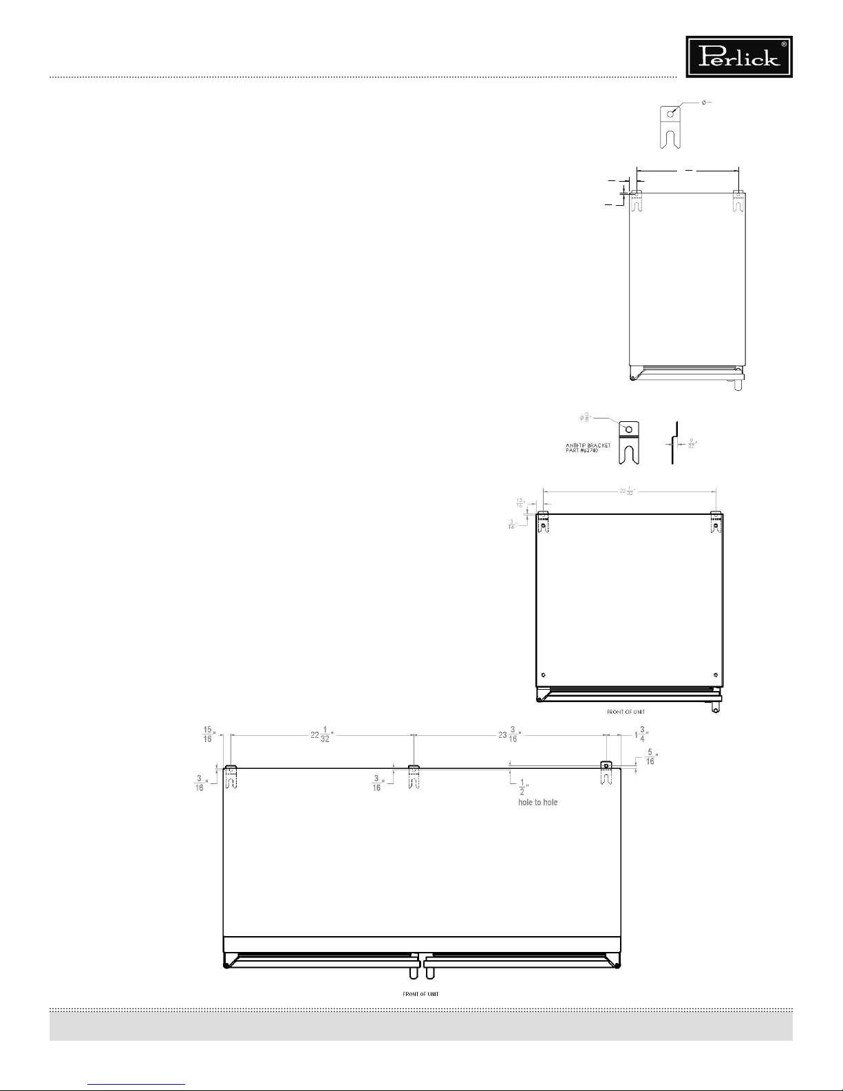
FRONT OF UNIT
ANTI-TIP BRACKETS
WARNING
Unit may tip forward if loaded racks/shelves are all pulled
out at the same time. To prevent tipping and provide a stable
installation, the unit must be secured in place with the anti-tip
brackets provided with the unit.
A set of metal anti-tip brackets and necessary hardware is supplied
with the unit. The anti-tip brackets, when properly installed, should
secure the rear legs and prevent the unit from tipping forward.
Some installation sites may require modication to provide a secure
surface for attaching brackets. Refer to Figures 5 and 6 (right) and
Figure 7 (below) for mounting bracket locations for 15”, 24” and 48”
Signature Series models.
Operation & Installation Manual
Figure 5 - 24” Anti-Tip Kit Drawing
15
"
16
3
"
16
ANTI-TIP BRACKET
PART #63740
1
13
"
32
3
"
8
IMPORTANT NOTE: If installing on a concrete oor, concrete
fasteners are required and are not included in the Anti-Tip Kit.
Figure 7 - 48” Anti-Tip Kit Drawing
Figure 6 - 24” Anti-Tip Kit Drawing
9
Page 10
Operation & Installation Manual
Signature Series Beer Dispensers (HP15, HP24 and HP48 models)
INSTALLATION
CAUTION
Finished ooring should be protected with the appropriate
material to avoid damage from moving the unit.
If unit has been laid on its back or sides, place unit upright and
allow minimum of 24 hours before connecting power.
1. Plug in the unit into the 15 amp grounded outlet located
in the installation opening. With power applied to the unit,
check that the lighting and cooling function operate properly, then turn o power to the wall outlet at the circuit breaker.
WARNING
Shut o power to the wall outlet before installing unit into the
opening.
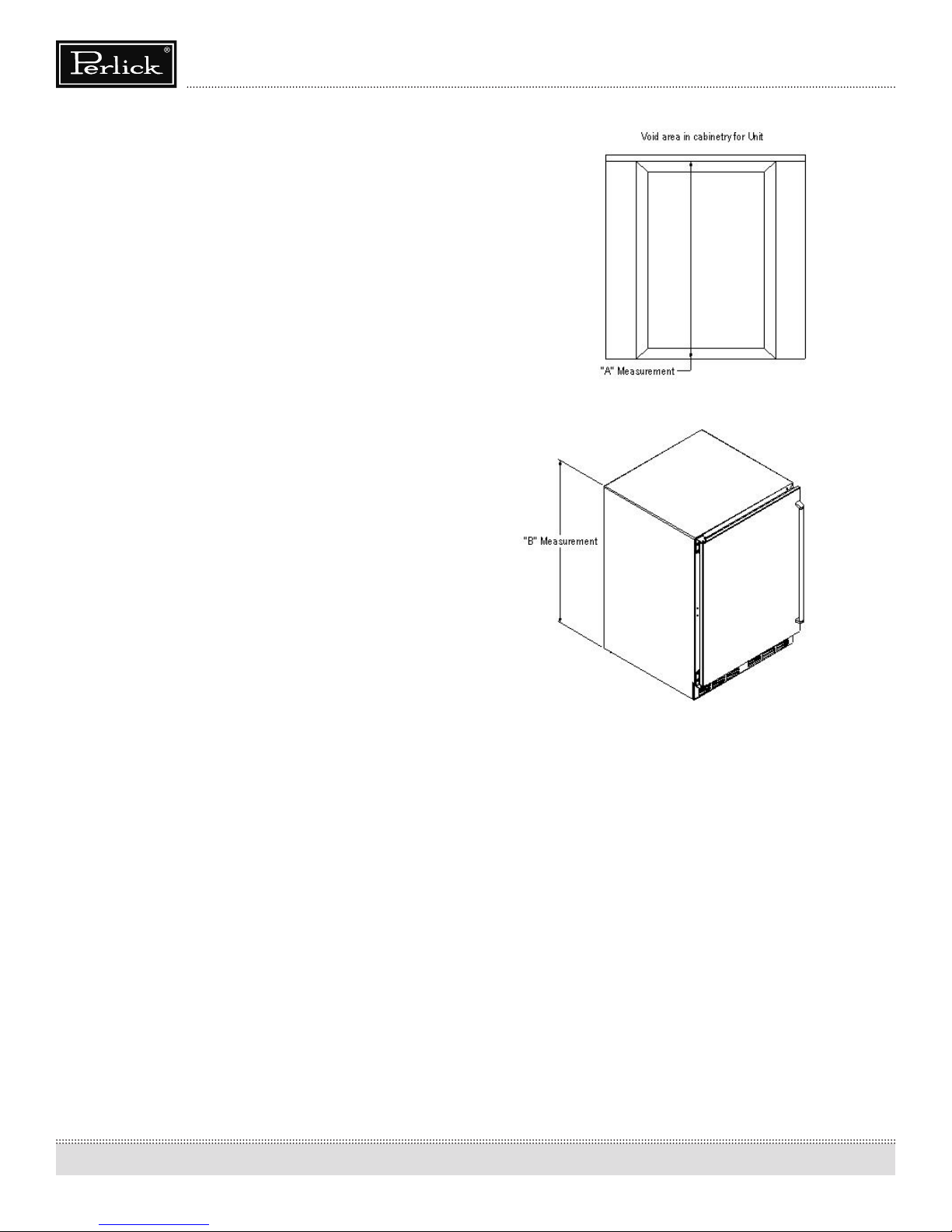
2. Check that the following are level and square:
• front face and interior opening
• installation opening and oor surface
• countertop bottom front edge
IMPORTANT NOTE: The oor under the unit must be at the same
level as the surrounding nished oor.
Figure 8 - Leveling
3. If all surfaces are level, refer to Figure 8 (right) and perform
the following:
a. Measure from the oor to the bottom of the front edge of
the countertop.
b. Mesure the rear of the unit cabinet from oor to top of
cabinet, at back corners.
c. Adjust rear legs so B measurement equals A measurement.
Usingt an adjustable wrench of pliers, turn legs counterclockwise to raise the unit or clockwise to lower the unit.
IMPORTANT NOTE: Leveling legs should not extend more than
3/4” from bottom of the unit.
4. Slide cabinet into position. Make sure the rear levelling legs
slide under the anti-tip brackets. Push the unit into the opening until the bottom front edge of the unit is ush with the
surrounding cabinetry, or until the rear legs are tight against
the anti-tip brackets.
5. Shim the front of the unit so the front face is ush with the
surrounding cabinetry. Adjust the front legs to support the
countertop at the shimmed height. Using an adjustable
wrench or pliers, turn the legs counterclockwise to raise the
unit or clockwise to lower the unit. Countertop should be
resting on top of the unit.
IMPORTANT NOTE: If countertop is not resting entirely on unit top,
shim the countertop to prevent damage to the countertop.
CAUTION
To prevent damage to the countertop and unit underneath, do
not place heavy objects on countertop directly above the unit.
6. Check interior door openings inside the cabinet to ensure
the cabinet is level. Reinstall all shelving and sliding drawers
squarely into slide brackets and proper slide bracket grooves.
When sliding shelving and drawers are installed properly
a click should be heard from both slide bracket retaining
clips and should slide smoothly in the tracks. When sliding
shelving or drawers are pulled out to full extension a stop is
activated to prevent additional pull-out.
CAUTION
Improper shelving or drawer installation may not actuate slide
top mechanism.
10
Page 11
Operation & Installation Manual
Signature Series Beer Dispensers (HP15, HP24 and HP48 models)
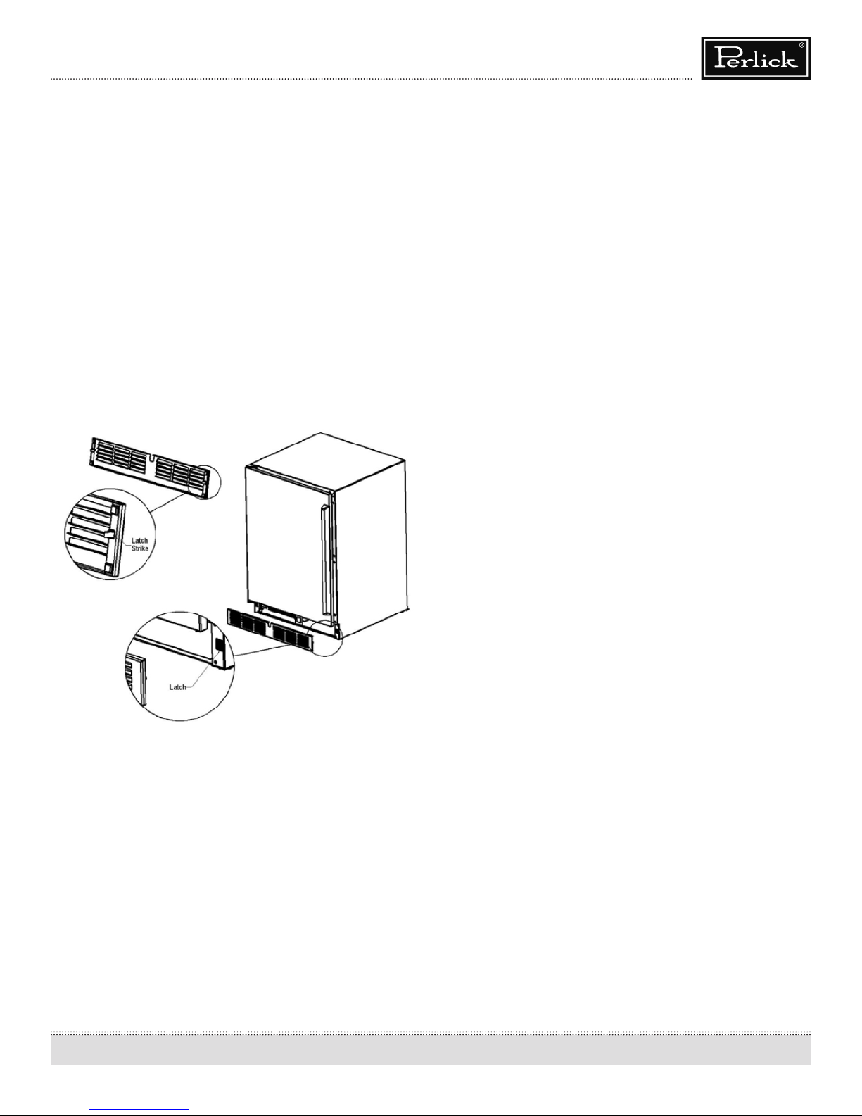
TOE PLATE INSTALLATION
When the unit is secured in place, install the louvered toe plate.
Secure louvered toe plate by snapping the latch into the latch
catch on the unit. Refer to Figure 9 (below) for Toe Plate Installation
Illustration and Figures 10 (page 12) and 11 (page 13) for Toe Plate
Wood Overlay template.
CAUTION
The louvered toe plate must be removed to service the unit. The
oor cannot interfere with removal. The louvered sections must
not be covered or obstructed to prevent proper air circulation.
IMPORTANT NOTE: To achieve maximum performance, interior
louver openings and fan guard openings should never be
obstructed.
Figure 9- Toe Plate Installation
SHELVING
HP15TS Single Door Beer Dispenser
Shelving not available
HP24TS Single Door Beer Dispenser
Shelving not available
HP48RT Two Door Refrigerator/Beer Dispenser
The two door refrigerator/beer dispenser (HP48RT) comes standard
with two full-extension black vinyl-coated pullout shelves on the
refrigerator side. Shelving not available on beer dispenser side.
HP48RT Drawer/Door Refrigerator/Beer Dispenser
Shelving not available
11
Page 12
Operation & Installation Manual
2
3
B
A
1
C
THIS DOCUMENT / PUBLICATION / SOFTWARE / DRAWING CONTAINS PROPRIETARY INFORMATION WHICH IS THE PROPERTY OF THE PERLICK CORPORATION. IT MAY NOT BE REPRODUCED OR TRANSMITTED IN ANY FORM, ELECTRONIC OR MECHANICAL,
INCLUDING PHOTOCOPYING, RECORDING, OR USED IN ANYINFORMATION STORAGE, TRANSMISSION, OR RETRIEVAL SYSTEM, WITHOUT WRITTEN PERMISSION FROM THE PERLICK CORPORATION. COPYRIGHT 2001 PERLICK CORPORATION. ALL RIGHTS RESERVED.
SHEET 3 OF 4
SCALE =
Perlick Corporation
Milwaukee, Wisconsin
DWG NO.
REVISIONS
GRILL, WOOD
15IN
WOOD GRILL
WOOD GRILL, 15IN
1:3
4/23/2008
J:\Dwg\_ Assembly\HHC GEN2\HHC GEN2 24IN RESIDENTIAL\Wood Grill.slddrw
Signature Series Beer Dispensers (HP15, HP24 and HP48 models)
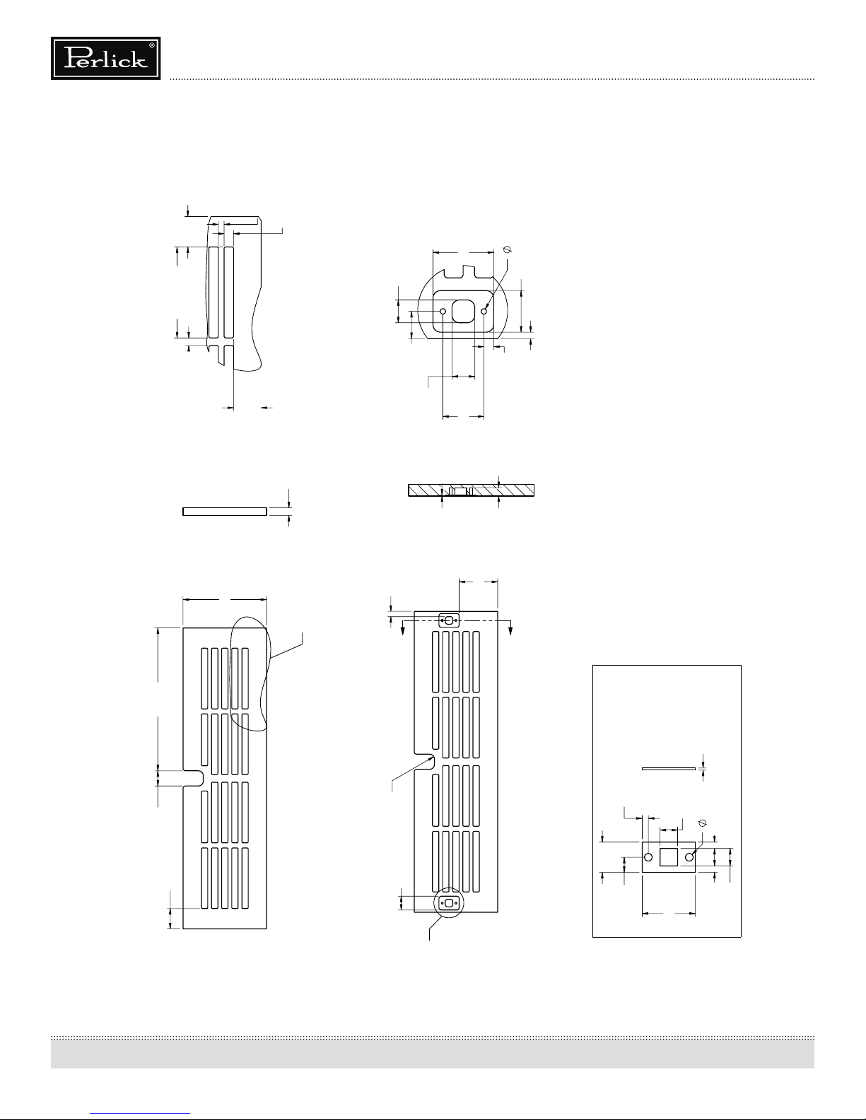
Figure 10- Toe Plate Wood Overlay Template for HP15TS
1"
TYPICAL
3"
1/4"
TYPICAL
4 1/8"
TYPICAL
3/16"
29/32"
TYPICAL
5/16"
DETAIL C
SCALE 1 : 2
3/8"
C
3/8"
17/64"
B
29/64"
3/8"
1/32"
1"
43/64"
3/32"
11/16"
DETAIL D
SCALE 1 : 1
7/64"
5/32"
SCALE 1 : 2
SECTION B-B
9/32"
1 29/32"
B
NOTE: ALL INTERNAL RADII ARE 1/8IN UNLESS OTHERWISE SPECIFIED
REFERENCE:
TITLE:
DATE
4/23/2008
4/23/2008
4/23/2008
NAH
NAH
SIGNATURES
DRAWN
DESIGNED
CHECKED
BREAK SHARP EDGES - 015 X 45°.
RADIUS SHARP FILLETS - .015 TO .031
DIMENSIONS ARE IN INCHES
TOLERANCES:
.X= ,
.XX = ,
.XXX = ,
ANGULAR: ±1.0°, FRACTIONS: ±1/16
UNLESS OTHERWISE SPECIFIED:
METAL CLIP REQUIRED FOR SNAP IN RETAINER THAT
ASSEMBLES GRILL TO THE UNIT. THIS CLIP MUST BE
SCREWED TO THE GRILL USING THE FEATURES SHOWN
IN DETAIL VIEW "D"
PART NO.
QTY.:
FINISH:
MATERIAL:
WOOD
PURCHASE REC.:
7 1/16"
FRONT VIEW
3/4"
1"
12
1/4"
R
11/16"
THICK (20GA)
RECOMMENDED
GALVANIZED OR
STAINLESS STEEL
1/32"
REAR VIEW
3/32"
9/32"
1/8"
1/2"
1/4"
7/64" 7/64"
9/32"
7/8"
D
Page 13

Operation & Installation Manual
2
3
B
A
1
C
THIS DOCUMENT / PUBLICATION / SOFTWARE / DRAWING CONTAINS PROPRIETARY INFORMATION WHICH IS THE PROPERTY OF THE PERLICK CORPORATION. IT MAY NOT BE REPRODUCED OR TRANSMITTED IN ANY FORM, ELECTRONIC OR MECHANICAL,
INCLUDING PHOTOCOPYING, RECORDING, OR USED IN ANYINFORMATION STORAGE, TRANSMISSION, OR RETRIEVAL SYSTEM, WITHOUT WRITTEN PERMISSION FROM THE PERLICK CORPORATION. COPYRIGHT 2001 PERLICK CORPORATION. ALL RIGHTS RESERVED.
SHEET 1 OF 4
Perlick Corporation
Milwaukee, Wisconsin
REVISIONS
GRILL, WOOD
STAND ALONE
WOOD GRILL
1:3
4/23/2008
J:\Dwg\_ Assembly\HHC GEN2\HHC GEN2 24IN RESIDENTIAL\Wood Grill.slddrw
Signature Series Beer Dispensers (HP15, HP24 and HP48 models)
Figure 11- Toe Plate Wood Overlay Template for HP24TS and HP48RT
7/32"
3/8"
29/64"
1"
TYPICAL
3"
3/8"
TYPICAL
DETAIL C
SCALE 1 : 2
TYPICAL
3/16"
TYPICAL
5/16"
3/8"
17/64"
3 27/64"
C
B
1/32"
1"
3/8"
43/64"
3/32"
11/16"
DETAIL D
SCALE 1 : 1
5/32"
SCALE 1 : 2
SECTION B-B
9/32"
B
SCALE =
TITLE:
4/23/2008
NAH
DRAWN
CHECKED
REFERENCE:
4/23/2008
QTY.:
DWG NO.
PART NO.
FINISH:
WOOD GRILL, STACKING
PURCHASE REC.:
DATE
SIGNATURES
DESIGNED
4/23/2008
NAH
NOTE: ALL INTERNAL RADII ARE 1/8IN UNLESS OTHERWISE SPECIFIED
BREAK SHARP EDGES - 015 X 45°.
RADIUS SHARP FILLETS - .015 TO .031
DIMENSIONS ARE IN INCHES
TOLERANCES:
.X= ,
.XX = ,
.XXX = ,
ANGULAR: ±1.0°, FRACTIONS: ±1/16
MATERIAL:
UNLESS OTHERWISE SPECIFIED:
WOOD
11 9/16"
1"
3/4"
1"
1/4"
R
23 7/8"
FRONT VIEW
11/16"
METAL CLIP REQUIRED FOR SNAP IN RETAINER THAT
ASSEMBLES GRILL TO THE UNIT. THIS CLIP MUST BE
SCREWED TO THE GRILL USING THE FEATURES SHOWN
IN DETAIL VIEW "D"
THICK (20GA)
RECOMMENDED
GALVANIZED OR
STAINLESS STEEL
1/32"
REAR VIEW
3/32"
9/32"
1/8"
1/2"
NOTE: GRILL SHOWN ON THIS PAGE IS FOR EITHER A SINGLE STAND ALONE UNIT OR
THE BOTTOM UNIT OF A STACKED CONFIGURATION
D
1 13/64" 1 13/64"
1/4"
7/8"
7/64" 7/64"
9/32"
13
Page 14

Operation & Installation Manual
Signature Series Beer Dispensers (HP15, HP24 and HP48 models)
Adjusting Full-extension Shelving (HP48RT only)
1. Pull the shelf out to its farthest position. Locate the tabs in the
middle of both extenders (Figure 12). Lift one tab up while
pushing the opposite tab down and pull shelf out.
2. Reposition each bracket separately. Grasp the middle of
the bracket, pull the front end up and out, then forward to
remove (Figure 13).
3. Place bracket at the desired position. Push the rear hook into
the rear key slot. Set front of the bracket on the wall hook.
4. Repeat for other bracket(s).
5. Push extenders completely into the unit. Align the shelf
grooves with the extenders and slide completely into the
unit.
Drawers
Drawer units (available on HP48RT model only) come standard
with two drawers. Like shelving, drawers are full-extension.
Figure 12- Tab location
Lift one tab up while pushing the
opposite tab down and pull shelf out
Figure 13 - Bracket and extender location
To remove drawers:
1. Pull the drawer out to its farthest point.
2. Locate the tabs in the middle on both sides of the extenders.
Press left tab up and right tab down; pull shelf out.
3. Move each extender separately. Hold the middle of one extender, pull the front up then move extender 1/2-inch to the
inside of unit. Pull up, then out.
4. Place extender at desired height, place rear stando screw
into rear pilaster, slide back. Place front stand-o screw into
front pilaster, slide down.
5. To return drawer, rst push both extenders completely in
then line up the shelf grooves and slide easily into the unit.
CAUTION
Completely empty the drawer before removing.
To remove brackets,
remove shelf, lift front
of bracket to disengage
the front key slot, and
pull forward to disengage
the rear key slot.
14
Page 15

DOOR OPTIONS
Operation & Installation Manual
Signature Series Beer Dispensers (HP15, HP24 and HP48 models)
Perlick residential units oer a variety of door panel design
alternatives; solid stainless steel, solid wood overlay, glass with
stainless steel trim and glass with wood overlay trim.
Solid stainless steel and stainless steel glass doors are shipped from
the factory with decorative stainless steel panels and handles in
place on the appliance.
Solid wood overlay and glass wood overlay doors are designed to
accept a decorative front panel to match surrounding cabinetry
and door handles. The panel and door handles are supplied by the
customer.
All Perlick units accept any of the above door congurations and
are fully interchangable.
IMPORTANT NOTE: Units with a beer dispenser only can utilize a
solid stainless steel door or solid wood overlay door.
IMPORTANT NOTE: Glass with stainless trim and glass with wood
trim may sweat in conditions with relative humidity over 75%.
WOOD OVERLAY INSTALLATION
Before beginning installation, check all components for proper t
and nish.
Panel drawings:
Refer to Figure 15 for 15” solid wood overlay panel (page 16).
Refer to Figure 17 for 24” solid wood overlay panel (page 18).
Refer to Figure 18 for 24” for glass wood overlay panel (page 19).
Refer to Figure 19 for 24” drawer wood overlay panel (page 20).
Door Lock Installation (optional)
When installing to wood overlay, perform lock installation before
mounting wood overlay to door.
1. See Figure 14 (below), attaching mounting bracket to wood
overlay.
2. Insert lock body and attach with nut.
Lock installation drawings:
Refer to Figure 16 for Lock Installation on 15” solid wood overlay
panel (page 17).
Refer to Figure 20 for Lock Installation on 24” solid wood overlay
panel (page 21).
Refer to Figure 21 for Lock Installation on 24” glass wood overlay
panel (page 22).
Refer to Figure 22 for Lock Installation on 24” drawer wood overlay
panel (page 23).
Figure 14 - Lock installation
Mounting bracket
Nut
WARNING
• All overlay doors require a trim panel of at least 3/4” thick.
• The solid wood overlay panel should not weight more than
20 pounds.
• The glass wood overlay panel should not weight more than
10 pounds.
The following instructions cover installing a solid wood overlay or
glass wood overlay panel and handle to a door or drawer.
IMPORTANT NOTE: Contact the factory or visit www.
bringperlickhome.com for full size wood overlay panel layouts.
Once on the site, select ‘Service and Support’ from the top menu
bar and click on ‘Wood Overlay Templates’. Take care in chosing the
correct template for your specic model.
IMPORTANT NOTE: You must install optional lock and handle
PRIOR to mounting the wood overlay onto the door frame.
Lock strike
Lockwasher
Lock body
Screw
Lock bracket
15
Page 16

Operation & Installation Manual
Signature Series Beer Dispensers (HP15, HP24 and HP48 models)
Figure 15 - Solid wood overlay panel template for HP15TS
16
Page 17

Signature Series Beer Dispensers (HP15, HP24 and HP48 models)
Figure 16 - Lock installation, solid wood overlay door panel for HP15TS
Operation & Installation Manual
17
Page 18

Operation & Installation Manual
Signature Series Beer Dispensers (HP15, HP24 and HP48 models)
Figure 17 - Solid wood overlay panel template for HP24TS and HP48RT
18
Page 19

Signature Series Beer Dispensers (HP15, HP24 and HP48 models)
Figure 18 - Glass wood overlay panel template for HP24TS and HP48RT
Operation & Installation Manual
19
Page 20

Operation & Installation Manual
Signature Series Beer Dispensers (HP15, HP24 and HP48 models)
Figure 19 - Wood overlay drawer panel template for HP24TS and HP48RT
20
Page 21

Signature Series Beer Dispensers (HP15, HP24 and HP48 models)
Figure 20- Lock installation, solid wood overlay door panel for HP24TS and HP48RT
Operation & Installation Manual
21
Page 22

Operation & Installation Manual
Signature Series Beer Dispensers (HP15, HP24 and HP48 models)
Figure 21 - Lock installation, wood overlay glass door panel for HP24TS and HP48RT
22
Page 23

Signature Series Beer Dispensers (HP15, HP24 and HP48 models)
Figure 22 - Lock installation, wood overlay drawer panel for HP24TS and HP48RT
Operation & Installation Manual
23
Page 24

Operation & Installation Manual
Signature Series Beer Dispensers (HP15, HP24 and HP48 models)
Handle Installation
CAUTION
Handle mounting on wood overlay door should be mounted on
overlay panel only (not the door) to avoid damage to the factory
door.
1. Handle must be attached to overlay before mounting overlay
onto door. Mark rear of wood overlay planel with handle
fastening locations.
2. Drill through wood overlay panel at marked locations taking
care not to damage the wood overlay panel.
3. Countersink screw heads so screw heads are ush with back-
side of panel. Attach handle to overlay panel.
CAUTION
Proper wood working materials and equipment should be used
to avoid damage or errors in workmanship.
Wood Overlay Panel Installation
Scan the QR code to the right with
your smart phone to watch a How-To
video on how to install Wood Overlay
panels onto Perlick doors, otherwise,
follow the instructions below.
OPERATION
General
The unit is equipped with a state-of-the-art refrigeration system.
The variable speed compressor automatically changes speed
based on system conditions and load. The cabinet is equipped with
an adjustable digital temperature controller and LED display.
Freezer units are frost-free models, meaning the evaporator coil
automatically defrosts on demand at predetermined intervals.
The controller also has a manual defrost soft button on the
front panel signied by a melting snowake. If depressed it will
automatically put the system into a defrost cycle.
Interior Light
The unit is equipped with an interior light that illuminates when
the door is open. The cabinet also comes standard with a manual
light switch located next to the light for displaying your products
through a glass door.
Always ensure that the manual switch is in the o position before
closing a solid wood or stainless door. If manual light switch is
left on for an extended period of time it may increase the cabinet
temperature, especially at the top and cause the refrigeration
system to run longer.
1. With the unit secured in position, open the door and make
sure panel’s pre-drilled holes align with door frame holes.
2. Loosely attach four corners of the overlay panel to the door
using #10 x 1” wood screws, installed through the door frame
from the rear.
3. Check for overall wood overlay panel t, position and func-
tion. Make minor adjustments as necessary. When panel is
properly aligned, tighten mounting screws securely. Install
the rest of the mounting screws and tighten securely.
CAUTION
Do not over-tighten wood overlay attachment screws as this
may damage the factory supplied door frame.
Loading Product
IMPORTANT NOTE: Before storing perishables, allow unit to run
for a minimum of 24 hours to allow temperature stabilization after
start-up.
When loading items into the unit, do not block internal louvers and
fan guard openings or performance will be decreased.
LIGHT BULB REPLACEMENT
To replace a defective or burnt out light bulb, unscrew the bulb
counterclockwise and replace with an identical 15-watt bulb or
smaller (Perlick replacement bulb number 67026).
24
Page 25

TEMPERATURE CONTROLLER
Operation & Installation Manual
Signature Series Beer Dispensers (HP15, HP24 and HP48 models)
25
Page 26

Operation & Installation Manual
Signature Series Beer Dispensers (HP15, HP24 and HP48 models)
IMPORTANT NOTE: Dependent on the mode and conguration, the controllers have been programmed to only allow a temperature
adjustment within a specied range. See chart below for the specied range allowed for your cabinet:
Single Door Units
Description Model No. Set Point Range
15” Beer Dispenser HP15TS 38°F 30 °F to 42°F
24” Beer Dispenser HP24TS 38°F 30 °F to 42°F
Two Door Units
Description Model No. Set Point Range
48” Refrigerator/Beer
Dispenser
IMPORTANT NOTE: All mutli-zone units must have a minimum of 8°F dierence between zones.
HP48RT 38°F 30 °F to 42°F
CHECKING PRODUCT TEMPERATURE
To accurately check the temperature of product stored in the
refrigerated compartment insert an accurate thermometer into a
plastic (non-breakable) bottle, partially lled with water. Tighten
the bottle cap securely.
Place the bottle in the desired area for 24 hours. Refrain from
opening the unit during testing period. After 24 hours, check the
temperature of the water. Adjust the control settings if necessary.
You Perlick unit is pre-set in order to achieve the recommended
temperature range when installed in a 70°F ambient room
temperature. Factors which aect the internal temperatures of the
refrigerated cabinet include:
• Temperature setting
• Room temperature where installed
• Number of times the door is opened and closed
• Length of times the door is left open
• Style of door installed
• Door gasket sealing and condition
• Amount of time the internal light is illuminated
• Installaion in direct sunlight or near a heart source
CLEANING AND OTHER MAINTENANCE
CAUTION
Shut o electricity to the unit before cleaning the condenser
and other routine maintenance.
To clean stainless steel exterior or interior surfaces, use a soft, nonabrasive stainless steel cleaner to wipe down the surfaces. If you
have diculty nding a good cleaner, try Signature Polish from
Signature Limited Laboratory, P.O. Box 13436, Dayton, OH 454130436; or call toll-free at (877) 376-5474. Glass panels can be cleaned
using any standard glass cleaner available on the market today.
To clean interior and exterior non-metallic surfaces and removable
parts, wash with a mild solution of soap and lukewarm water with
a little baking soda. Rinse and dry thoroughly. Avoid getting water
on lights, controllers, fan motors and unnished wood wine rack
faces.
CAUTION
Do not use abrasive cleaners or cloths on any of the interior or
exterior surfaces or removable parts.
Cleaning the Condenser
The condenser should be cleaned every three (3) months. The
condenser is located behind the toe plate (Figure 6). Remove the
toe plate and use a soft bristle brush and vacuum to remove the
dust and lint. Avoid damaging or crushing the condenser ns or
tubing. Upon completion, reinstall the toe-plate.
26
CAUTION
Failure to clean the condenser could result in temperature loss
or mechanical failure. Clean this area every three months.
Page 27

Signature Series Beer Dispensers (HP15, HP24 and HP48 models)
INSTALLING DISPENSING EQUIPMENT
Open tapping kit box and become familiar with its components.
If the dispensing head is going to be mounted on a counter top
directly above the refrigerated cabinet, have the countertop
predrilled using the supplied template or the template provided on
page 30. Make sure that the access hole in the refrigerated cabinet
is in line with the counter top holes. Remove any obstructions from
the access hole of the refrigerator. Follow instructions on pages 28
and 29 to properly install the tapping equipment on your Perlick
unit.
Dispensing head
Drainer
Operation & Installation Manual
Apply silicone to
bottom perimeter
Faucet lead
Flange sleeve
Beer connection
All hose connections
use worm-drive
hose clamps (view
enlarged to verify)
Keg
Keg coupler
NOTE: Image does not accurately reflect positions of the different elements
within the unit. Positions and hose lengths showns are to clearly illustrate
proper connection methods only.
Air distributor
Distributor
is only on multiple
keg units, each keg
is connected to a
valve on the air
distributor. Single keg
is connected directly
to the regulator.
27
Page 28

Operation & Installation Manual
Signature Series Beer Dispensers (HP15, HP24 and HP48 models)
BEFORE YOU BEGIN...
Wash tapping devices thoroughly. Flush beer and faucet lines
and tapping device (keg coupler) with fresh water.
1. Locate the dispensing head, black beer line(s), and hose
clamp(s). Slide one end of each beer line onto the stainless
steel tubes which protrude out the bottom of the dispensing head and clamp tight.
2. Insert the beer line(s) through the hole in the counter top.
Position the head in place and apply silicone around the
base of the dispensing head. Fasten using the 4 chrome
screws included with the dispensing head. Wipe o excess
silicone to complete the seal.
3. Using the 3/8” thick foam pad included in the tapping kit,
roll into a cylinder. From inside the cabinet, insert the foam
tube up through the hole in the ceiling of the cabinet,
through the hole in the counter top until it is rmly against
the insulation in the dispensing head. Cut away any excess
pad. Cut away any excess foam that extends into the cabinet that extends into refrigerator.
4. If installing a two or three faucet system, a CO2 manifold
will need to be installed. Locate the plastic manifold holding
bracket and a #10 x ½” sheet metal screw. On the left rear
side wall of the beer compartment there is a double row
of screws which run vertically. Remove one of the two top
screws and discard. Insert the sheet metal screw through
the bracket and into the hole vacated previously.
5. Locate the red CO2 lines, manifold and clamps. Slide one
end of each hose onto the barbed ttings on the manifold
and clamp. Insert the manifold into the bracket and secure
by squeezing the two sides together.
6. On a single beer system, locate the red CO2 hose. Slide one
end onto the barbed tting of the regulator assembly and
clamp. On systems with two or three beers, locate the CO2
line that comes o the back side of the manifold assembly.
This is the hose not connected to a valve assembly. Slide the
hose end onto the barbed tting of the regulator assembly
and clamp. For detailed information on connecting the
regulator to the CO2 cylinder, see page 31.
28
Page 29

Operation & Installation Manual
Signature Series Beer Dispensers (HP15, HP24 and HP48 models)
7. Locate the keg coupler(s). Slide one of the red CO2 lines
onto the larger barbed tting of coupler and clamp. Locate
one of the black beer lines and slide onto the smaller
barbed tting of the coupler and clamp. Repeat for additional couplers.
8. On the right rear sidewall there is a double column of
screws. Remove the center rear screw. Locate the safety
chain and a #10 x ½” sheet metal screw from the parts bag.
Insert the screw through the closed end link of the chain
and tighten in the vacant screw hole. The chain can now be
used to secure the tank, preventing damage to the regulator.
10. Locate beer faucet(s) and install onto the dispensing head
shanks. Tighten with supplied spanner wrench. Install black
handle(s) onto faucet(s).
11. Before tapping, make sure the beer faucet is closed. To tap
a keg, insert the coupler into the tting on top of the barrel.
Turn the coupler clockwise until it stops (about 1/8 turn).
Then push down on the top of the coupler and again turn
clockwise until it stops. Your barrel is now tapped. Open
the CO2 valve on the regulator as well as the valve on the
manifold if used. Using Soap and water solution, check all
CO2 connections for leaks indicated by bubbles. Tighten as
needed.
9. CO2 tanks are shipped empty and must be lled prior to
uses. Turn the adjusting screw on the regulator counterclockwise one turn. Make sure that the valve at the bottom
of the regulator where the red hose is connected is in the
o position as shown. Open the tank valve. Watching the
secondary pressure gauge, turn the regulator adjusting
screw clockwise until the pressure is at 10 psig. Adjustments
can later be made based on ow rates.
29
Page 30

Operation & Installation Manual
Signature Series Beer Dispensers (HP15, HP24 and HP48 models)
30
Page 31

Operation & Installation Manual
Signature Series Beer Dispensers (HP15, HP24 and HP48 models)
CONNECTING THE REGULATOR TO THE CO2
CYLINDER
1. Remove the blue plug from the regulator tting. NOTE: Do
not remove the carbonic washer.
2. Screw regulator onto gas cylinder valve. Tighten with wrench
until vertically straight. Be sure that shut-o valve on regulator is in the OFF (horizontal) position.
3. Place screw clamp over the end of red line and push onto
regulator tailpiece. Tighten clamp with a screwdriver.
4. Turn regulator adjusting screw counterclockwise until it turns
freely.
5. Turn hand valve counterclockwise on the CO2 cylinder to the
fully open position.
6. Turn regulator adjusting screw clockwise until desired pressure is reached (approximately 12-15 lbs.) Tighten stop nut on
adjusting screw.
7. Open shut-out valve on bottom of regulator.
CO2 LEAK TEST
Dilute a small amount of liquid dishwashing soap and rub the
soapy mixture around each connection. If bubbles appear,
tighten connection.
REPLACING THE CO2 GAS CYLINDER
1. Turn CO2 hand valve clockwise until seated and close shuto valve on regulator.
2. Unscrew regulator from cylinder tting.
3. Replace carbonic washer (Part No. 157F2P), if needed, and
reattach regulator to lled cylinder.
4. Turn CO2 hand valve counterclockwise until fully open. Turn
regulator shut- valve to open position.
5. Adjust CO2 gas ow as required, turning clockwise for higher
pressure.
CAUTION
Do not use keg coupler as a handle to lift keg.
PROPER CO2 HANDLING
ALWAYS...
• Connect a regulator (reducing valve) to CO2 cylinder.
• Secure cylinder in upright position whether in storage or in
use.
• Keep cylinder away from heat. Rupture disc vents at 122°F
maximum.
• Ventilate room after gas leakage.
• Check the last DOT test date on cylinder neck before lling.
If more than ve years old, the cylinder must be retested to
DOT specications.
• Be sure CO2 cylinder outlet tting is free of dust or dirt before
attaching regulator.
• Store CO2 cylinder and regulator assembly upright.
• Allow only properly trained and experienced personnel to
handle high pressure gas.
NEVER...
• Connect cylinder directly to a keg without a regulator (reducing valve)
• Drop or throw regulator or CO2 cylinder.
• Transport CO2 cylinder in a closed vehicle.
• Apply oil to a regulator.
• Shut o CO2 cylinder when not in use. You will not save gas
by doing so!
• Allow untrained, inexperienced personnel to handle high
pressure gas.
CAUTION
Be sure to close the gas shut-o valve when untapping the keg.
31
Page 32

Operation & Installation Manual
Signature Series Beer Dispensers (HP15, HP24 and HP48 models)
TAPPING A SINGLE VALVE KEG
(Sankey)
Single Valve Coupler Step 1
• Be sure beer faucet is in closed position.
• Align keg lug openings on bottom of coupler.
• Turn clockwise 1/4 turn. Pull handle out and down. Keg is
now tapped.
• Open shut-o valve on air divider located inside of the cabinet.
IMPORTANT
Be sure to close the gas shut-o valve when untapping a keg.
Step 2 Step 3
TAPPING A SINGLE VALVE KEG
(“Low Prole” Coupler)
GAS IN
KEG LUGS
To tap, place bottom adapter in extended position, align lug
openings and insert into keg, turning clockwise to stop. To
open beer valve, push down and turn clockwise to second stop.
IMPORTANT
Be sure to close the gas shut-o valve when untapping a keg.
BEER OUT
BOTTOM
ADAPTER
LUG OPENINGS
KEG NECK
TEMPERATURE
One of the most common causes of dispensing problems
is improper temperature. Draft beer should be stored at a
temperature between 32°F and 38°F. At warmer temperatures,
beer will foam. At temperatures lower than 30°F, beer will freeze.
When beer freezes, the alcohol in the beer may separate and
cause beer to be cloudy with an “o” taste.
HOW TEMPERATURE DRAFT AFFECTS BEER
Freezes
28° 30° 32° 34° 36° 38° 40°
32
Ideal
Foams
42°
44°
Page 33

Operation & Installation Manual
Signature Series Beer Dispensers (HP15, HP24 and HP48 models)
CLEANING THE BEER SYSTEM
The entire beer system, to include the faucet, exible beer
line and tapping devices must be cleaned at regular intervals.
We recommend ushing the entire system with fresh water
immediately after a keg has been emptied. Once each month
the system should be cleaned chemically.
It is recommended that you purchase Perlick’s Pump Type
Sterilizer, as shown below. It is equipped with an adapter that
attaches directly to the faucet shank in lieu of the faucet.
Part No. Description
63797 Beer line cleaning kit
BLC4 4 oz. Cleaner
BLC32 32 oz. Cleaner
Cleaning the draft beer system will help to eliminate the buildup
of the following:
Bacteria
Beer is an excellent food for bacteria (none of which is harmful).
Proper conditions may begin the growth of bacteria in the draft
beer and on the beer faucet. By regular cleaning, we prevent
this bacteria buildup and maintain the quality of the draft
beer. Greenish or yellowish colored material on the faucet may
indicate bacterial growth.
Yeast
All domestic draft beers contain a small amount of yeast which
remains in the beer from the fermentation process. When
the temperature of the draft beer exceeds 50°F, a process of
secondary fermentation may take place. The beer faucet may
exhibit a white colored substance (yeast buildup) if not cleaned
on a regular basis.
Beer Stone
All beer contains calcium which is present from the grains used
in the brewing process. It is an important natural material in
draft systems in that as it oxidizes, it’s coats the internal parts
of the beer line and equipment. This thin coat of beer stone
helps prevent the beer from picking up a strong metallic or
plastic avor as it ows through the system. The beer stone
will continue to build if the system is not cleaned properly or
regularly and can cause drawing problems if it begins to ake
o. Beer stone is present if one can see a brownish color on the
faucet or inner wall of the beer line, or tobacco-like akes in the
beer.
BEER SERVICE PROBLEMS
Wild Beer
Problem: Dispensed beer either has too much foam or is all foam.
Causes:
• Beer has been dispensed improperly Solution: See pouring instructions on page 33
• Regulator pressure is set too high
• Warm keg temperature Solution: Keg must be colder than 40°F. Target temperature is
between 36° and 38°F
• Cabinet door is opened and closed frequently and the temperature is warmer than 38°F-
Solution: Adjust temperature to between 36° and 38°F.
• Kinks, dents or obstructions in the line
• Using oddly shaped glasses. Frosted, waxed or styrofoam
containers also may cause foaming.
• Dispenser has been turned o for a long period of time.
• Faucet is bad, dirty or in a worn condition.
• Regulator malfunction
Flat Beer
Problem: Foamy head disappears quickly; beer lacks brewery
fresh avor.
Causes:
• Dirty glassware
• CO2 pressure is too low due to leak or pressure setting.
• CO2 is turned o at night
• Cooler is too cold
• CO2 leak or defective (sticking) check valve
• Sluggish CO2 regulator
Cloudy Beer
Problem: Beer in glass appears hazy, not clear.
Causes:
• Dirty glassware
• Dirty faucet or beer line
• Frozen or nearly frozen beer
• Old beer
• Beer has not been refrigerated for a long period of time.
BEER AND CO2 FACTS
• Beer foam is 25% liquid beer and 75% CO2 gas. Don’t waste
it all!
• Most people prefer beer stored at 38°F.
• Beer lines and faucets require regular cleaning (see cleaning
instructions on page ###).
• A fully-charged 4.2 lb. CO2 cylinder will dispense approximately 5-1/2 or 6-1/2 barrels.
• CO2gas gives beer its sparkling eervescence. It also gives
beer its creamy head of foam.
33
Page 34

Operation & Installation Manual
Signature Series Beer Dispensers (HP15, HP24 and HP48 models)
POURING THE PERFECT GLASS OF BEER
STEP TWO
STEP ONE
Start with a clean glass.
Place the glass at a 45°
angle, one inch below
faucet. Do not let the glass
touch the faucet. Open the
faucet all the way.
STEP THREE
Let the remaining beer
run straight down the
middle of the glass. This
ensures proper release of
CO2 by producing a 3/4”
to 1” foam head.
Start with a clean glass.
Place the glass at a 45°
angle, one inch below
faucet. Do not let the glass
touch the faucet. Open the
faucet all the way.
STEP FOUR
Close the faucet quickly
and completely.
34
Page 35

Operation & Installation Manual
Signature Series Beer Dispensers (HP15, HP24 and HP48 models)
TROUBLESHOOTING
BEFORE CALLING FOR SERVICE:
If the unit appears to be malfunctioning, read through NORMAL OPERATION rst. If the problem persists, check the TROUBLESHOOTING
GUIDE. Locate the problem in the guide and refer to the cause and its remedy before calling for service. The problem could be
something which can be solved without a service call.
DANGER
NEVER ATTEMPT TO REPAIR OR PERFORM MAINTENANCE ON THE UNIT UNTIL THE MAIN ELECTRICAL POWER HAS BEEN
DISCONNECTED!
Problem: No interior light
• Is the bulb loose?
• Is the bulb burnt out?
Problem: Light stays on when door is closed
• Manual ON/OFF light switch is turned ON
• Is the door switch making contact with the door?
Problem: Noise during operation
• Certain sounds are normal. Soft sounds from the compressor, fan motor and valves will be heard
• During freezer defrost crackling is normal
Problem: Controller display is ashing “P1”
• There is a thermostat probe failure
Problem: Controller display is ashing “P2”
• There is an evaporator probe failure
Problem: Controller display is ashing “HA”
• The internal compartment temperature has exceeded the high temperature alarm preset value for over 30 minutes.
• Check to ensure door is closed
• Check door gasket seal
• Has warm product been placed in the cabinet?
• Is the condenser clean?
• In the louvered toe plate obstructed?
• Has the surrounding ambient temperature changed dramatically?
• Is the interior light ON?
Problem: Controller display is ashing “LA”
• The internal compartment temperature has exceeded the low temperature alarm preset value for over 30 minutes
• Check to ensure door is closed
• Check for gasket seal
• Has the surrounding ambiant temperature changed dramatically?
Problem: Controller display is ashing “EE”
• The controller has a data or memory failure
Problem: The refrigerated cabinet isn’t running
• Is there electrical power to the unit?
• Is your home circuit breaker or fuse on?
• Is your ON/OFF key pad on?
• Is your condenser area clean?
35
Page 36

Operation & Installation Manual
Signature Series Beer Dispensers (HP15, HP24 and HP48 models)
Problem: The refrigerated compartment is warmer than usual
• Is your control set properly?
• Is the light staying on?
• Is your condenser area clean and free of obstructions?
• Has the door been open for a long time or more frequent door openings occured?
• Are the internal louvers and fan guard openings obstructed?
• Has warm product been placed in the cabinet?
Problem: The refrigeration system runs for long periods of time
• Is the condenser area clean and free of obstructions?
• Have the doors been open for a long time or more frequent door openings occured?
• Has warm product been placed in the cabinet?
• On hot days and in warm room temperatures the system will run long
Problem: Condensation forms inside the refrigerated compartments
• This is normal during high humidity and frequent door openings
• Are the doors closing and sealing properly?
Problem: Condensation forms on the outside of the unit
• During periods of high humidity some condensation might appear on outside surfaces. The condensation will disappear when the
humidity drops. Meanwhile, be sure doors are closing and sealing properly. If condensation persists, contact your Perlick Factory
Authorized Service Center.
You need product information:
• Contact your selling dealer
• Inquire via the web at www.perlick.com
• Call (800) 558-5592 for factory assistance on planning, installation or product information.
• Write to: Perlick Corporation, Customer Service Department, 8300 West Good Hope Road, Milwaukee, WI 53223
• E-mail us at warrantyserv@perlick.com
You need product service:
• Check the model and serial number of your unit located on the label attached to the inside top of the cabinet. Then call your
Perlick FactoryAuthorized Service Center. For the location of the Service Center in your area, contact your dealer, inquire via the
web at www.perlick.com, call (800) 558-5592 for factory assistance on planning, installation or product information, write to: Perlick
Corporation, Customer Service Department, 8300 West Good Hope Road, Milwaukee, WI 53223, e-mail us at
warrantyserv@perlick.com.
You need replacement parts or accessories:
• Use only genuine Perlick replacement parts and accessories. Genuine Perlick parts and accessories are designed to work correctly
with Perlick products and oer superior service life. The use of non-Perlick parts can damage the unit and may void the warranty
• Check the model and serial number of your unit located on the label attached to the inside top of the cabinet. Then call your
Perlick Factory Authorized Service Center. For the location of the Service Center in your area, contact your dealer, inquire via the
WEB at www.perlick.com, or write to: Perlick Corporation, Customer Service Department, 8300 W. Good Hope Rd, Milwaukee, WI
53223, call 800/558-5592 or e-mail us at warrantyserv@perlick.com
36
Page 37

Operation & Installation Manual
Signature Series Beer Dispensers (HP15, HP24 and HP48 models)
RESIDENTIAL PRODUCTS WARRANTY
1A. PERLICK RESIDENTIAL REFRIGERATION PRODUCTS LIMITED WARRANTY
(excludes H50IM Clear Ice Makers; see warranty on page 31)
ENTIRE PRODUCT - Full Three Year Warranty*:
For three (3) years from date of original purchase, Perlick Corporation’s warranty covers all parts and labor to repair or replace any
part of the product, which proves to be defective in material and workmanship.
ADDITIONAL - Fourth through Sixth Year Limited Parts Only Warranty:
During the three (3) years following expiration of the Three Year Warranty*, Perlick will supply replacement parts only for the
hermetically sealed refrigeration system with consists of the compressor, condenser, drier, connecting tubing, evaporator and hot
gas bypass valve.
*You must register your product within 90 days of purchase to receive the Full Three Year Warranty. Without registration, you will receive the
standard Full Two Year Warranty with the additional Third through Sixth Year Limited Parts Only Warranty.
TERMS:
The Perlick Warranty applies to products installed in the fty United States, the District of Columbia or the ten provinces of
Canada.
All service provided by Perlick Corporation under the above warranty must be performed by authorized Perlick service
representatives, unless otherwise specied by Perlick.
Service will be provided in the home during normal business hours.
This warranty applies only to products installed for normal residential use, it does not include adjusting the controls, door reversal,
light bulb or cleaning the condenser.
This warranty is extended only to the original purchaser of the Perlick product.
The above warranty does not apply if:
• Failure of product was due to transportation
• Product was: improperly installed, misused, abused, operating with low voltage, wiring not conforming to electrical codes,
improperly maintained or modied.
• The original Bill of Sale, delivery date or serial number cannot be veried.
• Defective parts are not returned for inspection if so required by the Perlick Corporation.
To receive parts and or service and the name of the nearest Perlick authorized service representative, contact your Perlick dealer,
distributor or Perlick Corporation’s Customer Service Department; 8300 West Good Hope Road, Milwaukee Wisconsin, 53223; call
800 558-5592, E-mail us at warrantyserv@perlick.com , or visit our web: www.bringperlickhome.com.
This limited warranty is in lieu of any other warranty, expressed or implied, including, but not limited to any implied warranty of
merchantability or tness for a particular purpose; provided however, that to the extent required by law, implied warranties are
included but do not extend beyond the duration of the express warranty rst set above. Perlick’s sole liability and your exclusive
remedy under this warranty are set forth in the initial paragraph above. Perlick Corporation shall have no liability whatsoever for
any incidental, consequential or special damages arising from the sale, use or installation of the product or from any other causes
whatsoever, whether based on warranty(expressed or implied) or otherwise based on contract, tort or any other theory of liability.
Some states do not allow limitations on how long an implied warranty lasts or the exclusion or limitation of incidental or
consequential damages, so the above limitations may not apply to you. This warranty gives you specic legal rights, and you may
also have other rights, which vary, from state to state.
37
Page 38

1B. PERLICK H50IM CLEAR ICE MAKER LIMITED WARRANTY
ENTIRE PRODUCT - Full One Year Warranty:
For one (1) year from date of original purchase, Perlick Corporation’s warranty covers all parts and labor to repair or replace any
part of the product, which proves to be defective in material and workmanship.
TERMS:
The Perlick Warranty applies to products installed in the fty United States, the District of Columbia or the ten provinces of
Canada.
All service provided by Perlick Corporation under the above warranty must be performed by authorized Perlick service
representatives, unless otherwise specied by Perlick.
Service will be provided in the home during normal business hours.
This warranty applies only to products installed for normal residential use, it does not include adjusting the controls, door reversal,
light bulb or cleaning the condenser.
This warranty is extended only to the original purchaser of the Perlick product.
The above warranty does not apply if:
• Failure of product was due to transportation
• Product was: improperly installed, misused, abused, operating with low voltage, wiring not conforming
• electrical codes, improperly maintained or modied.
• The original Bill of Sale, delivery date or serial number cannot be veried.
• Defective parts are not returned for inspection if so required by the Perlick Corporation.
To receive parts and or service and the name of the nearest Perlick authorized service representative, contact your Perlick dealer,
distributor or Perlick Corporation’s Customer Service Department; 8300 West Good Hope Road, Milwaukee Wisconsin, 53223; call
800 558-5592, E-mail us at warrantyserv@perlick.com , or visit our web: www.bringperlickhome.com.
This limited warranty is in lieu of any other warranty, expressed or implied, including, but not limited to any implied warranty of
merchantability or tness for a particular purpose; provided however, that to the extent required by law, implied warranties are
included but do not extend beyond the duration of the express warranty rst set above. Perlick’s sole liability and your exclusive
remedy under this warranty are set forth in the initial paragraph above. Perlick Corporation shall have no liability whatsoever for
any incidental, consequential or special damages arising from the sale, use or installation of the product or from any other causes
whatsoever, whether based on warranty (expressed or implied) or otherwise based on contract, tort or any other theory of liability.
Some states do not allow limitations on how long an implied warranty lasts or the exclusion or limitation of incidental or
consequential damages, so the above limitations may not apply to you. This warranty gives you specic legal rights, and you may
also have other rights, which vary, from state to state.
8300 West Good Hope Road • Milwaukee, WI 53223 •
Toll Free 800.558.5592 • Fax 414.353.7069 • www.bringperlickhome.com
Form No. Z2259
Rev. 06/07/2012
 Loading...