

Page 1
INSTALLATION AND OPERATION INSTRUCTIONS
SINGLE DOOR REFRIGERATOR
MODEL NOS.
■■ R24N
■■ R24S
R24S
IMPORTANT INFORMATION
This manual has been prepared to assist you in the
installation of your Single Door Refrigerator and to
acquaint you with its operation and maintenance.
We dedicate considerable time to ensure that our
products provide the highest level of customer
satisfaction. If, however service is required, call
Perlick at 1-800-777-7267 or your dealer who can
provide you with a list of qualified service agents. For
your own protection, never return merchandise for
credit without our approval.
We thank you for selecting a Perlick product
and assure you of our continuing interest in
your satisfaction.
IMPORTANT WARRANTY INFORMATION
A Warranty card is enclosed that must be completed
and mailed to the Perlick Corporation in order to
register the warranty. If the card is not returned to
Perlick, the warranty period will begin from the date
the equipment is shipped from the factory.
R24N
Table of Contents
Cabinet Specifications ..........................................2
Installing
Uncrating and Inspection................................3
Plumbing.........................................................3
Electrical..........................................................3
Installing Shelves............................................3
Installing Casters or Legs ...............................3
Placing The Cabinet........................................3
Sealing the Floor.............................................4
Temperature Control .............................................4
Cleaning................................................................4
Cleaning Stainless Steel/Avoiding Corrosion .......4
Replacement Parts ............................................5/6
Wiring Diagram.....................................................7
Reversing the Doors.............................................8
8300 West Good Hope Road • Milwaukee, WI 53223 • Phone 414-353-7060 • Fax 414-353-7069
Toll Free 800-558-5592 • E-Mail: Perlick@Perlick.com • www.Perlick.com
Form No. Z2288
Rev. 8.22.06
Page 2
Installation and Operating Instructions
Single Door Refrigerator
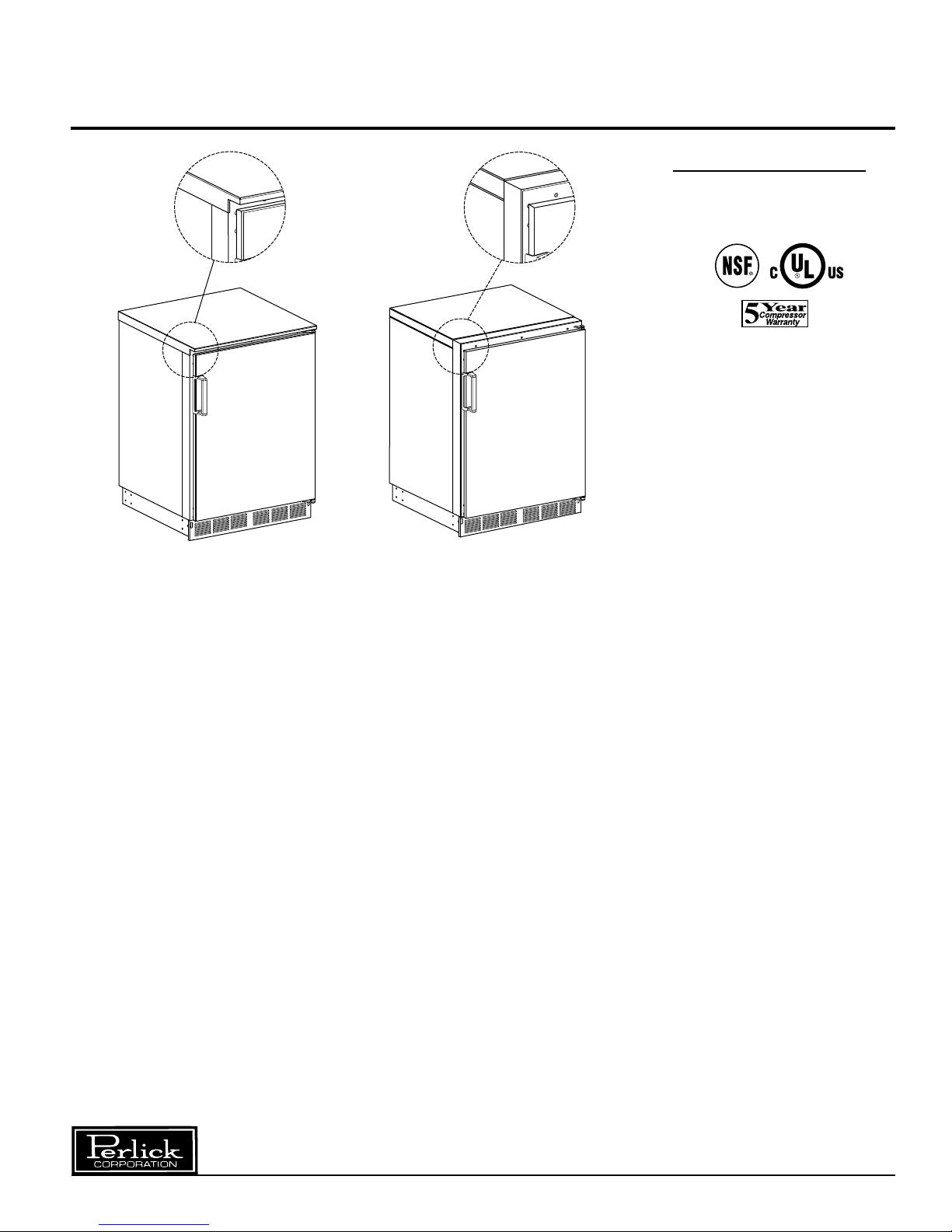
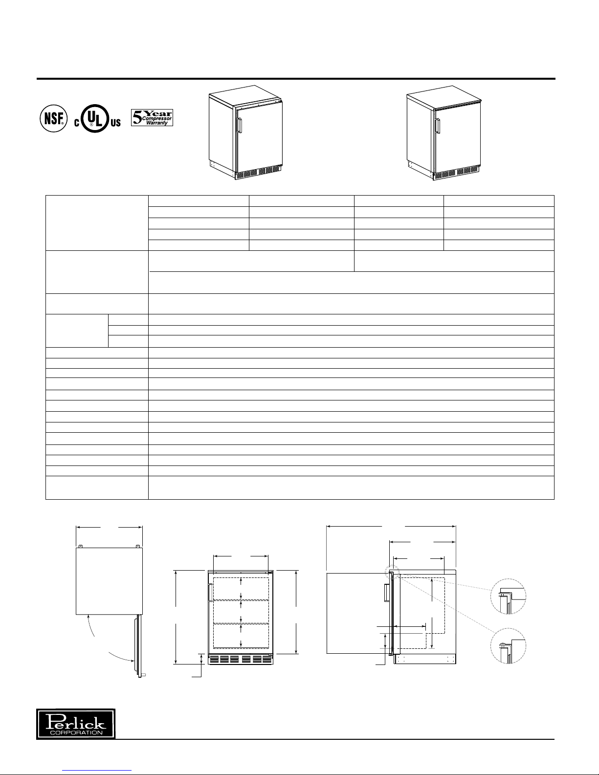
NON-FINISHED TOP FINISHED TOP
MODEL NOS. DOOR FINISH DOOR FINISH
R24NB Black R24SB Black
R24NS Stainless Steel R24SS Stainless Steel
R24NG Glass w/ Black Trim R24SG Glass w/ Black Trim
R24NT Glass w/ Stainless Trim R24ST Glass w/ Stainless Trim
EXTERIOR: Back, top and sides are Galvanized steel. Top and sides are stainless steel.
Back is galvanized steel.
Both models: Front is stainless steel. Doors: Either black vinyl CRS or stainless steel.
Bottom: galvanized steel with stainless grille.
INTERIOR Both models: Interior liner is stainless steel. Includes two adjustable vinyl coated shelves plus
a bottom shelf.
CABINET Length 24” (610)
DIMENSIONS Depth 24
(mm) Height 34
INTERIOR CU. FT. (m3) 4.9 (0.14)
SHELVING Bottom floor shelf and two additional shelves included
CASE CAPACITY* 4.6
CONDENSING UNIT H.P. 1/6 HP
RUNNING LOAD –AMPS 2.3
Ship Wt. Lbs. (kg.) 145 (54)
ELECTRICAL 1 1 5V, 60Hz., 1 phase . Furnished with 3-prong, 6 foot rubber plug in cord.
PLUMBING None required. Moisture drains to self evaporating condensate pan in machinery compartment.
INSULATION 2” foamed-in-place polyurethane insulation.
TEMPERATURE RANGE Adjustable from 32°F to +42° F (0° to 6° C).
REFRIGERATION R-134A capillary tube-type. with hermetic condensing unit. Front access for condenser and cleaning.
VENTILATION Front vented.
OPTIONAL • Set of 4 casters (3
ACCESSORIES & • Set of 4 adjustable legs (6” - 7
* Capacity calculations based on use of 12oz. export bottles on standard shelving.
3
⁄4” high) P/N 65426.
1
⁄4” high) P/N 65423.
1
⁄4” (615)
1
⁄2” (887)
24”
[610]
34 1/2”
[887]
180°
DOOR SWING
3 11/16”
[92]
Top View Front View End View
Perlick is committed to continuous improvement. Therefore, we reserve the right to change specifications without prior notice.
20”
[508]
8” [203]
8” [203]
8 7/16” [214]
30 9/16”
[776]
2
29 1/4”
[743]
11 3/4”
[470]
5 9/16”
[141]
47 1/8”
[1197]
24 1/4”
[615]
18 1/2”
[470]
25 3/4”
[654]
FINISHED
STAINLESS
TOP
NON-FINISHED
TOP
Form No. Z2288
Rev. 8.22.06
Page 3
Preparing the Cabinet – Single Door Refrigerator
Uncrating and Inspection
Remove all crating material before operating.
Carefully inspect cabinet for hidden damage.
If damage is discovered, file your claim immediately
with the transport company. Perlick is not
responsible for damage in transit.
Plumbing
No plumbing connections are required. Condensate
from the cooling coil is automatically evaporated
through a condensate pan located in the
condensing unit section.
Electrical
The cabinet must be connected to a separately
fused power source (see Electrical Specification
Plate) and grounded in accordance with National
and Local Electrical Codes.
CAUTION: Do not attempt to operate the equipment
on any other power source than that listed on the
Electrical Specification Plate.
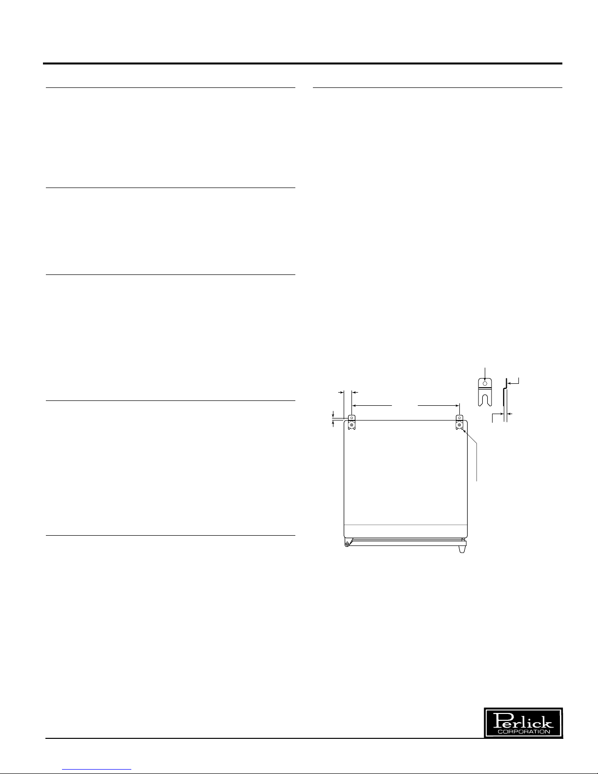
Anti-tip (without Legs or casters)
To prevent the cabinet from tipping forward and to
provide a stable installation, the cabinet must be
secured in place with an anti-tip device.
A set of metal anti-tip brackets and installation
screws (#10brackets should be attached to the floor, at the
back of the cabinet; each bracket located to catch
each rear leveling leg when the cabinet is pushed
backward into position.
THE ANTI-TIP BRACKETS MUST CATCH EACH
OF THE LEVELING LEGS TO HAVE ASTABLE
AND SAFE INSTALLATION.
Some installation sites might need to be modified to
provide a secure surface for attaching the bracket.
Refer to the illustration below for anti-tip mounting
bracket locations.
NOTE: Do not extend leveler leg
more than 3/4” out of base. Do not
shim or pad to obtain levelness.
3
” wood screws) are supplied. These
⁄4
Ø 3/8”
Surface
mounts
to floor.
Placing the Cabinet
To assure maximum performance, fresh air must
be allowed to circulate through the machinery
compartment. Do not place anything in front of the
cabinet that would obstruct air flow at these grilles.
Do not place the unit in an unventilated small room.
Cabinet should be leveled front to back and side
to side.
Installing Casters or Legs (optional)
Attach casters or legs to the mounting bracket with
lockwashers and
Attach bracket and leg/caster assembly to the side
of the cabinet base using the
tapping machine screws provided.
1
⁄4”–20 hex head nuts provided.
1
⁄4”–20 hex head self-
7/16”
1 1/2”
20 7/8”
Cabinet must
have at least
5/16” clearance
from floor to
accomodate
brackets.
Shown with leg
leveler engaged
in anti-tip bracket.
Perlick is committed to continuous improvement. Therefore, we reserve the right to change specifications without prior notice.
3
Form No. Z2288
Rev. 8.22.06
Page 4

Operation Instructions – Single Door Refrigerator
Sealing the Cabinet
For sanitation purposes, it may be necessary to
seal the base of the cabinet to the floor. This can be
accomplished by laying a bead of silicone sealant
between the base of the cabinet and the floor as
shown by the figure below.
When sealing the cabinet to the floor, make sure
that the louvered front grille plate can still be
removed for condenser maintenance and cleaning.
CABINET
BEAD SILICON
SEALER (RTV)
FLOOR
Temperature Control
An adjustable temperature control is located inside
the refrigerator on the evaporator fan panel
assembly. Approximate temperature operating
range: 32° F. minimum and 42° F.
maximum. Make adjustments as shown to attain
the desired
temperature.
Colder Temperatures: Turn the adjusting
■
screw clockwise (to the right).
■ Warmer Temperatures: Turn the adjusting
screw counterclockwise (to the left).
■ Temperature Control “OFF”: Turn the
adjusting screw completely counterclockwise to the “O” position until a click is noted.
The condenser fan and the evaporator fan
motor turns off and on with the compressor.
NORMAL
3
WARMER
4
6
7
COOLER
Cleaning the Cabinet:
■ Use a mild detergent and water to clean the
inside and outside of the cabinet. Dry
thoroughly. Never use a scouring pad or
abrasive cleanser.
NOTE: An industrial strength, commercial
cleaner can be used to clean the outside of
painted cabinets
Cleaning the Condenser:
■ Use a long handled, stiff brush to clean dirt
from the front surface of the condenser.
Keeping the condenser free from dust and
dirt will ensure efficient operation.
CAUTION: Do not bend the fins while
brushing the front of the condenser..
2
1
05
CONDENSING UNIT
8
9
Avoiding Stainless Steel Corrosion
Corrosion can be prevented by following product
cautions, cleaning instructions and avoiding use
of certain chemicals or objects which will cause
stainless steel corrosion.
STAINLESS STEEL ENEMY
■ Steel wool or steel scouring pads
■ Cherry/Orange/Olive juice
■ Chlorine Bleach
■ Sharp Objects
Perlick is committed to continuous improvement. Therefore, we reserve the right to change specifications without prior notice.
4
Form No. Z2288
Rev. 8.22.06
Page 5

Replacement Parts – Single Door Refrigerator
21
13
10 11
14
12
19
17
16
15
6
22
CAUTION
1
22
32
4
5
24
20
18
23
9
7
8
■ Service should be done by a qualified
refrigeration technician.
■ Disconnect all power before servicing
the cabinet.
Perlick is committed to continuous improvement. Therefore, we reserve the right to change specifications without prior notice.
5
Form No. Z2288
Rev. 8.22.06
Page 6

Replacement Parts – Single Door Refrigerator
MODEL NOS. ALL MODELS
Item Description Part Numbers
1 Compressor for R134A 63778
2 Condenser fan motor C15239A
3 Condenser fan motor bracket 60988-1
4 Condenser fan blade C22370
5 Condenser fan shroud 65206-2
6 Rear panel 65159-1
7 Front grille 65158-1
8 Condenser coil 65252
9 Condenser pan 65473
10 Evaporator fan guard 65254
11 Evaporator fan motor 65253
12 Evaporator assembly, complete H66136R
13 Top overlay 65429-1SS
14 Temperature control with dial plate 61271
15 Door assembly 66223
16 Magnetic door gasket 66237-1
17 Shelf 66236-1
18 Shelf, bottom 64809-1
19 Pilaster C19271
20 Shelf clip C15875
21 Evaporator grille 66139-2
22 Tip over bracket 63740
23 Door handle C31409-1
24 Leg kit set of 4 includes brackets 65423
25 Caster kit set of 4 including brackets (not shown) 65426
26 Complete hinge set-left (not shown) 66246L
27 Complete hinge set-right (not shown) 66246R
29 Power cord wiring harness (not shown) 65531
30 Evaporator assembly wiring harness (not shown) 65532
31 Evaporator fan motor wire harness (not shown) 65271
Perlick is committed to continuous improvement. Therefore, we reserve the right to change specifications without prior notice.
6
Form No. Z2288
Rev. 8.22.06
Page 7

Wiring Diagram – Single Door Refrigerator
JUNCTION
POINTS
JUNCTION
POINTS
BLUE
WHITE
BLACK
EVAPORATOR FAN
THERMOSTAT
POWER CONNECTION
NEMA-15P CORD
BLACK
WHITE
GREEN
BLACK
WHITE
RED
RED
RED
WHITE
GREEN
BLUE
RED
WHITE
JUNCTION
POINTS
CONDENSER FAN
COMPRESSOR
OVERLOAD
RELAY
END VIEW
Perlick is committed to continuous improvement. Therefore, we reserve the right to change specifications without prior notice.
7
Form No. Z2288
Rev. 8.22.06
Page 8

Door Switching Instructions – Single Door Refrigerator
Tools Required
■
Large Flathead Screwdriver.
■
Regular Philips-head screwdriver.
■
Small Philips-head screwdriver
Left Hinged Door
Units are available from
factory mounted left or right.
Workboard units are available with left mounting only.
All doors may be changed by
customer.
Operations to Perform
STEP 1
STEP 5
STEP 4
STEP 1:
Remove top hinge pin from assembly.
Carefully lift and tilt out door assembly
from the unit and set aside.
STEP 2
STEP 3
NOTE: Changing
the door mount is
not advised if you
have a custom
wood overlay.
This may result in
having a handle
in an undesirable
location.
HINGE PIN
STEP 4:
Remove bottom hinge bracket to
HINGE
BRACKET
allow you to remove the door closing
insert. Immediately replace hinge
bracket.
CLOSING
INSERT
STEP 5:
Remove top hinge bracket to allow
assembly of door closing insert
removed in step 4. reassemble hinge
to door after installing the closing
insert.
Operation Notes
NOTE 1:
NOTE 4
Lower left hinge
bracket rotates
180° and
becomes upper
right hinge
bracket.
NOTE 2 & 3:
HINGE
BRACKET
NOTE 1
NOTE 2
NOTE 3
NOTE 5
STEP 2:
Carefully remove hole plugs on right
side of unit. be careful not to
scratch unit. Top and bottom plugs
must be removed. Do not discard.
HINGE
BRACKET
CLOSING
INSERT
BOTTOM
HINGE PIN
HOLE
PLUGS
DOOR
CLOSING
INSERT
STEP 3:
Remove top and bottom hinge brackets from unit. Then
remove door closing insert and hinge pin from bottom
hinge bracket. See door bottom hinge assembly detail.
8300 West Good Hope Road • Milwaukee, WI 53223 • Phone 414-353-7060 • Fax 414-353-7069
Toll Free 800-558-5592 • E-Mail: Perlick@Perlick.com • www.Perlick.com
Perlick is committed to continuous improvement. Therefore, we reserve the right to change specifications without prior notice.
DOOR
HINGE
BRACKET
BRACKET
HINGE
PIN
UNIT
HINGE
Top left hinge bracket rotates 180°
and becomes bottom right hinge
bracket.
Bottom hinge pin and door closing
insert assemble to bottom right hinge
bracket.
NOTE 4: The hole plugs removed
earlier are to be inserted into the
vacant left door mounting holes. Do
not hit with hammer or damage may
occur. Use hammer handle or wood
block to push plugs into holes.
NOTE 5:
Door bottom on right mounted version was door top on
left mounted version. Before attempting to re-mount door
verify that: (1) The door handle will be on the outside of
door. (2) The door closing inserts are on the bottom. (3)
All screws are hand tightened, over tightening will damage the unit.
Form No. Z2288
Rev. 8.22.06
 Loading...