

Page 1
INSTALLATION AND OPERATION INSTRUCTIONS
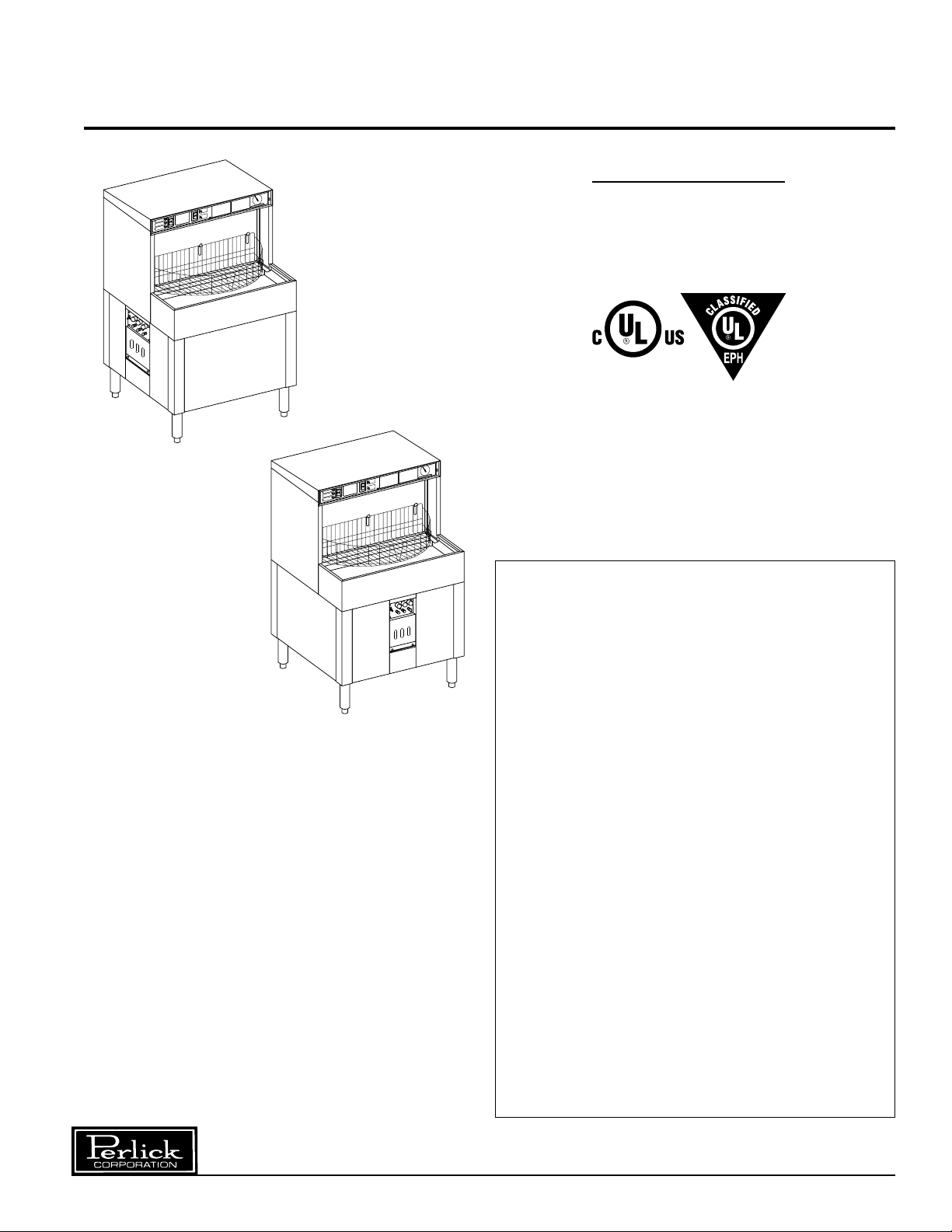
PERLICK BATCH ROTARY GLASSWASHERS
MODEL NOS.
■■ PKBR24
■■ PKBR24L
■■ PKBR24R
PKBR24L
PKBR24
IMPORTANT INFORMATION
This manual has been prepared to assist you in the
operation of the Perlick Batch Rotary Glasswasher.
We dedicate considerable time to ensure that our
products provide the highest level of customer
satisfaction. If service is required, your dealer can
provide you with a list of qualified service agents. For
your own protection, never return merchandise for
credit without our approval.
We thank you for selecting a Perlick product and
assure you of our continuing interest in your
satisfaction.
Table of Contents
Warranty Information.........................................2
Specifications.....................................................3
Chemical Specifications
Water Conditioning ..............................................4
Chemical Concentrations.....................................4
Start-Up Procedures
Before Starting the Glasswasher.........................5
Starting the Glasswasher.....................................5
Priming the Chemical System..............................5
Operational Testing..............................................5
Installing Chemical Squeeze Tubes.....................6
Priming the Chemical Pumps ..............................7
Setting the Chemical Controls.............................7
Owners Instructions
Component Identification.....................................8
Instrument Panel..................................................9
Operating the Glasswasher.................................9
Washing Glasses.................................................9
Chemical Control Panel.....................................10
Maintenance and Troubleshooting
End of Day Shutdown........................................11
Deliming .............................................................11
Troubleshooting..................................................11
Machine Operation & Cycle Sequence..............12
Replacement Parts ............................................13
Electrical Connection Diagram ..........................14
Adjusting Chemical Concentrations ...................15
Calibrating the Chemical System.......................15
8300 West Good Hope Road • Milwaukee, WI 53223 • Phone 414-353-7060 • Fax 414-353-7069
Toll Free 800-558-5592 • E-Mail: Perlick@Perlick.com • www.Perlick.com
Page 2

Warranty Information
ONE YEAR LIMITED WARRANTY
The Perlick Corporation warrants its glasswasher to
be free from defects in material and workmanship,
under normal use and operation, for a period of one
(1) year from the date of initial start-up or eighteen
(18) months from the date of shipment from the
®
factory, whichever comes first. Perlick
will repair or
replace, at our option, during the warranty period, any
part that may be defective in material and/or
factory workmanship. This warranty is conditioned
upon the customer's maintenance and care as
outlined in the service manual and the return of the
warranty registration card. Warranty repairs will
be performed, free of charge, during Perlick's
®
authorized service agency's normal business hours.
Should the customer require after hours service,
it is the customer's responsibility for any overtime
premium. Machine is warranted only for the
initial place of installation. Removal of machine
automatically terminates this warranty.
®
Perlick
shall have no liability under this warranty
unless the customer promptly notifies Perlick®or its
factory authorized service agent of any alleged
defects. All defective parts become the property of
®
Perlick
at Perlick's
and must be returned to Perlick®, or its agent,
®
expense, within thirty (30) days from the
date of the part's replacement. Parts replaced within
the warranty carry only the unexpired portions of the
machine's warranty. Not covered by this warranty
are changes (parts and/or labor) necessitated by or
damage resulting from: water conditions, accident,
alteration, improper use, abuse, tampering, improper
installation or failure to follow operating and
maintenance procedures. Examples of the foregoing,
but without limitations are:
1) Damage to machine resulting from excessive
concentrations of chlorine or deliming acid solutions;
2) Use with utilities other than designated on the
glasswasher I.D. plate or owners manual;
3) Improper connection of utility services;
4) Inadequate or excessive water pressure; 5) Leaks
caused by faulty installation; 6) Component failures
caused by water leaks due to faulty installation; 7)
Failure to comply to national and/or local codes; 8)
Failure due to deposits resulting from hard water,
detergents, chlorines, delimers, or improper maintaining, 9) Resetting breakers or fuse replacement;
10) Adjustments such as thermostats and chemical
pump system; 11) Improper opening of utility supply
valve; 12) Cleaning drain valves, line strainer, spray
nozzles, etc.; 13) Improper installation or malfunction
of chemical dispensing equipment supplied by
others; 14) Failure to provide regular and/or daily
maintenance and cleaning as outlined in this owners
manual.
THIS WARRANTY IS LIMITED TO GLASSWASHERS INSTALLED WITHIN THE 48 CONTINENTAL
UNITED STATES AND CANADA. IN ALASKA,
HAWAII AND ELSEWHERE OUTSIDE THE
CONTINENTAL U.S. AND CANADA, THIS
WARRANTY IS LIMITED TO REPLACEMENT
PARTS ONLY.
THERE ARE NO OTHER WARRANTIES,
EXPRESSED OR IMPLIED, MADE BY THE
PERLICK CORPORATION FOR ITS GLASSWASHER, INCLUDING ANY IMPLIED WARRANTY OF
MERCHANTABILITY OR FITNESS FOR A
PARTICULAR PURPOSE AND IN LIEU OF ALL
OTHER OBLIGATIONS OR LIABILITY ON THE
®
PART OF PERLICK
, INCLUDING LIABILITY FOR
INCIDENTAL OR CONSEQUENTIAL DAMAGES
OR FOR LOSS OF PROFITS OR GOODWILL. NO
OTHER WARRANTIES ARE AUTHORIZED ON
®
BEHALF OF PERLICK
.
RECORD THIS INFORMATION
MODEL NO.__________________________________________________
SERIAL NO.._________________________________________________
INSTALLATION DATE:_________________________________________
Perlick is committed to continuous improvement. Therefore, we reserve the right to change specifications without prior notice.
2
Page 3
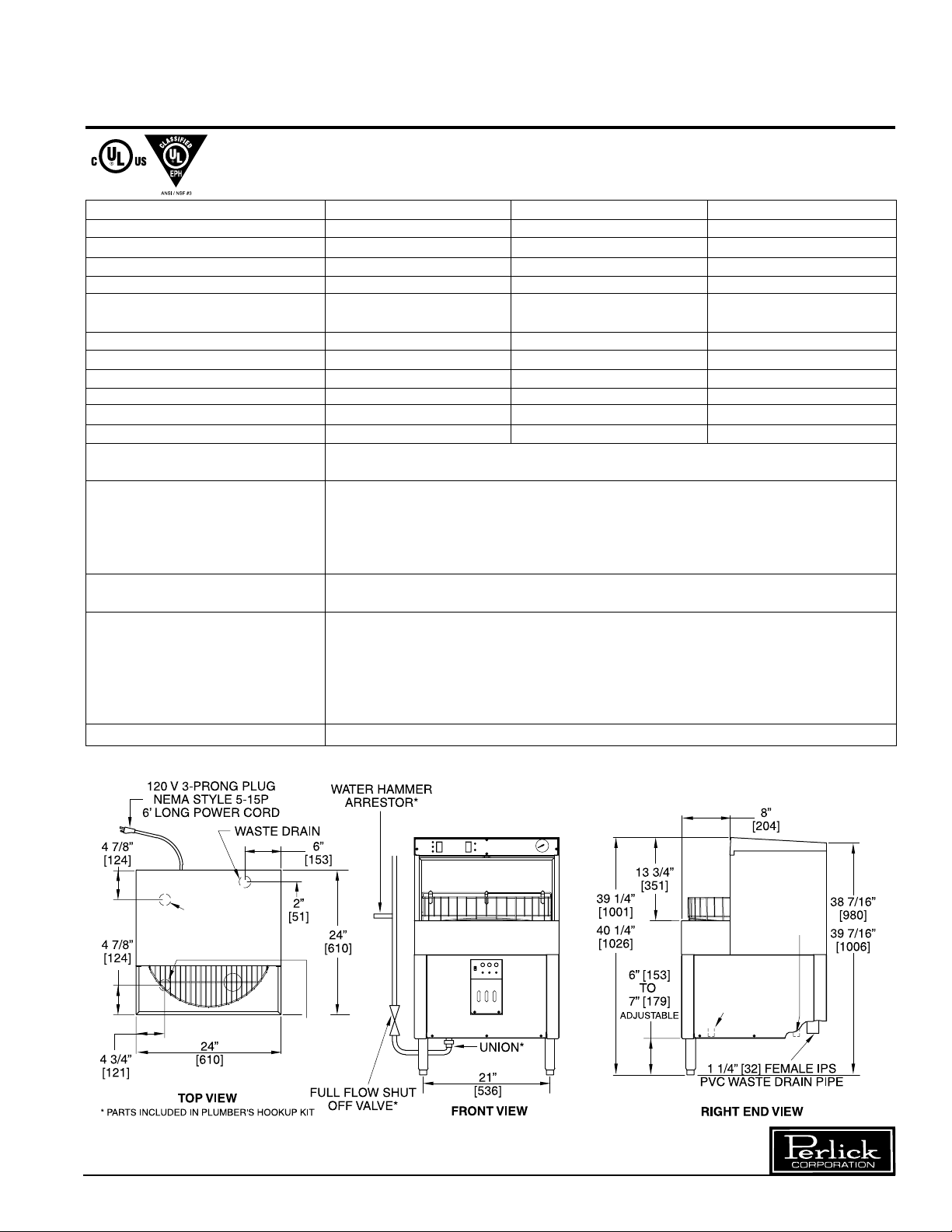
Sizes and Specifications
PKBR24 Glasswashers
MODEL NOS. PKBR24 PKBR24L PKBR24R
WASH TANK CAPACITY (gals.) 1 1 1
CYCLE TIME (sec.) 120 120 120
WASH TIME (sec.) 60 60 60
SANITIZER TIME (sec.) 35 35 35
GLASSES WASHED PER
1
HR. (2
/2” dia.)
TANK HEATER (watts) 650 650 650
WASH PUMP CAPACITY (gals./min.) 24 24 24
DRAIN FLOW (gals/cycle) 1.67 1.67 1.67
EXHAUST REQUIREMENT None None None
MAXIMUM GLASS HEIGHT 10” 10” 10”
SHIP WT lbs. (kg) 225 (103) 225 (103) 225 (103)
ELECTRICAL 120 Volt, 60 Hz., single phase AC. 5.4 amps, furnished with 6 foot power cord and standard
3 prong NEMA style 5-15P.
PLUMBING Hot Water Inlet Connection:
flow rate of 4.0 gal/min. Drain: 1
Hookup Kit: Includes water hammer arrestor, stop valve and union.
the Glasswasher with Plumbers Hookup Kit can damage the hot water solenoid valve. Machine
failure due to improper installation is not covered by Perlick’s warranty.
WATER HARDNESS Water containing more than 15 GPG will require a water softener.
caused by hard water are not covered under Perlick’s warranty.
DETERGENT, SANITIZER and Detergent: Aheavy-duty liquid warewashing detergent containing water conditioners.
RINSE AID Chlorine Sanitizer:Any EPAregistered chlorine can be used. The EP Amarking can be found on
the container label. Rinse Aid: A low-foaming warewashing rinse aid containing water conditioners.
Note: To ensure maximum glasswasher performance. It is important to select the appropriate
detergent and rinse aid for specific water conditions. These chemicals can be purchased from a
local chemical supplier or food service distributor.
OPTIONALACCESSORIES • Low Sanitizer shut down kit - #61945 • Glass Rack - #50470-2
All plumbing and chemical lines must be routed so that the glasswasher can be pulled out for service.
720 720 720
1
/2” NPTM. Incoming Hot Water: 130–140° F, at 30-60 psi with a
1
/4 IPS PVCsocket connection to include an air gap. Plumbers
Important: Failure to install
Caution: Parts
failure
HOT W ATER INLET
1/2” [13] MALE N.P.T.
(L.H. UNITS)
HOT W ATER
INLET 1/2” [13]
MALE N.P.T.
(R.H. & STD.
UNITS)
Perlick is committed to continuous improvement. Therefore, we reserve the right to change specifications without prior notice.
3
HOT W ATER
INLET 1/2” [13]
MALE N.P.T.
(L.H. UNITS)
HOT W ATER
INLET 1/2” [13]
MALE N.P.T.
(R.H. & STD.
UNITS)
Page 4

Chemical Specifications
Water Conditioning
■ If the water you will use in the glasswasher is
too hard, the glasswasher will not clean and
sanitize glasses properly. Water contains
dissolved calcium/lime which makes water
"hard." Water can be conditioned mechanically
by using a water softener or chemically by
using a detergent and rinse aid which contains
water conditioners. If the water you will use in
the glasswasher is not properly conditioned,
the glasswasher will:
■ Require frequent deliming,
■ Cost more to operate (higher chemical usage),
■ Shorten machine life.
Water Hardness Type of Water
GPG (Grains Per Gallon) Treatment required
0 - 5 GPG Chemicals containing
Low water conditioners
6 - 10 GPG Chemicals containing
Medium water
conditioners
11 - 15 GPG Chemicals containing
High water conditioners
Chemical Specifications
DETERGENT:
Heavy-duty, liquid warewashing detergent with
water conditioners.
SANITIZER (CHLORINE):
EPA registered, non-foaming liquid chlorine.
RINSE ADDITIVE:
Low-foaming, warewashing rinse additive.
Chemical Concentrations
DETERGENT
Start the glasswasher and wait for 30 seconds into
the wash cycle. Then stop the machine; take a
sample and test for active alkalinity. It should be
250 ppm. +10%.
SANITIZER
Run the glasswasher through a complete cycle.
Take a sample and test it for chlorine concentration. It should be 50 ppm. minimum.
RINSE ADDITIVE
There is no minimum concentration. Visually check
the glassware for satisfactory wetting.
15 GPG Plus Water softener required
and chemicals
containing Low water
conditioners
Water with more than 15 GPG will require a water
softener. It cannot be conditioned economically
with chemicals. Failure of parts caused by hard
water are not covered under the warranty.
Perlick is committed to continuous improvement. Therefore, we reserve the right to change specifications without prior notice.
4
Page 5

START UP PROCEDURES
IMPORTANT
When an indicated function does not occur, corrections MUST be made before proceeding. No steps
in a procedure should be ignored or omitted.
BEFORE STARTING THE GLASSWASHER
CHECK TO DETERMINE IF...
■ Water and Power are ON to glasswasher.
■ Chemical System Power Switch is ON.
■ Chemicals (detergent, sanitizer, and rinse
aid) have been purchased and are on site
for use.
■ Chemical line drop tubes are in appropriate
containers:
■ RED line into the detergent container.
■ WHITE line into the sanitizer container.
■ BLUE line into the rinse additive
container.
REMOVE...
■ All protective paper from the front of
machine.
■ Shipping block from under the lower spray
arm.
INSTALL...
■ Both glass racks onto the divider.
PRIMING THE CHEMICAL SYSTEM
The chemical system prime buttons are located in
the chemical control panel. Each of the three
chemical systems must be primed separately.
■ Press the prime button until the chemical is
observed in the flow indicator window.
■ Continue to press the prime button for an
additional 15 seconds to complete the
priming.
■ Repeat procedure until all three systems
have been primed.
OPERA TIONAL TESTING
PRESS
■ Wash switch to run the glasswasher
through a complete cycle.
CHECK
■ That only the power and washing lights are
illuminated while the machine is washing.
■ That only the power and cycle complete
lights are illuminated when cycle is finished.
■ That the cycle complete light goes out
when divider is rotated.
STARTING THE GLASSWASHER
PLACE...
■ Power/drain (on-off drain) switch to ON.
CHECK...
■ Water level inside the tank (Level should be
at top of overflow tube.)
Perlick is committed to continuous improvement. Therefore, we reserve the right to change specifications without prior notice.
5
Page 6

START UP PROCEDURES
INSTALLING THE CHEMICAL
SQUEEZE TUBES
When an indicated function does not occur, corrections MUST be made before proceeding. No steps
in a procedure should be ignored or omitted.
IMPORT ANT
The detergent, sanitizer, and rinse aid squeeze
tubes must be installed before operating the
glasswasher. Glassware will not be properly
washed or sanitized unless these tubes are
installed.
1. Remove the front panel and the chemical
control panel, exposing the three chemical
pumps.
2. Confirm water and power are on.
3. Place power switch to ON. Glasswasher
fills for 25 seconds.
4. IMPORTANT: Install squeeze tubes, one at
a time, to avoid possible mixing of
components during reassembly. Although
the components appear to be identical,
they are not. If the entire housing is
removed, it must be reinstalled in exactly
the same position to avoid stripping
the spider.
5. Remove 4 nylon nuts from pump
head. To remove the pump cover
without removing the entire
assembly, place a finger on the spider and
pull the cover straight off of the four
mounting studs.
Note: The roller has A & B engraved on its interior.
It has also been color coded on the spider. Confirm
the following:
Red ....A Position...Detergent ...................Left Pump
White..APosition...Sanitizer (Chlorine) ...Middle Pump
Blue....B Position...Rinse Aid....................Right Pump
6. Press the tube between the roller and
housing. Caution: Using tools to push the
squeeze tube in can result in damage to
the tube. To make squeeze tube installation
easier, use the prime button to rotate roller.
7. Replace the pump cover and nuts making
sure pump cover is locked in position.
8. Repeat procedure for the two remaining
pumps and replace the chemical control
panel and front panel.
DETERGENT (RED)
Perlick is committed to continuous improvement. Therefore, we reserve the right to change specifications without prior notice.
6
Page 7

START UP PROCEDURES
PRIMING THE CHEMICAL PUMPS
Place the chemical, detergent, chlorine,
and rinse aid containers in a convenient
location. Place appropriate drop tube into
corresponding container as labeled on the
drop tube.
■ Red Line.......Detergent Container
■ White Line ....Sanitizer Container
■ Blue Line ......Rinse Aid
Press and hold detergent prime button.
Window will illuminate so that chemical flow
can be observed. When chemical is observed,
hold for an additional 15 seconds. This will
allow the chemical to reach the wash tank
area. Repeat procedure for Sanitizer and
Rinse Aid.
SETTING THE CHEMICAL CONTROLS
2. DETERGENT CONTROL
Controls detergent concentration with
three pre-calibrated settings:
1 = Lowest Concentration
2 = Medium Concentration
3 = Highest Concentration
Your water hardness, detergent strength and
amount of water conditioners in the detergent
will determine the final setting of this control.
Start with the control on No. 1 and increase
until the best cleaning result is achieved.
3. SANITIZER CONTROL
Controls chlorine concentration with an
infinite adjustment. This control is set so
that a minimum of 50 ppm. of chlorine is
obtained. Use the chlorine test kit to set
this control provided with the glasswasher.
NOTE: This setting should be tested daily
and must be adjusted according to local
health standards.
1. CHEMICAL SWITCH
This switch turns the chemical pump
system on and off and will be used to
delime the machine. The switch
should be in the ON position.
4. RINSE AID
Controls rinse aid concentration with three
pre-calibrated settings:
1 = Lowest Concentration
2 = Medium Concentration
3 = Highest Concentration
Your water hardness and the strength of the
rinse aid used will determine the final setting
of this control. Start with the control in the
No. 1 position. If the water does not sheet on
the glassware, and droplets are present,
increase the concentration.
Perlick is committed to continuous improvement. Therefore, we reserve the right to change specifications without prior notice.
7
Page 8

OWNERS INSTRUCTIONS
COMPONENT IDENTIFICATION
1 - LOWER SPRAY ARM:
Oscillates 120° to enable the fan-shaped
spray to thoroughly clean and sanitize the
interior of the glasses.
2 - TANK COVER SCREEN:
Located at the bottom of the wash area.
Care should be taken to keep debris from
entering the tank when the screen has
been removed for cleaning.
3 - OVERFLOW TUBE:
Located in the wash tank. Drains overflow
water.
4 - TANK FILTER:
Located within the tank. Care should be
taken to keep debris from entering the
wash system when the filter is removed
for cleaning.
8 - CHEMICAL CONTROL PANEL:
Located on the front panel. This panel
contains all the user controls for the
chemical system.
■ Chemical control knobs control the
chemical concentrations in the wash
water
■ The prime buttons allow the chemical
lines to fill without having to run the
glass washer.
■ The chemical system power switch
should be kept on during normal
operation. This switch is turned off while
the glasswasher is cleaned.
9 - GLASS RACK(S)
10 - INSTRUMENT PANEL
5 - UPPER SPRAY ARM:
A stationary arm located at the top of the
wash compartment. The fan shaped
spray cleans and rinses the exterior of the
glasses.
6 - DIVIDER:
Holds two removable racks. The divider
can be manually rotated in either direction,
but must be parallel to the front of the
machine before a wash cycle can begin.
If the divider is rotated during a wash cycle,
the machine will stop.
7 - CHEMICAL FLOW INDICATORS:
Located just below the chemical control
panel. These windows illuminate while the
chemical pumps operate, providing a visual
indicator of the chemical flow.
Perlick is committed to continuous improvement. Therefore, we reserve the right to change specifications without prior notice.
8
Page 9

START UP PROCEDURES
THE INSTRUMENT PANEL
8
WASH
Item No. Description Function
1 POWER/DRAIN (On/Off Drain) The Power/drain (on/off drain) switch is a three-
* Note: Switch must be pressed for a
minimum of ten seconds to drain the
tank. The drain is activated for only as
long as the switch is pressed.
2 CHEMICALS OFF LIGHT Illuminated when the switch in the chemical control
3 LOW WATER LIGHT Steady Illumination: Machine has stopped due to low
4 POWER ON LIGHT Illuminated when the power is ON.
5 WASH SWITCH Initiates a wash cycle when pressed.
6 CYCLE COMPLETE LIGHT Illuminated when the wash cycle is complete and divider is
7 WASHING LIGHT Illuminated when the machine is in the wash cycle.
8 THERMOMETER Indicates water temperature inside tank. Operating
position rocker switch.
Center position: Power is OFF; no lights are illuminated.
Upper position: Power is ON and Power ON light is
illuminated. Opens hot water solenoid for 25 seconds.
Lower position: Machine is in the DRAIN* mode.
panel is in the OFF position.
water in tank.
Flashing: Drain failure.
ready to be rotated.
temperature should be 130-140° F.
OPERATING THE GLASSWASHER
1. Water temperature (No. 8) should be between
130-140° F. to assure proper glass washing.
Open a hot water faucet in the bar area to
ensure that adequate hot water is coming to the
glasswasher.
2. Press Power Switch (No.1.) Yellow Power On
Light (No. 4) comes on and wash tank fills with
water for 25 seconds. If the red Low Water Light
comes on, this indicates that incoming water
pressure or flow is not adequate. Contact Perlick
or your authorized service agency.
WASHING GLASSES
1. The glasswasher is provided with two vinyl-coated
racks which hang on each side of the divider.
Racks are removable for easy loading and
unloading of glassware.
2. Place EMPTY glasses on glass rack, open end
down. (Maximum glass size is 10".) Solids which
are dumped into the glasswasher (i.e., napkins,
straws, sticks, fruit rinds, etc.) will significantly
affect the glasswasher's performance and time
needed for daily cleaning. Poor performance due
to poor cleaning is not covered by manufacturer's
warranty .
3. Rotate loaded rack 180° into the wash area.
4. Depress Wash Switch (No. 5.) the yellow
Washing Light (No. 7) comes on initiating a two
minute wash cycle. Never rotate divider until
Cycle Complete light is illumnated. This action
terminates the wash cycle and then the glassware
will not have been properly washed and/or
sanitized.
5. When the yellow Cycle Complete light comes on,
this indicates that the glasses in the wash area
have been washed and sanitized. Rotate the
divider 180 degrees to gain access to clean
glasses. Yellow Cycle Complete light will go
off and the next load of dirty glasses is ready
to be washed.
6. Drain excess water from glass sumps by lifting
the front edge of the glass rack.
Perlick is committed to continuous improvement. Therefore, we reserve the right to change specifications without prior notice.
9
Page 10

OWNERS INSTRUCTIONS
DETERGENT
CALIBRATING THE CHEMICAL SYSTEM
RINSE AID
Detergent and Rinse Additive:
Low Foaming Liquid
Position 1: Low soil and soft water
Position 2: Medium soil and soft water
Position 3: High soil and hard water
TO PRIME:
Depress buttons until chemicals appear in windows.
Sanitizer:
Adjust to min. 50 ppm chlorine
(see Test Kit Instructions)
EPA Registered
Non–Foaming Liquid
Alkaline
Non–Chlorinated
Low Foaming Liquid
CHLORINE
PRIME PRIME PRIME
ON
33
1
+
_
22
OFF
CHEMICAL
SWITCH
DETERGENT RINSE AIDSANITIZER
CHEMICAL CONTROL PANEL
Item No. Description Function
1 CHEMCIAL SYSTEM Should be kept in the ON position except during cleaning.
POWER SWITCH When switch is in the OFF position, the Chemical OFF
light on the instrument panel will be illuminated.
2 DETERGENT CONTROL KNOB Controls detergent concentration with three, pre-calibrated
settings:
1 = Lowest Concentration
2 = Medium Concentration
3 = Highest Concentration
3 SANITIZER CONTROL KNOB Controls sanitizer concentration with an infinite adjustment
to precisely dispense sanitizer to the required minimum of
50 ppm.
4 RINSE ADDITIVE CONTROL Controls rinse aid concentration with three, pre-calibrated
settings:
1 = Lowest Concentration
2 = Medium Concentration
3 = Highest Concentration
5 PRIME SWITCHES Fills chemical lines without running glasswasher. Power
ON light must be illuminated.
6 CHEMICAL FLOW INDICATORS These windows illuminate when a chemical is flowing
during a wash cycle or when chemical lines are being
primed, providing a visual indicator of chemical flow.
Perlick is committed to continuous improvement. Therefore, we reserve the right to change specifications without prior notice.
10
Page 11

MAINTENANCE AND TROUBLESHOOTING
END OF DAY SHUTDOWN
Clear glassware from racks. Press lower portion of
Power/Drain (on-off drain) switch for ten (10) seconds to drain tank. Place Power/drain (on-off drain)
switch to off. We recommend that solid wastes be
removed from the load and unload area at least
once each day to ensure optimum performance.
DEMLING
Prolonged hard water use may cause a white film
to appear on the inside surface of the wash area. It
is then necessary to delime the machine.
1. Remove all glassware from racks, and any
debris from the load and wash areas.
2. Chemically charged water must be drained
from the tank. Press the lower portion of
Power/drain (on-off drain) switch for 10
seconds.
3. Place the chemical system Power Switch
to OFF.
4. Refill the tank by placing the Power/drain
(on-off drain) switch to ON. (Power ON and
chemical OFF lights illuminate.)
5. Add delimer to wash area. Use amount
recommended on container.
6. Press Wash Switch. (Washing light does not
illuminate in cleaning mode.)
7. While the machine is running, clean the load
area and exterior of the machine with a damp
cloth and wipe dry. Replenish chemicals if
required. See warning!
8. Press the lower portion of Power/drain
(on-off drain) switch for 10 seconds to
drain tank.
9. To restore service, place chemical Power
Switch to ON.
10. Place Power/drain (on-off drain) switch to
ON. The glasswasher is now ready to use.
WARNING
Always protect skin, eyes, and mucous membranes when working with chemicals. Always
clean up chemical spills immediately. At full
strength the chemicals used in your glasswasher
can cause severe burns and metal corrosion. Do
not mix with anything but water. Never intermix one
with the other. Hazardous vapors may result. Keep
out of the reach of children. See manufacturers
label for complete instructions.
TROUBLESHOOTING
SYMPTOM PROBABLE CAUSE
Machine Does Circuit breaker tripped.
Not Operate Power/drain (on-off drain) switch off.
Divider not parallel with front of
glasswasher. Water supply turned off.
Electrical cord unplugged.
Glasses Not Incoming water temperature too low.
Clean (Required water temperature 130-
140° F.) Detergent setting too low.
Tank filter plugged.
Machine Shuts Water supply turned off.
Down (Low Water Light On) Incoming water
supply insufficient. (4 gallon per
minute flow rate required.)
Flashing Low This indicates a drain failure.
Water Light Call your service agency.
Perlick is committed to continuous improvement. Therefore, we reserve the right to change specifications without prior notice.
11
Page 12

MAINTENANCE AND TROUBLESHOOTING
MACHINE OPERATION & CYCLE
SEQUENCE
At the beginning of the wash cycle, the water in
the tank is charged with detergent. After the cycle
is completed, the detergent water is dumped down
the drain. The sanitizing rinse cycle begins as the
tank is refilled with fresh water. Sanitizer and rinse
additive is pumped into the tank. The rinse water
is retained and will be used in the next wash cycle.
35 SECONDS
Perlick is committed to continuous improvement. Therefore, we reserve the right to change specifications without prior notice.
12
Page 13

MAINTENANCE AND TROUBLESHOOTING
REPLACEMENT PARTS
Item
No. Description Part No.
1 Glasswasher Control Kit 55042
2 Spray arm drive motor 52536
3 Wash pump 50445
4 Pump motor capacitor 52528
5 Water inlet valve 52652-1
6 Band heater 52669-1
7 Rinse aid pickup tube assembly 52626A-B
Detergent pickup tube assembly 52626A-R
Sanitizer pickup tube assembly 52626A-W
8 Divider side seal 52696
9 Wash water level switch R54978-1
10 Start/Wash switch 55003-1
11 Power/drain (on/off/drain) switch 55004-1
12 Red light 54809
13 Amber light 54810
14 Wash tank filter 52492
15 Safety switch - .250" quick connect 54995-1
16Safety switch - .187" quick connect 54996-1
17Roller bearing for divider lock C12698-1
Item
No. Description Part No.
18 Glass rack 50470-2
19 Top divider seal 52692
20 Top wash tank screen 50588
(For Serial Nos. to 443593 only)
20A Top wash tank screen R50614
21 Chemical system control board 50453
22 Drain valve 50451
23 Chemical system sight tube kit 52714A
24 Transformer 52566A
25 Temperature control 54153A
26 Fuse holder 54938-1
12 amp fuse 54939-1
27 Chemical pump gear motor 52537
PARTS NOT SHOWN
Chemical bulkhead fittings R54976
Amber chemical sight tube light 54790
Flat strainer 54965-1
Clean-out plugs for spray arms R54900-1
1
⁄4" ID. chemical pump squeeze tube 52679-1
3
⁄16" ID chemical pump squeeze tube 52681-1
1
⁄8" ID chemical pump squeeze tube 52680-1
Seal kit R54965
Perlick is committed to continuous improvement. Therefore, we reserve the right to change specifications without prior notice.
13
Page 14

1
WHITE
BLACK
15
9
10
8
CHEMICAL
SYSTEM
POWER
SWITCH
CHEMICAL SYSTEM
LIGHTS WIRE HARNESS
SIGHT GLASS LIGHTS
ELECTRICAL CONNECTION DIAGRAM
CHEMICAL SYSTEM CONTROL PANEL
2
1
5 VDC
DETERGENT
SELECT
SWITCH
DETERGENT
3
PRIME
SWITCH
2
5 VDC
1
SANITIZER
SPEED
CONTROL
5 VDC5 VDC24 VDC
SANITIZER
PRIME
SWITCH
RINSE AID
SELECT
SWITCH
2
3
RINSE AID
PRIME
SWITCH
14
1
5 VDC
13
4
3
15
5
7
5 VDC
12
11
CHEMICAL SYSTEM
WIRE HARNESS
3
6
9
121510
6
5 VDC
SAFETY
SWITCH
POWER
1
4
7
13
GROUND
WASHING
LIGHT
START
SWITCH
CYCLE
COMPLETE
LIGHT
5 VDC
INSTRUMENT PANEL
669
5
7
88888884
TERMINAL BLOCK
7
1
5
9
2
3
2
3
4
ON LIGHT
LOW WA TER
LIGHT
CHEMICALS
OFF LIGHT
ON / OFF / DRAIN SWITCH
24 VDC
11
OFF
DRAIN
ON
12
10
DETERGENT
2
24 VDC
WASH TANK
HEATER
WHITE
GREEN
DRAIN VAL VE
WHITE
ELECTRICAL CONNECTION DIAGRAM
MAINTENANCE AND TROUBLESHOOTING
SANITIZER
34
24 VDC
BLACK
12 AMP ABC FUSE
HOT WA TER SOLINOID
MOT
SPRAY ARM MOT OR
BROWN
CAPACIT OR
BLACK
MOT
WASH PUMP
MOT
6
GREEN
WHITE
WHITE
WHITE
CONTROL
5
3
HEATER
3
RINSE AID
24 VDC
2
2
120 VAC
SAFETY
SWITCH
COMPONENT
WIRE HARNESS
3
TERMINAL BLOCK
8
16
1
9
GLASSWASHER
CONTROL
4
1
3
120 VAC
POWER
SUPPLY
1
1
POWER CORD
5 VDC
WASH WA TER
2
17
6612
1
3
24
3
GROUND
CHEMICAL PUMPS WIRE HARNESS
1
LEVEL SWITCH
WHITE
WHITE
INSTRUMENT PANEL WIRE HARNESS
BLUE
BLUE
BLUE
WHITE
6
5
BLACK
2
WHITE
17
BLACK
TRANSFORMER
28 VAC
12
11
8
3
1
4
BLUE
LAMP
YELLOW
YELLOW
24 VDC
2
24 VDC
DETERGENT
MOT
PUMP
24 VDC
SANITIZER
MOT
PUMP
24 VDC
RINSE AID
MOT
PUMP
ELECTRICAL SPECIFICA TIONS
COMPONENT V OLTS AMPS
WASH PUMP 115 VAC 2.1 A
SPRA Y ARM MO T OR 115 V A C 1.5 A
HEA TER 120 VAC 5.4 A
DRAIN SOLINOID 115 VAC .43 A
HOT WATER SOLINOID 120 VA C .08 A
RELAY
BLUE
OPTIONAL
LOW LEVEL
SWITCH KIT
WHITE
BLUE
PRESSURE
SWITCH
1
14
Perlick is committed to continuous improvement. Therefore, we reserve the right to change specifications without prior notice.
CHEMICAL PUMP MOTOR 24 VDC .22 FLA
Page 15

MAINTENANCE AND TROUBLESHOOTING
ADJUSTING CHEMICAL
CONCENTRA TIONS
IMPORTANT NOTE:
Damage resulting from excessive chemical concentrations is not covered by warranty.
If adjustments are needed, the chemical control panel
has adjustment knobs for the chemical concentrations
in the wash water. The detergent and rinse aid knobs
are three position switches controlling the run time of
the chemical pump during a wash cycle. The sanitizer
knob is a potentiometer controlling the speed of the
sanitizer pump during a wash cycle. Factory calibrated
times for these controls are as follows:
Detergent .........Position #1.......7 Seconds
Position #2 10.5 Seconds
(11/2 X Position #1)
Position #3 14 Seconds
(2 X Position #1)
Sanitizer......................................12 Seconds regard-
less of the position
of the control
Rinse Additive..Position #1.......2 Seconds
Position #2 4 Seconds
(2 X Position #1)
Position #3 8 Seconds
(4 X Position #1)
If more adjustment is required, the chemical system
must be recalibrated. See Chemical System
Calibrating procedure.
CALIBRATING THE
CHEMICAL SYSTEM
IMPORTANT READ BEFORE BEGINNING
■ Remove power cord from outlet.
■ Remove lower front panel.
■ Remove screws and remove cover to the
electrical housing.
■ Place Dip Switch 1 to the ON position. LED
light will flash rapidly.
■ Plug the glasswasher in and place the
Power/drain (on-off drain) switch to On.
■ Place the detergent and rinse additive knob
to the #1 position. The sanitizer can be
calibrated with the sanitizer knob in any
position.
IMPORTANT NOTE:
CALIBRATE ONE PUMP AT A TIME.
Calibrating the pumps sets the time that the pumps
will run during a wash cycle. Twenty (20) seconds is
the maximum run time on any setting.
■ Depress and hold the prime button of the
pump being calibrated for the time
that is needed for the pump to run.
■ Place Dip Switch 1 back to the OFF position.
■ Confirm calibration of chemical system by fol-
lowing the chemical concentration
test procedure.
■ Replace electrical housing cover and replace
lower front panel.
■ Repeat above procedures for each chemical.
! WARNING !
Use extreme care, electrical box
contains live wires.
Perlick is committed to continuous improvement. Therefore, we reserve the right to change specifications without prior notice.
15
Page 16

8300 West Good Hope Road • Milwaukee, WI 53223 • Phone 414-353-7060 • Fax 414-353-7069
Toll Free 800-558-5592 • E-Mail: Perlick@Perlick.com • www.Perlick.com
Perlick is committed to continuous improvement. Therefore, we reserve the right to change specifications without prior notice.
Form No. Z2121
Rev. 01.20.05
 Loading...