

Page 1
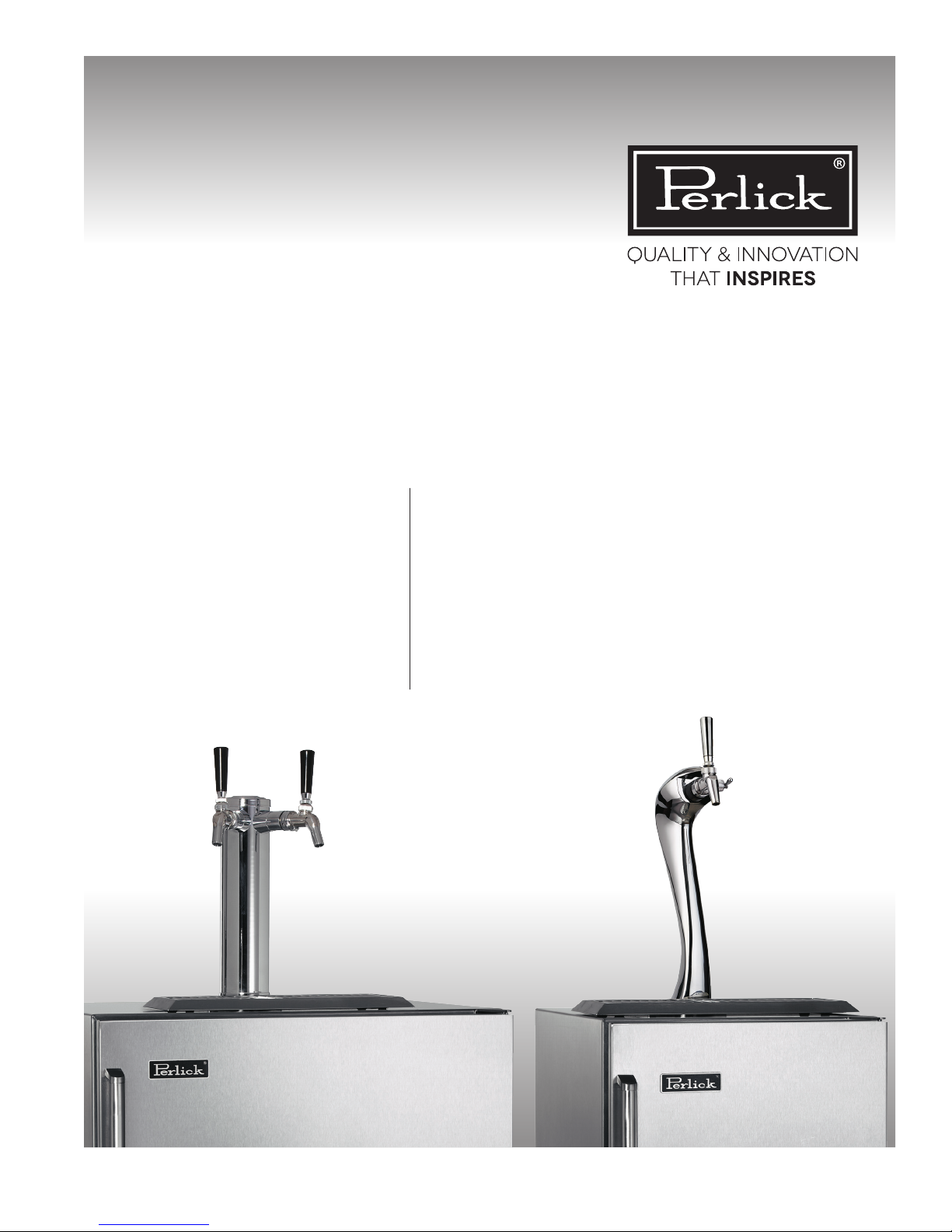
Installation Manual
for Beer Dispensing Equipment
HP15TS/TO
HP24TS/TO
HC24TB/TO
HP15TS-3-**A
HP24TS-3-***A
15” SIGNATURE SERIES
24” SIGNATURE SERIES
24” C-SERIES
15” SIGNATURE SERIES ADARA
24” SIGNATURE SERIES ADARA
Form No. Z2349
Rev. 06/17/2015
Page 2
PERLICK RESIDENTIAL INSTALLATION MANUAL FOR BEER DISPENSING EQUIPMENT
DANGER
WARNING
DANGER
WARNING
CONGRATULATIONS
Congratulations on your purchase of a Perlick high
quality residential Beer Dispenser. Perlick has proudly
manufactured beer dispensing systems for over 50 years
for bars, restaurants, stadiums, arenas and large venues
around the world. That same technology is used in each
and every residential beer dispenser we produce, assuring
you’ll pour fresh, cold beer as the brewery intended it to
be enjoyed.
All Perlick products are built with commercial grade
stainless steel, providing you with the beauty and durability
for a lifetime of use. This installation guide will show you
how to properly install the dispensing equipment on your
Perlick Beer Dispenser.
We dedicate considerable time to ensure that our products
provide the highest level of customer satisfaction. If,
however, service is required, call Perlick at 800.558.5592.
For your own protection, never return merchandise for
credit without our approval.
IMPORTANT!
The installation of the actual beer
dispenser cabinet should happen prior
to installing the dispensing equipment.
Refer to the Installation Manual that
accompanied the Beer Dispenser for step-
by-step installation of the cabinet.
PLEASE NOTE
The following instructions are for both the
Draft Arm (standard tower) and the Adara
Signature Beer Tower. Some photos and
drawings may only show the Draft Arm, but
the instructions will also apply to the Adara
Signature Beer Tower unless noted.
We thank you again for selecting a high quality Perlick Beer
Dispenser. Cheers!
Keep CO2 cylinder away from
heat. Rupture disc vents at 122°F
maximum.
Do not drop or throw regulator or
CO2 cylinder.
Allow only properly trained and
experienced personnel to handle
high pressure gas.
Do not apply oil to the regulator!
C
2
US
perlick.com
Page 3
PERLICK RESIDENTIAL INSTALLATION MANUAL FOR BEER DISPENSING EQUIPMENT
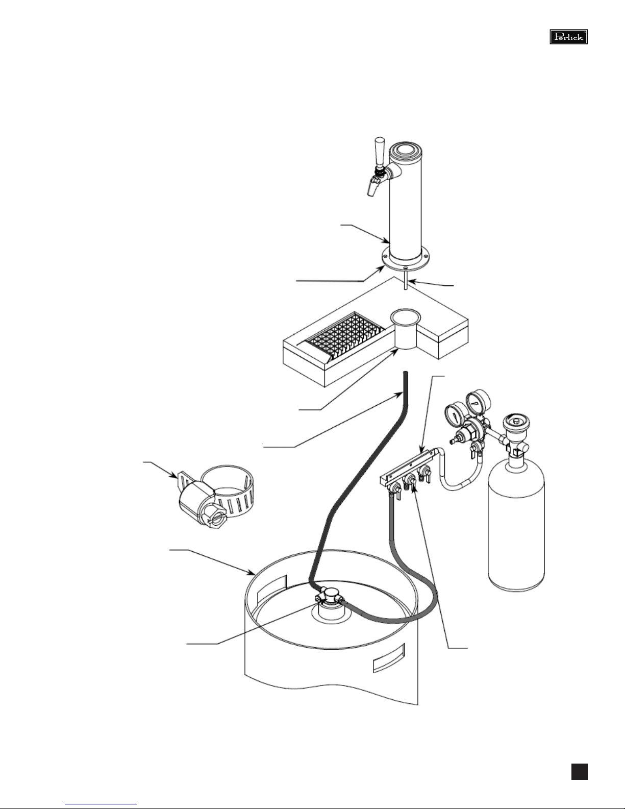
INSTALLATION OF DISPENSING EQUIPMENT
Open the tapping kit box and become familiar with
its components. The instructions on pages 4 through
8 will demonstrate how to properly install the tapping
equipment on your new Perlick Beer Dispenser.
Dispensing Head
All hose connections
use worm-drive
hose clamps (view
enlarged to verify)
Keg
Apply silicone to
bottom ange
Flange Sleeve
Beer Connection
Faucet Lead
Air Distributor
Keg Coupler
NOTE: Image does not accurately reect positions of the
dierent elements within the unit. Positions and hose lengths
shown are to clearly illustrate proper connection methods
only.
Distributor is only on
multiple keg units,
each keg is connected
to a valve on the air
distributor. Single keg
is connected directly to
the regulator.
perlick.com
3
Page 4
PERLICK RESIDENTIAL INSTALLATION MANUAL FOR BEER DISPENSING EQUIPMENT
INSTALLATION OF DISPENSING EQUIPMENT
Open the tapping kit box and become familiar with
its components. If the dispensing head is going to be
mounted on a counter top directly above the refrigerated
cabinet, have the counter top pre-drilled using the
supplied template on page 11. Make sure that the access
hole in the refrigerated cabinet is in line with the counter
top holes. Remove any obstructions from the access hole
of the refrigerator.
Follow instructions on pages 4 through 9 to properly install
the tapping equipment on your perlick unit, or watch our
Beer Dispenser Tapping Installation video. Information on
how to access this video can be found to the right.
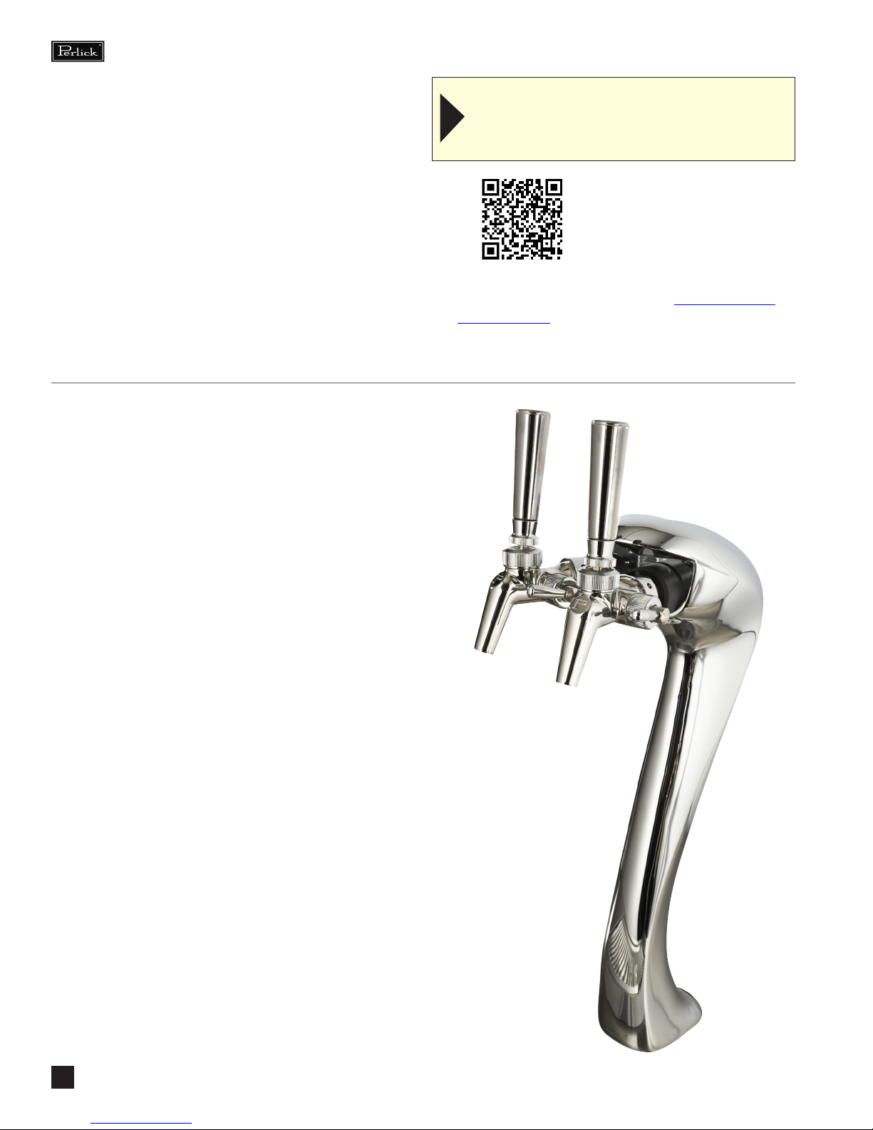
IF YOU ARE INSTALLING A DRAFT ARM - SKIP TO
PAGE 5. THE FOLLOWING INSTRUCTIONS ARE
ADDITIONAL PREPARATION STEPS FOR THE ADARA
DISPENSING HEAD ONLY
NOTE: Wash tapping devices thoroughly. Flush
beer and faucet lines, as well as the tapping device
(keg coupler) with fresh water.
Scan the QR code with your
mobile device to watch the
video instantly.
Use the following web link to view the video
through your browser window: http://youtu.be/
NCKP6x2zZmo
1. Mark the air tube for correct length dependent upon
your installation scenario. If installing directly on top
of the refrigerated cabinet, make a mark 5 inches from
the bottom of the tower. If installing directly on top of
a countertop, aadd the delth of the countertop to the
original 5 inches and mark at that new dimension.
2. Remove air “T” from end of air tube by loosening
fastener holding the two halves together. Remove the
air tube from the tower being careful not to damage
the product tube.
3. Cut air tube at mark made in step 1. Re-install air tube
into tower and re-install “T” on the end of the air tube
so “T” faces the rear of the tower.
4. Cut product tube 3 inches below the “T” and install
included barbed union into product tube and clamp
using worm drive clamp.
perlick.com
4
Page 5

PERLICK RESIDENTIAL INSTALLATION MANUAL FOR BEER DISPENSING EQUIPMENT
1.
Locate the dispensing head , black beer line(s), and
hose clamp(s). Slide one end of each beer line onto the
stainless steel tubes which protrude out the bottom of
the dispensing head and clamp tight.
2.
Remove transit tape with a utility knife around the hole
in the top of the unit from both inside and outside of
the cabinet. Gently punch out foam w/screwdriver and
remove. Insert the beer line(s) through the hole in the
counter top. Move head aside and bead silicone around
perimeter of hole, and then position the head back
in place. Fasten using the 4 chrome screws included
with the dispensing head. Wipe o excess silicone to
complete the seal.
3.
Use the 3/8” -thick foam pad included in the tapping kit
and roll into a cylinder. From inside the cabinet, insert
the foam tube up through the hole in the counter top
until it is rmly against the insulation in the dispensing
head. Mark, then cut away any excess foam.
NOTE: If using an Adara tower, foam needs to be installed
so that it is pressed up against the bottom mounting ange
of the tower.
perlick.com
5
Page 6

PERLICK RESIDENTIAL INSTALLATION MANUAL FOR BEER DISPENSING EQUIPMENT
4.
Install the Air Scoop Kit. Start by removing the upper set
of screws located above the fan on the back wall of the
cabinet.
5.
Assemble components from the kit as follows – Insert
black snap bushing into air scoop mounting bracket,
then insert one end of the air snorkel through the snap
bushing. A zip tie can be inserted behind the mounting
bracket to keep the tube in place.
NOTE: For Adara Towers, the air snorkel consists of a 3 inch
piece of black tubing and a 3 inch piece of clear tubing that
slides over each other and then is clamped using included
worm drive clamp. The black tube is inserted per the above
instructions and secured with the included zip tie. The clear
tube is installed over the air “T” from the dispensing head
and secured with the included worm drive clamp.
6.
Insert end of the snorkel up into the tower and screw
air scoop mounting bracket into vacated holes above
the fan.
perlick.com
6
Page 7

PERLICK RESIDENTIAL INSTALLATION MANUAL FOR BEER DISPENSING EQUIPMENT
7.
If installing a two faucet system, a CO2 manifold will
need to be installed. Locate the red CO2 lines, CO2
manifold and a #10 x 1/2” sheet metal screw. Slide
one end of each hose onto the barbed ttings on the
manifold and clamp. On the left rear side wall of the
beer compartment there is a double row of screws
which run vertically. Remove one of the two top screws
and discard. Insert the sheet metal screw through the
manifold and into the hole vacated previously.
8.
On a single beer system, locate the red CO2 hose.
Slide one end onto the barbed tting of the regulator
assembly and clamp. On systems with two beers, locate
the CO2 line that comes o the backside of the manifold
assembly. Slide the hose onto the barbed tting of the
regulator assembly and clamp. For detailed information
on connecting the regulator to the CO2 cylinder, see
page 10.
9.
Locate the low prole keg coupler(s). Slide one of the
red CO2 lines onto the larger barbed tting of coupler
and clamp. Locate one of the black beer lines and slide
onto the smaller barbed tting of the coupler and clamp.
Repeat for additional couplers.
perlick.com
7
Page 8

PERLICK RESIDENTIAL INSTALLATION MANUAL FOR BEER DISPENSING EQUIPMENT
10.
On the right rear sidewall there is a double column of
screws. Remove the left screw. Locate the safety chain
and a #10 x 1/2” sheet metal screw from the parts bag.
Insert the screw through the closed end link of the chain
and tighten in the vacant screw hole. The chain can now
be used to secure the tank with “S” hook, preventing
damage to the regulator.
11.
CO2 tanks are shipped empty and must be lled
prior to use. Turn the adjusting knob on the regulator
counter-clockwise until the secondary gauge (top)
reads zero. Make sure that the valve at the bottom of
the regulator where the red hose is connected is in
the o position as shown. Watching the secondary
pressure gauge, turn the regulator adjusting
knob clockwise until the pressure is at 15 psig.
Adjustments can later be made based on ow rates.
IMPORTANT: All pressure adjustments MUST be made
when the shut-o valve is in the OFF position!
12.
Locate the beer faucet(s) and install onto the dispensing
head shanks. Tighten with supplied spanner wrench.
Install black handle(s) onto faucet(s).
perlick.com
8
Page 9

PERLICK RESIDENTIAL INSTALLATION MANUAL FOR BEER DISPENSING EQUIPMENT
13.
Before tapping, make sure the beer faucet is closed. To
tap a keg, insert the coupler into the neck of the barrel.
Turn the coupler clockwise until it stops (about an 1/8
turn), then push down on the top of the coupler and
again turn clockwise until it stops. Your barrel is now
tapped. Open the CO2 valve on the regulator as well as
the valve on the manifold if used.
perlick.com
9
Page 10

PERLICK RESIDENTIAL INSTALLATION MANUAL FOR BEER DISPENSING EQUIPMENT
CONNECTING THE REGULATOR TO THE CO2 CYLINDER
1. Remove the blue plug from the regulator tting, but do
not remove the carbonic washer.
2. Screw regulator onto gas cylinder valve. Tighten with
wrench until vertically straight. Be sure that the shut-o
valve on the regulator is in the OFF (horizontal) position.
3. Place screw clamp over the end of red line and push onto
regulator tail piece. Tighten clamp with a screwdriver.
4. Turn regulator adjusting screw counterclockwise until
it turns freely.
5. Turn hand valve counter-clockwise on the CO2 cylinder
to the fully open position.
6. Turn regulator adjusting screw clockwise until desired
pressure is reached (approximately 12-15 lbs.) Tighten
stop nut on adjusting screw.
7. Open shut-out valve on bottom of regulator.
8. Dilute a small amount of liquid dishwashing soap and
rub the soapy mixture around connections. If bubbles
appear, tighten connection.
perlick.com
10
Page 11

PERLICK RESIDENTIAL INSTALLATION MANUAL FOR BEER DISPENSING EQUIPMENT
MOUNTING HOLE TEMPLATE FOR DRAFT ARMS
AND ADARA SIGNATURE TOWERS
NOTE: The hole placement for the Draft Arm and Adara
towers are the same even though the decorative anges
are dierent shapes.
perlick.com
11
Page 12

Use and Care Guides, Specication Sheets, Wood Overlay Templates for Doors, Drawers and
Grilles, and Corresponding Compliance and Energy Guides are available for download at
www.perlick.com/residential-products/service-support.
Contact Perlick Customer or Technical Service at
800.558.5592.
Customer Service and Technical Service are available business days
Monday through Friday from 8 a.m. to 4:30 p.m. CST.
8300 W. Good Hope Road, Milwaukee, WI 53223 • 800.558.5592 • info@perlick.com • www.perlick.com
Form No. Z2349
Rev. 06/17/2015
 Loading...