

Page 1
HOW TO ASSEMBLE AND INSTALLATION
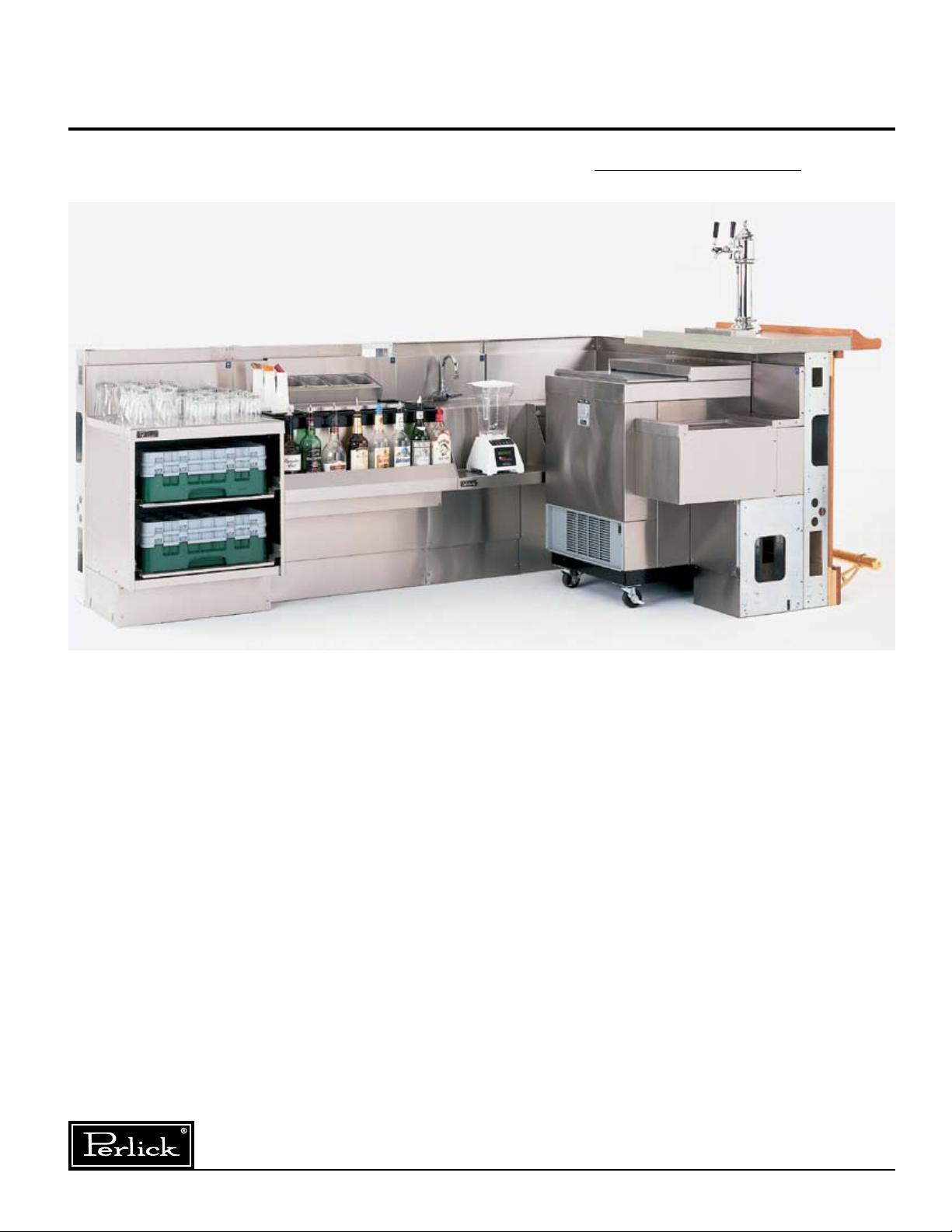
THE PERLICK MODULAR BAR DIE SYSTEM
MODEL NOS.
MBS
IMPORTANT INSTALLATION INFORMATION
The Perlick Modular Bar Die System makes building
a bar quick and easy. The bar die arrives on the job
site in sections up to eight feet long with stainless
steel underbar equipment already installed, saving
time and labor costs.
FLOOR PREPARATION
We suggest the bar die be installed on an unfinished
floor. Tile can then belaid, abutted to the bar die, to form
a watertight seal.
These illustrated, easy to follow instructions help to
ensure a professional, trouble-free installation.
8300 West Good Hope Road • Milwaukee, WI 53223 • Phone 414-353-7060 • Fax 414-353-7069
Toll Free 800-558-5592 • E-Mail: Perlick@Perlick.com • www.Perlick.com
Table of Contents
General Information ............................................... 2
Utility Specs ..........................................................2
Floor Sink Location ...............................................3
Uncrating ............................................................... 4
Placing ...................................................................4
Joining ................................................................... 4
Leveling ................................................................. 5
Attaching Bar Die to the Floor ..............................5
Installing Beer Lines .............................................. 5
Installing Utility Lines ............................................ 6
Sealing the Bar to the Floor ..................................6
Front Finishing Panels ........................................... 7
Bar Top ..................................................................8
Soda Guns ............................................................ 8
Form No. Z2162
Rev. 06.12.10
Page 2
General Information
Tools and Equipment Required
Phillips screwdriver Level
Power drill with various bits Marking pencil
Clamps (optional) Tape measure
Chalk Line
Fasteners
#10-16 x 3⁄4" Phillips Round Head
Thread Cutting Screw
Use to assemble Modular Bar
sections.
Actual Size
Not Shown
#10-16 x 1⁄2" Phillips Pan Head
Use to attach front panel clips;
secure to bar top.
#7055-45 Connector Kit used to
assemble workboard equipment
sections.
Arrival at the Job Site
Remove crate top, sides, ends and exposed lag bolts
holding structure to the crate skid. Note: Whenever
possible, the underbar equipment has been attached
to the bar structure. Free-standing equipment such as
bottle coolers, frosters, etc, are to be set into the open
sections which have been programmed into the bar
structure.
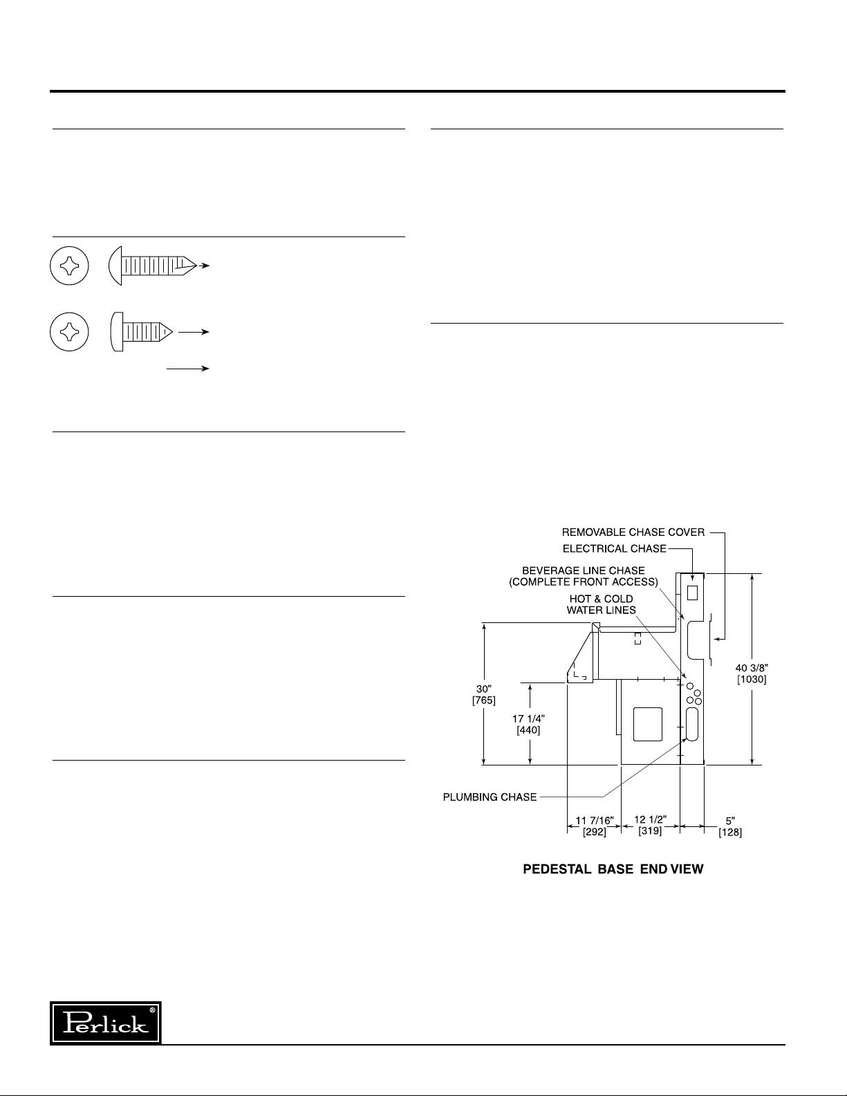
Utility Specifications
A 5" open zone is furnished behind the equipment
to provide room for trunk lines, soda lines, plumbing,
electrical, etc. to travel vertically or horizontally within
the bar structure.
Connections can be made from the front of the bar
with panels removed.
Plumbing and Electrical
(Installed According to Local Codes)
All water service and waste connections can be
made from the front of the bar (decorative front panel
removed). Local codes dictate installation (by others).
All electrical requirements such as receptacle to
blenders, washers, coolers, soda guns, lights, etc. (by
others).
Plug-in flourescent lighting is available in conjunction
with 8020-51 backsplash electrical outlets.
General Specifications
Structure: Configured to the exact size and shape
of underbar equipment, freestanding cabinets and
openings, as specified.
Chase: Interior chase runs the entire length of
structure to include corners.
Millwork
: By others.
Mechanical Specifications
Utility Lines: Dedicated chase locations for hot/cold
water supply lines, beverage line conduits, and electrical conduit (behind the underbar equipment.) See
drawing. This chase is accessible from the floor and
runs the entire length of the bar.
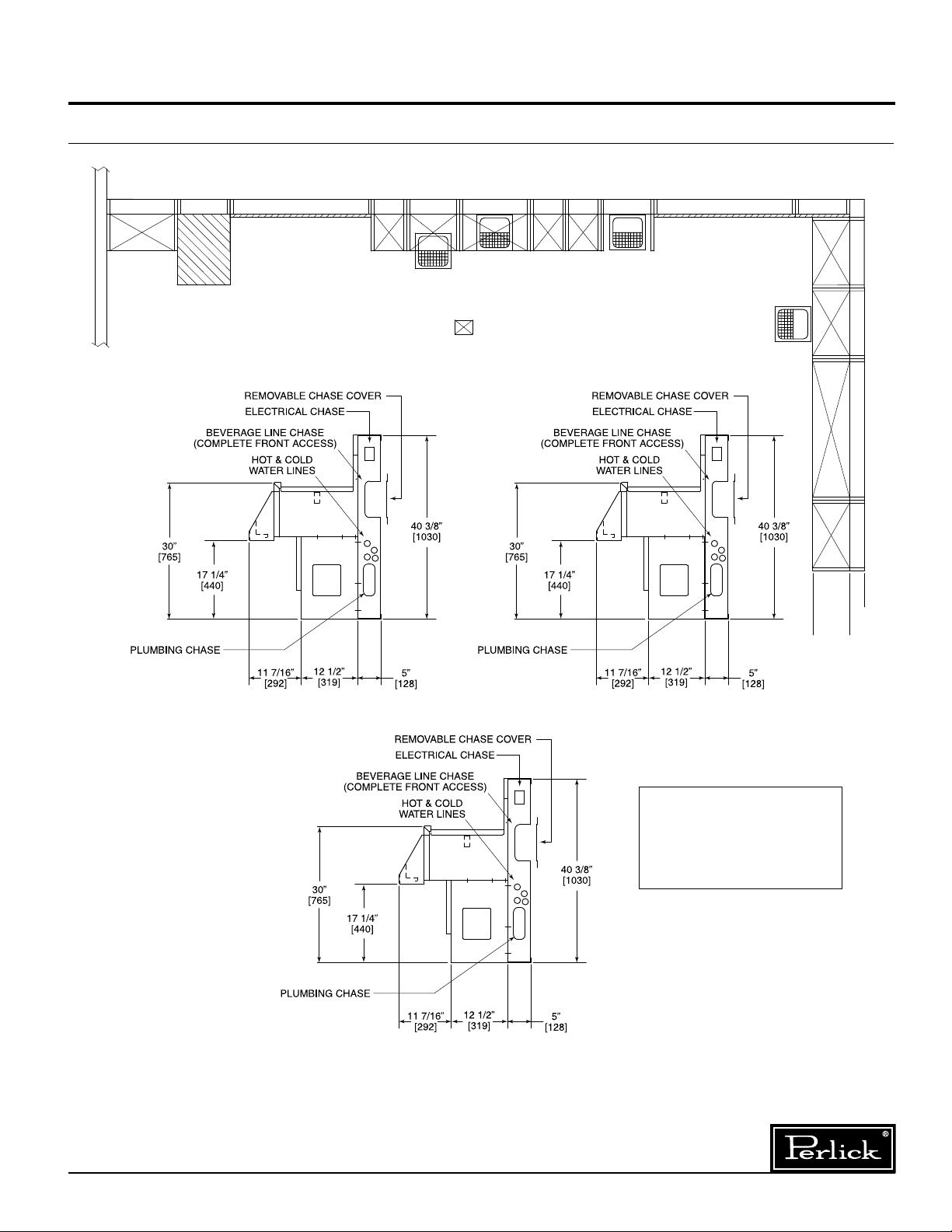
Floor Drains
workboard equipment. The number of floor drains will
vary depending on the bar layout and local codes.
: Locate floor drains directly below
Form No. Z22162
Rev. 06.12.10
Perlick is committed to continuous improvement. Therefore, we reserve the right to change specifications without prior notice.
2
Page 3
Option 1
Option 2
Option 4
Option 2
Available Soon
Options 2 & 3
Option 4
Option 1
Locating Floor Sinks
Choose yo u r o p ti o n
depending upon local
codes.
“FOOT PRINT”
(LIMITED ACCESS BELOW)
5”
12 1/2”
DENOTES OPEN AREA
FOR UTILITY STUB-UPS
General Information
Before You Begin: Floor Sink Location
Perlick is committed to continuous improvement. Therefore, we reserve the right to change specifications without prior notice.
3
Form No. Z22162
Rev. 06.12.10
Page 4

General Information
Uncrating
Uncrate and remove skids from underneath
Modular Bar.
Placing
Joining
a) Screws are installed from the outside of
the bar structure from right to left.
b) Loosely attach sections through holes in
vertical studs. Do not tighten completely
until bar is completely leveled.
Use #10-16 x
provided. (Typ. 6 places).
3
⁄4" thread cutting s.m.s.
Move sections to desired location, over previouslyplaced beverage line conduits, plumbing and electrical rough-in stub ups.
Form No. Z22162
Rev. 06.12.10
Perlick is committed to continuous improvement. Therefore, we reserve the right to change specifications without prior notice.
4
Page 5

General Information
Leveling
a) Use wood or steel shims to level bar sections.
Note: The bar structure must be level so that the
equipment fits properly.
b) Any gaps created from leveling will be
hidden when the finish flooring is installed.
c) Join stainless steel equipment modules
together (use 7055-45 or 7055-55
Connector Kit).
d) Seal Modular Bar sections using NSF approved caulk.
Attaching Structure to the Floor
a) Temporarily insert freestanding equipment to
ensure proper fit.
b) Bar die can be attached to the floor using holes
in the bottom plate.
c) Several different methods can be used to
fasten bar to the floor. The installing contractor
will select the best method for your individual
installation.
Installing Beer Lines
a) Remove chase cover plate prior to installation.
b) An open utility chase is provided for easy beer
trunk housing installation.
c) Replace chase plate when installation is
complete.
With chase plate removed.
Perlick is committed to continuous improvement. Therefore, we reserve the right to change specifications without prior notice.
5
With chase plate in place.
Form No. Z22162
Rev. 06.12.10
Page 6

General Information
Installing Utility Lines
Ample space is provided for electrical and plumbing lines.
See Utility Specifications on page 2.
Sealing Structure to the Floor
a) Loosen lower finish panel screws until lower
panel drops to the floor (1" adjustment).
b) Tighten finish panel screws.
c) Tile floor.
d) For sanitary purposes, the bar can then be
sealed to the floor using your choice of methods.
Form No. Z22162
Rev. 06.12.10
Perlick is committed to continuous improvement. Therefore, we reserve the right to change specifications without prior notice.
6
Page 7

General Information
Front Panels (Shown for Reference Only)
Front Panels
Removable customer-side front panels are
meant to provide access for installation and
future servicing.
Method A
In this method panels hang on the front lower
structure rail.
a) Panel clips (not included) are attached to the
inside of the bar front panel.
b) Place clip over lower finish panel.
c) Use screws to attach panel to the
upper part of the structure.
Method B
In this method panels slide into a channel created
by two pieces of wood.
a) No screws or fasteners
required.
b) Panels lift up and swing
out for service.
End Panels
End panels to conceal the structure at gate
openings or bar end, etc. are not supplied by
Perlick. They should be fabricated by the
millworker.
Perlick is committed to continuous improvement. Therefore, we reserve the right to change specifications without prior notice.
7
Form No. Z22162
Rev. 06.12.10
Page 8

General Information
Bar Top and Bar Rail by Others
(Shown for Reference Only)
The underside of the bar top should have a flat
single plane.
a) After all other steps have been completed, place
the assembled bar top in position.
Note: If bar layout includes a Model 8000 ice
cream unit, place into module before
installing top.
b) Fasten top to bar structure using #10 x 1/2" long
round head screws.
Soda Guns
Soda gun locations should be predetermined so the
factory can provide an opening for soda hoses.
a) Wunderbar brand soda hose manifolds can be
attached to the underside of the bar top
in front of filler strip, taking into consideration any
underbar lighting which may be present.
b) Six inch stainless steel Manifold Housing for
Concealing Soda Manifold. Installs on TS6CO.
Accessory Part #7055-66SG.
Form No. Z22162
Rev. 06.12.10
Perlick is committed to continuous improvement. Therefore, we reserve the right to change specifications without prior notice.
8
 Loading...